EP0875777A2 - Kabelmuffe für Lichtwellenleiterkabel - Google Patents
Kabelmuffe für Lichtwellenleiterkabel Download PDFInfo
- Publication number
- EP0875777A2 EP0875777A2 EP98105968A EP98105968A EP0875777A2 EP 0875777 A2 EP0875777 A2 EP 0875777A2 EP 98105968 A EP98105968 A EP 98105968A EP 98105968 A EP98105968 A EP 98105968A EP 0875777 A2 EP0875777 A2 EP 0875777A2
- Authority
- EP
- European Patent Office
- Prior art keywords
- cable sleeve
- cable
- groove
- sleeve according
- flat
- Prior art date
- Legal status (The legal status is an assumption and is not a legal conclusion. Google has not performed a legal analysis and makes no representation as to the accuracy of the status listed.)
- Granted
Links
Images

Classifications
-
- G—PHYSICS
- G02—OPTICS
- G02B—OPTICAL ELEMENTS, SYSTEMS OR APPARATUS
- G02B6/00—Light guides; Structural details of arrangements comprising light guides and other optical elements, e.g. couplings
- G02B6/46—Processes or apparatus adapted for installing or repairing optical fibres or optical cables
- G02B6/50—Underground or underwater installation; Installation through tubing, conduits or ducts
- G02B6/504—Installation in solid material, e.g. underground
-
- G—PHYSICS
- G02—OPTICS
- G02B—OPTICAL ELEMENTS, SYSTEMS OR APPARATUS
- G02B6/00—Light guides; Structural details of arrangements comprising light guides and other optical elements, e.g. couplings
- G02B6/44—Mechanical structures for providing tensile strength and external protection for fibres, e.g. optical transmission cables
- G02B6/4439—Auxiliary devices
- G02B6/444—Systems or boxes with surplus lengths
- G02B6/4441—Boxes
- G02B6/4446—Cable boxes, e.g. splicing boxes with two or more multi fibre cables
- G02B6/44465—Seals
-
- G—PHYSICS
- G02—OPTICS
- G02B—OPTICAL ELEMENTS, SYSTEMS OR APPARATUS
- G02B6/00—Light guides; Structural details of arrangements comprising light guides and other optical elements, e.g. couplings
- G02B6/46—Processes or apparatus adapted for installing or repairing optical fibres or optical cables
- G02B6/50—Underground or underwater installation; Installation through tubing, conduits or ducts
- G02B6/501—Underground or underwater installation; Installation through tubing, conduits or ducts underground installation of connection boxes
Definitions
- the invention relates to a cable sleeve for fiber optic cables.
- connection, branch or Distribution sleeve for fiber optic cables known for the inclusion, splicing and splitting of optical fibers is suitable, with the possibility of storing excess lengths of optical fibers with splice cassettes.
- This Arrangements are made, for example, in cylindrical cable gland housings housed that from a socket pipe and front Sealing bodies exist or as hood sleeves are trained.
- Such sleeve housings are suitable, however not for use in fiber optic cable systems that in solid surfaces such as a road surface are misplaced because the effort involved in installing them is too great. So-called underfloor containers have so far been used here.
- the object of the invention is now to create a cable sleeve, which are introduced at a relatively shallow depth into the fixed installation foundation can be and in which the requirements for the Splicing of optical fibers and the storage of excess optical fibers, for branching and dividing be fulfilled.
- the task is done with a cable sleeve for fiber optic cables solved in that the cable sleeve is designed as a flat sleeve that a circular Groove in the flat sleeve is arranged that introductions for optical waveguides open tangentially into the circular groove, that cable clamps are arranged in the entries are and that a cover with a seal to cover the groove is arranged.
- An advantage results when using the inventive Cable sleeve in that it is due to the flat design at very shallow depths, especially in the shallow ones Laying depth of the fiber optic cables routed in a fixed manner like microcables used in a simple way can be.
- These micro cable systems run in installation grooves preferably at a depth of about 30 mm, so that the entries in this flat cable sleeve at the same depth can.
- the cable sleeve according to the invention can be used as a washer or be designed as a ring in the circular or Grooves are formed. These grooves are connected tangential entries, so that the optical fiber after Removal of the cable sheath or the tube in the same Level can be continued.
- the Cable sleeve Preferably to the Cable sleeve four entries provided; two each lie in a tangent line. However, there are also additional ones Entries possible with appropriate connection pieces then appropriate connection piece provided or can be attached later.
- the cable sleeve according to the invention can be designed as a disc as well as a ring be, the latter embodiment being particularly advantageous is when manufacturing the routing grooves for the microcables ring grooves for later installation to be used milled cable sleeves of the type according to the invention will.
- Figure 1 shows an embodiment of the cable sleeve according to the invention in the form of a flat sleeve, wherein an annular design is selected here.
- this flat sleeve could also be designed as a disc in which the circular grooves are formed.
- the grooves 3 run in the ring 2, to which tangential cable entries 4 are attached.
- two entries 4 are arranged in a tangent line, so that, for example, a straight-line continuation without splicing is also possible.
- the inserted cable sheaths or, in the case of microcables the tubes 14 are intercepted, preferably in a clamping groove which is or will be adapted accordingly to the diameter of the inserted cable.
- the tube 14 is removed in the required length, for example with a special removal tool with which the tube is milled along the surface lines.
- uncut optical fibers 9 are circulated in the groove 3 through the opposite insertion 4 is carried out again in the continuing micro cable, while a part of the optical fibers is spliced with the optical fibers of the branch cable 11, for example the spliced optical fiber 12 is connected via the splice 13 to the optical fiber 10 of the branch cable 11 and to this via the incision (breakout ) 6.
- the inlets 4 are covered with separate clamping covers 7, by means of which the requirements of the clamping and the sealing are produced, however, the clamping areas can also be closed off by a cover covering the entire sleeve rhin indicated that a connecting S-shaped diagonal groove 15 can be provided within the ring 2, in which optical fibers can also be performed.
- This has the advantage that a reversal of direction can take place through this guide in the S-shaped diagonal, so that optical fibers, for example, can also be routed to the inlet 4 on the top right without problems.
- This configuration can also be designed as a disc, then the grooves in the same way in the disc body run.
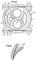
- FIG. 2 shows a flat sleeve 16 as an exemplary embodiment shown, in which the circular groove is also in a ring runs, but within the ring an 8-shaped Diagonal groove 18 is included.
- Introductions 19 are provided in their clamping areas the cable sheaths of fiber optic cables or the pipes can be clamped by micro cables 22 intercepted. In holes 20 grip corresponding clamping elements such as screws or the like.
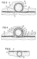
- the microcable 34 is then removed from the annular groove 30 removed and from its cable jacket or its tube exempted.
- annular flat sleeve is inserted according to the invention and the exposed optical fibers in the circular Groove of the flat sleeve inserted after appropriate splice, as already described above.
- FIG. 4 shows the final state of that already described in FIG. 3 Sleeve insertion. So are in the groove 34 Flat sleeve already the optical fiber 35 and the splice 33 and 37 inserted. There is also another one here Variant shown, in addition to the molded entries the flat sleeve is another introduction for a cable 36 was arranged. For this there is an opening to the groove 34 inserted in the flat socket or already provided, in which a connecting piece 38 has been used. In the The same type can also be grounding bushings or other Introductions can be provided for a variety of purposes.
- Figure 5 illustrates that a flat sleeve 39 of a micro cable system 34 according to the invention not only as in the figures 3 and 4 horizontally but also vertically in the fixed Installation reason can be introduced. This is an advantage if there is little space on the side or if the flat sleeve is protected against particularly high loads shall be.
- Figure 6 finally shows a spiral protective tube as rodent protection for the ring-shaped flat sleeves of the connection, which are wrapped around the flat sleeve.
- the cable sleeves according to the invention can also be used in aerial cable systems can be used advantageously, for example two entries lying in a tangent line for attachment to a suspension cable or an earth rope High-voltage system can be used as a clamping device can. So for longer lengths or in the event of a defect one lashed fiber optic cable a splice in be made in a simple and uncomplicated manner, especially since it is very easy to assemble in the versions according to the invention Sleeves are concerned. There is also a mast arrangement made possible in a simple manner by the clamping devices.
- opening of the cover or covers are provided, for example using eyelets or approaches for mechanical opening.
- a pneumatic opening can also take place if e.g. via a pressure supply inside the flat sleeve an overpressure is generated so that the cover or Covers are lifted off.
- the flat sleeves according to the invention consist of corrosion-resistant Material, preferably made of metal, cast metal, plastic or glass fiber reinforced plastic.
- the flat sleeve according to the invention is used as a connection and Branch sleeve used and there can be at least 200 in it Fibers or optical fibers cut and / or uncut be filed. In the same time as strain relief trained entries can also be earth connections be made.
- the well-known Splice types such as crimp splicing, shrink tubing splicing and preferably Techni-Tubes can protect the splices can also be used.
- the preferred dimensions, but not mandatory, when laying in connection with micro cable systems are as follows: - Inner diameter of a circular installation groove in the installation base 150-300 mm - Groove width of a laying groove in the laying reason 30 mm - Groove depth of one installation groove in the installation reason 30 mm - Length of the recess in the routing groove for receiving the cable sleeve entries 250 mm - Groove width of the flat sleeve 20 to 25 mm - Groove depth of the flat sleeve approx. 10 mm - Length of the entry area of two entries 240 mm
- the grooves of the flat sleeve according to the invention also with suitable, in the cable fittings technology itself known fillers can be filled, the corresponding Filling openings are pressed.
Landscapes
- Physics & Mathematics (AREA)
- General Physics & Mathematics (AREA)
- Optics & Photonics (AREA)
- Light Guides In General And Applications Therefor (AREA)
- Mechanical Coupling Of Light Guides (AREA)
Abstract
Description
- Figur 1
- zeigt die Ausbildung einer ringförmigen Kabelmuffe.
- Figur 2
- zeigt die Ausbildung einer ringförmigen Kabelmuffe mit einer zusätzlichen 8-förmigen Diagonalnut.
- Figur 3
- zeigt die Ausbildung einer ringförmigen Nut für die Aufnahme einer Kabelmuffe beim Verlegevorgang.
- Figur 4
- zeigt eine Kabelmuffe in waagerechter Anordnung im Verlegegrund mit der Ausbildung einer zusätzlichen Einführung.
- Figur 5
- zeigt den senkrechten Einsatz einer Kabelmuffe.
- Figur 6
- zeigt einen nagetiersicheren Schutz für eine ringförmige Kabelmuffe.

| - innerer Durchmesser einer kreisförmigen Verlegenut im Verlegegrund | 150 - 300 mm |
| - Nutbreite einer Verlegenut im Verlegegrund | 30 mm |
| - Nuttiefe einer Verlegenut im Verlegegrund | 30 mm |
| - Länge der Aussparung der Verlegenut für die Aufnahme der Einführungen der Kabelmuffe | 250 mm |
| - Nutbreite der Flachmuffe | 20 bis 25 mm |
| - Nuttiefe der Flachmuffe | ca. 10 mm |
| - Länge des Einführungsbereiches von zwei Einführungen | 240 mm |
Claims (26)
- Kabelmuffe für Lichtwellenleiterkabel,
dadurch gekennzeichnet,
daß die Kabelmuffe als Flachmuffe ausgebildet ist, daß eine kreisförmige Nut in der Flachmuffe angeordnet ist, daß Einführungen für Lichtwellenleiterkabel tangential in die kreisförmige Nut einmünden, daß Kabelabfangungen in den Einführungen angeordnet sind und daß ein Deckel mit Dichtung zur Abdeckung der Nut angeordnet ist. - Kabelmuffe nach Anspruch 1,
dadurch gekennzeichnet,
daß die Flachmuffe als kreisrunde Scheibe ausgebildet ist, in der die Nut verläuft. - Kabelmuffe nach Anspruch 1,
dadurch gekennzeichnet,
daß die Flachmuffe als Ring ausgebildet ist, in dem die Nut verläuft. - Flachmuffe nach einem der vorhergehenden Ansprüche,
dadurch gekennzeichnet,
daß der Radius der kreisförmigen Nut mindestens dem minimal zulässigen Biegeradius der Lichtwellenleiter entspricht, aber vorzugsweise 150 bis 300 mm beträgt. - Kabelmuffe nach einem der vorhergehenden Ansprüche,
dadurch gekennzeichnet,
daß die Nuttiefe vorzugsweise 10 mm beträgt. - Kabelmuffe nach einem der vorhergehenden Ansprüche,
dadurch gekennzeichnet,
daß die Nutbreite der Flachmuffe vorzugsweise 20 bis 25 mm beträgt. - Kabelmuffe nach einem der vorhergehenden Ansprüche,
dadurch gekennzeichnet,
daß die Kabelabfangungen in den Einführungen als Klemmnut für den Kabelmantel des einzuführenden Lichtwellenleiterkabels, vorzugsweise für das Rohr eines Mikrokabels, ausgebildet ist. - Kabelmuffe nach einem der vorhergehenden Ansprüche,
dadurch gekennzeichnet,
daß eine S-förmige Diagonalnut im Kreis der Nut zur Richtungsumkehr der Lichtwellenleiterführung angeordnet ist. - Kabelmuffe nach einem der Ansprüche 1 bis 7,
dadurch gekennzeichnet,
daß eine 8-förmige Diagonalnut im Kreis der Nut angeordnet ist. - Kabelmuffe nach einem der vorhergehenden Ansprüche,
dadurch gekennzeichnet,
daß Lichtwellenleiterspleiße innerhalb der Nut abgelegt sind. - Kabelmuffe nach einem der vorhergehenden Ansprüche,
dadurch gekennzeichnet,
daß die Nut über eine Füllöffnung mit Füllmasse auffüllbar ist. - Kabelmuffe nach einem der vorhergehenden Ansprüche,
dadurch gekennzeichnet,
daß vier Einführungen tangential über Einmündungen an der kreisförmigen Nut angeordnet sind, wobei vorzugsweise je zwei Einführungen in einer Tangentenlinie gegeneinander gerichtet angeordnet sind. - Kabelmuffe nach einem der vorhergehenden Ansprüche,
dadurch gekennzeichnet,
daß die Muffe in einer Ringbohrung oder einer zylindrischen Bohrung eines festen Verlegegrundes, vorzugsweise einer Straßendecke, angeordnet ist. - Kabelmuffe nach einem der Ansprüche 1 bis 12,
dadurch gekennzeichnet,
daß die Kabelmuffe an einem Mast angeordnet ist. - Kabelmuffe nach einem der Ansprüche 1 bis 12,
dadurch gekennzeichnet,
daß die Kabelmuffe an einem durch zwei in einer Tangentenlinie liegenden Einführungen durchlaufend geführten Seil, vorzugsweise einem Tragseil oder einem Erdseil einer Hochspannungsanlage, angeklemmt ist. - Kabelmuffe nach einem der vorhergehenden Ansprüche,
dadurch gekennzeichnet,
daß in die Nut führende Anschlußstutzen für die Einführung weiterer Kabel angeordnet sind. - Kabelmuffe nach einem der vorhergehenden Ansprüche,
dadurch gekennzeichnet,
daß Erdungsdurchführungen angeordnet sind. - Kabelmuffe nach einem der vorhergehenden Ansprüche,
dadurch gekennzeichnet,
daß der Deckel Hilfsmittel, vorzugsweise Haken und/oder Ösen zum Öffnen aufweist. - Kabelmuffe nach einem der Ansprüche 1 bis 17,
dadurch gekennzeichnet,
daß der Deckel mit Hilfe eines über eine Druckzuführung hergestellten Überdruckes abnehmbar ist. - Kabelmuffe nach einem der vorhergehenden Ansprüche,
dadurch gekennzeichnet,
daß in den Nuten Überlängen von Lichtwellenleitern, ungeschnittene und/oder angeschnittene Lichtwellenleiter der eingeführten Lichtwellenleiterkabel eingelegt sind. - Kabelmuffe nach einem der vorhergehenden Ansprüche,
dadurch gekennzeichnet,
daß die Kabelmuffe aus korrosionsfestem Material, vorzugsweise aus Metall, Metallguß, Kunststoff oder glasfaserverstärktem Kunststoff gefertigt ist. - Kabelmuffe nach einem der vorhergehenden Ansprüche,
dadurch gekennzeichnet,
daß die Kabelmuffe mit Schutzmaterialien gegen Nagetier- oder Termitenbiß umgeben ist. - Kabelmuffe nach einem der vorhergehenden Ansprüche,
dadurch gekennzeichnet,
daß der Deckel den Bereich der kreisförmigen Nut und der S-förmigen oder 8-förmigen Nut sowie die Klemmbereiche der Einführungen überdeckt. - Kabelmuffe nach einem der Ansprüche 1 bis 22,
dadurch gekennzeichnet,
daß der Deckel den Bereich der kreisförmigen Nut und der S-förmigen oder 8-förmigen Nut überdeckt und daß die Klemmbereiche der Einführungen mit separaten Klemmdeckeln abgedeckt sind. - Kabelmuffe nach einem der vorhergehenden Ansprüche,
dadurch gekennzeichnet,
daß die Kabelmuffe waagerecht im Verlegegrund eingesetzt ist. - Kabelmuffe nach einem der Ansprüche 1 bis 24,
dadurch gekennzeichnet,
daß die Kabelmuffe senkrecht nach unten im Verlegegrund eingesetzt ist.
Applications Claiming Priority (2)
| Application Number | Priority Date | Filing Date | Title |
|---|---|---|---|
| DE19718477 | 1997-04-30 | ||
| DE19718477 | 1997-04-30 |
Publications (3)
| Publication Number | Publication Date |
|---|---|
| EP0875777A2 true EP0875777A2 (de) | 1998-11-04 |
| EP0875777A3 EP0875777A3 (de) | 1998-12-16 |
| EP0875777B1 EP0875777B1 (de) | 2003-01-02 |
Family
ID=7828352
Family Applications (1)
| Application Number | Title | Priority Date | Filing Date |
|---|---|---|---|
| EP98105968A Expired - Lifetime EP0875777B1 (de) | 1997-04-30 | 1998-04-01 | Kabelmuffe für Lichtwellenleiterkabel |
Country Status (3)
| Country | Link |
|---|---|
| US (1) | US6130982A (de) |
| EP (1) | EP0875777B1 (de) |
| DE (1) | DE59806781D1 (de) |
Cited By (3)
| Publication number | Priority date | Publication date | Assignee | Title |
|---|---|---|---|---|
| WO2003060585A1 (de) * | 2002-01-18 | 2003-07-24 | Ccs Technology, Inc. | Verfahren zum verlegen eines lichtwellenleiterkabels in einer gasleitung sowie kabelverlegeanordnung |
| EP2116881A1 (de) * | 2008-05-07 | 2009-11-11 | Nexans | Ablageeinheit zur Verteilung von Glasfasern |
| US8303384B2 (en) * | 2006-04-11 | 2012-11-06 | Airbus Deutschland Gmbh | Device for mixing fresh air and heating air and use of the device in a ventilation system of an aircraft |
Families Citing this family (10)
| Publication number | Priority date | Publication date | Assignee | Title |
|---|---|---|---|---|
| DE10003636A1 (de) * | 2000-01-28 | 2001-08-02 | Rxs Schrumpftech Garnituren | Muffeneinsatz und Muffe zur Führung von LWL-Elementen und zur Aufnahme einer Spleißeinrichtung |
| CA2337284A1 (en) | 2001-02-15 | 2002-08-15 | Teraspan Networks Inc. | Surface fibre optic cable network installation |
| AU2006200987B2 (en) * | 2001-02-15 | 2008-09-11 | Teraspan Networks Inc. | Subsurface fibre optic cable network installation |
| US6788870B1 (en) | 2001-11-08 | 2004-09-07 | Tyco Telecommunications (Us) Inc. | Isothermal fiber optic tray |
| US8346043B2 (en) * | 2009-07-30 | 2013-01-01 | Jds Uniphase Corporation | Fiber tray |
| US9851523B2 (en) | 2015-09-22 | 2017-12-26 | Go!Foton Holdings, Inc. | Apparatus for cable routing |
| US10310206B2 (en) | 2017-05-22 | 2019-06-04 | Go!Foton Holdings, Inc. | Apparatus for cable routing |
| US10437001B1 (en) * | 2018-09-20 | 2019-10-08 | The United States Of America As Represented By The Secretary Of The Navy | Fiber optic drogue and cable retraction spool |
| CN112332346A (zh) * | 2020-10-28 | 2021-02-05 | 江苏亿致通信科技有限公司 | 一种5g通讯电缆的安装结构 |
| CN114212608B (zh) * | 2021-12-10 | 2023-10-31 | 内蒙古生力资源集团红旗化工有限公司 | 一种8字型绕线装置 |
Family Cites Families (13)
| Publication number | Priority date | Publication date | Assignee | Title |
|---|---|---|---|---|
| US4709980A (en) * | 1985-08-02 | 1987-12-01 | Coastal Engineered Products Company, Inc. | Buried-cable junction enclosure with cable-storage vault |
| DE3532313A1 (de) * | 1985-09-11 | 1987-03-12 | Philips Patentverwaltung | Vorratsbehaelter fuer einen laengenabschnitt eines lichtwellenleiters |
| FR2601785B1 (fr) * | 1986-07-15 | 1989-07-28 | Telecommunications Sa | Dispositif de reserve pour cable a fibre optique et le procede de mise en oeuvre |
| DE3843192A1 (de) * | 1988-12-22 | 1990-06-28 | Philips Patentverwaltung | Aufnahmevorrichtung fuer lichtwellenleitervorratslaengen |
| GB8912767D0 (en) * | 1989-06-02 | 1989-07-19 | British Telecomm | Splice organiser |
| US5013121A (en) * | 1989-06-29 | 1991-05-07 | Anton Mark A | Optical fiber storage container |
| IT1247307B (it) * | 1991-05-06 | 1994-12-12 | Sirti Spa | Dispositivo diramatore per cavi a fibre ottiche |
| DE4132519A1 (de) * | 1991-09-30 | 1993-04-01 | Siemens Ag | Vorrichtung zur aufnahme von lichtwellenleiter-vorratslaengen |
| US5247603A (en) * | 1992-01-24 | 1993-09-21 | Minnesota Mining And Manufacturing Company | Fiber optic connection system with exchangeable cross-connect and interconnect cards |
| US5189724A (en) * | 1992-02-24 | 1993-02-23 | Hughes Aircraft Company | Arrangement for accommodating excess length of optical fibers |
| GB2265725B (en) * | 1992-04-02 | 1995-07-12 | Northern Telecom Ltd | Submarine repeaters |
| DE9410568U1 (de) * | 1994-06-30 | 1994-09-01 | REHAU AG + Co., 95111 Rehau | Muffe zum Schutz von Kabelspleissen |
| DE4439853A1 (de) * | 1994-11-08 | 1996-05-09 | Siemens Ag | Verbindungs-, Abzweig- oder Aufteilungsmuffe für Lichtwellenleiter-Kabel |
-
1998
- 1998-04-01 EP EP98105968A patent/EP0875777B1/de not_active Expired - Lifetime
- 1998-04-01 DE DE59806781T patent/DE59806781D1/de not_active Expired - Fee Related
- 1998-04-30 US US09/070,321 patent/US6130982A/en not_active Expired - Lifetime
Cited By (4)
| Publication number | Priority date | Publication date | Assignee | Title |
|---|---|---|---|---|
| WO2003060585A1 (de) * | 2002-01-18 | 2003-07-24 | Ccs Technology, Inc. | Verfahren zum verlegen eines lichtwellenleiterkabels in einer gasleitung sowie kabelverlegeanordnung |
| US8303384B2 (en) * | 2006-04-11 | 2012-11-06 | Airbus Deutschland Gmbh | Device for mixing fresh air and heating air and use of the device in a ventilation system of an aircraft |
| EP2116881A1 (de) * | 2008-05-07 | 2009-11-11 | Nexans | Ablageeinheit zur Verteilung von Glasfasern |
| FR2930998A1 (fr) * | 2008-05-07 | 2009-11-13 | Nexans Sa | Boitier de repartition de fibres optiques |
Also Published As
| Publication number | Publication date |
|---|---|
| DE59806781D1 (de) | 2003-02-06 |
| US6130982A (en) | 2000-10-10 |
| EP0875777A3 (de) | 1998-12-16 |
| EP0875777B1 (de) | 2003-01-02 |
Similar Documents
| Publication | Publication Date | Title |
|---|---|---|
| EP0875015B1 (de) | Kabelmuffe für lichtwellenleiter mit spleisskassetten und überlängenablagen | |
| EP0859257B1 (de) | Anordnung zur Abzweigung an einem mehrere Verseilelemente mit optischen Fasern enthaltenden Fernmeldekabel | |
| DE69318612T2 (de) | Schrank mit verbesserter Kabel-Durchführung | |
| DE60201436T2 (de) | Verzweigungsvorrinchtung für optische fasern | |
| DE69601616T2 (de) | Installationsverfahren für ein Abzweigröhrensystem bei Telekommunikationskabeln und Abzweigelement zum Gebrauch bei besagtem Verfahren | |
| EP0875777B1 (de) | Kabelmuffe für Lichtwellenleiterkabel | |
| DE19718108A1 (de) | Lichtwellenleiter-Managementsystem | |
| DE3118173A1 (de) | Lichtwellenleiter enthaltende, druckgasueberwachte kabelanordnung mit verbindungsmuffe | |
| DE69933954T2 (de) | Verbindungsdose für ein Kabel, insbesondere für ein faseroptisches Kabel | |
| DE19736705C2 (de) | Einzugs- und Verteilerrohr für die Telekommunikations- und Datentechnik | |
| DE19613733C1 (de) | Verzweigungsanordnung für ein vieladriges Lichtwellenleiterkabel | |
| DE19601576A1 (de) | Kabelmuffe für Lichtwellenleiter mit Spleißkassetten und Überlängenablagen | |
| EP0509299B1 (de) | Optisches Kabel | |
| DE4214039C2 (de) | Vorrichtung zum Aufteilen von Lichtwellenleitern eines optischen Kabels | |
| WO2007065540A1 (de) | Einbauelement für ein kabelverzweigergehäuse | |
| DE19741433B4 (de) | Mikrokabel, bestehend aus einem Rohr und darin längsverlaufend eingebrachten Lichtwellenleitern | |
| DE4314520C1 (de) | Bausatz für Kabelmuffen | |
| EP4174547B1 (de) | Kabelverbund | |
| DE19623482A1 (de) | Verfahren zum Anschluß eines Mikrokabels mit Lichtwellenleitern an ein bestehendes Lichtwellenleiter-Übertragungssystem | |
| WO2002014908A2 (de) | Vorkonfektioniertes lichtwellenleiter-kabel und verfahren zur vorkonfektionierung eines lichtwellenleiter-kabels | |
| DE202024101275U1 (de) | Anschlussbox mit Zugentlastung | |
| DE8113501U1 (de) | Lichtwellenleiter enthaltende, druckgasüberwachte Kabelanordnung mit Verbindungsmuffe | |
| DE102024103108A1 (de) | Glasfaserkabel, Glasfaserkabelanordnung, Verwendung einer Kabelseele eines Glasfaserkabels, Verfahren zum Verlegen eines Glasfaserkabels und Verfahren zur Bereitstellung eines Glasfaserkabels und einer Glasfaserkabelanordnung | |
| EP4617748A1 (de) | Anschlussbox mit zugentlastung | |
| EP1103833A1 (de) | Mikro-Lichtwellenleiter-Kabel |
Legal Events
| Date | Code | Title | Description |
|---|---|---|---|
| PUAI | Public reference made under article 153(3) epc to a published international application that has entered the european phase |
Free format text: ORIGINAL CODE: 0009012 |
|
| PUAL | Search report despatched |
Free format text: ORIGINAL CODE: 0009013 |
|
| AK | Designated contracting states |
Kind code of ref document: A2 Designated state(s): DE FR GB IT |
|
| AX | Request for extension of the european patent |
Free format text: AL;LT;LV;MK;RO;SI |
|
| AK | Designated contracting states |
Kind code of ref document: A3 Designated state(s): AT BE CH DE DK ES FI FR GB GR IE IT LI LU MC NL PT SE |
|
| AX | Request for extension of the european patent |
Free format text: AL;LT;LV;MK;RO;SI |
|
| 17P | Request for examination filed |
Effective date: 19990120 |
|
| AKX | Designation fees paid |
Free format text: DE FR GB IT |
|
| 17Q | First examination report despatched |
Effective date: 20010321 |
|
| GRAG | Despatch of communication of intention to grant |
Free format text: ORIGINAL CODE: EPIDOS AGRA |
|
| GRAG | Despatch of communication of intention to grant |
Free format text: ORIGINAL CODE: EPIDOS AGRA |
|
| RAP1 | Party data changed (applicant data changed or rights of an application transferred) |
Owner name: CCS TECHNOLOGY, INC. |
|
| GRAG | Despatch of communication of intention to grant |
Free format text: ORIGINAL CODE: EPIDOS AGRA |
|
| GRAH | Despatch of communication of intention to grant a patent |
Free format text: ORIGINAL CODE: EPIDOS IGRA |
|
| GRAH | Despatch of communication of intention to grant a patent |
Free format text: ORIGINAL CODE: EPIDOS IGRA |
|
| GRAA | (expected) grant |
Free format text: ORIGINAL CODE: 0009210 |
|
| AK | Designated contracting states |
Kind code of ref document: B1 Designated state(s): DE FR GB IT |
|
| PG25 | Lapsed in a contracting state [announced via postgrant information from national office to epo] |
Ref country code: IT Free format text: LAPSE BECAUSE OF FAILURE TO SUBMIT A TRANSLATION OF THE DESCRIPTION OR TO PAY THE FEE WITHIN THE PRESCRIBED TIME-LIMIT;WARNING: LAPSES OF ITALIAN PATENTS WITH EFFECTIVE DATE BEFORE 2007 MAY HAVE OCCURRED AT ANY TIME BEFORE 2007. THE CORRECT EFFECTIVE DATE MAY BE DIFFERENT FROM THE ONE RECORDED. Effective date: 20030102 |
|
| REG | Reference to a national code |
Ref country code: GB Ref legal event code: FG4D Free format text: 20030102:NOT ENGLISH |
|
| REF | Corresponds to: |
Ref document number: 59806781 Country of ref document: DE Date of ref document: 20030206 Kind code of ref document: P |
|
| PG25 | Lapsed in a contracting state [announced via postgrant information from national office to epo] |
Ref country code: GB Free format text: LAPSE BECAUSE OF NON-PAYMENT OF DUE FEES Effective date: 20030402 |
|
| GBT | Gb: translation of ep patent filed (gb section 77(6)(a)/1977) |
Effective date: 20030329 |
|
| ET | Fr: translation filed | ||
| PLBE | No opposition filed within time limit |
Free format text: ORIGINAL CODE: 0009261 |
|
| STAA | Information on the status of an ep patent application or granted ep patent |
Free format text: STATUS: NO OPPOSITION FILED WITHIN TIME LIMIT |
|
| GBPC | Gb: european patent ceased through non-payment of renewal fee |
Effective date: 20030402 |
|
| 26N | No opposition filed |
Effective date: 20031003 |
|
| PGFP | Annual fee paid to national office [announced via postgrant information from national office to epo] |
Ref country code: FR Payment date: 20040420 Year of fee payment: 7 |
|
| PGFP | Annual fee paid to national office [announced via postgrant information from national office to epo] |
Ref country code: DE Payment date: 20040601 Year of fee payment: 7 |
|
| PG25 | Lapsed in a contracting state [announced via postgrant information from national office to epo] |
Ref country code: DE Free format text: LAPSE BECAUSE OF NON-PAYMENT OF DUE FEES Effective date: 20051101 |
|
| PG25 | Lapsed in a contracting state [announced via postgrant information from national office to epo] |
Ref country code: FR Free format text: LAPSE BECAUSE OF NON-PAYMENT OF DUE FEES Effective date: 20051230 |
|
| REG | Reference to a national code |
Ref country code: FR Ref legal event code: ST Effective date: 20051230 |