EP0875805A1 - Vorrichtung zur Massenübertragung - Google Patents
Vorrichtung zur Massenübertragung Download PDFInfo
- Publication number
- EP0875805A1 EP0875805A1 EP98109170A EP98109170A EP0875805A1 EP 0875805 A1 EP0875805 A1 EP 0875805A1 EP 98109170 A EP98109170 A EP 98109170A EP 98109170 A EP98109170 A EP 98109170A EP 0875805 A1 EP0875805 A1 EP 0875805A1
- Authority
- EP
- European Patent Office
- Prior art keywords
- particles
- electrode
- fluid
- ejection
- liquid
- Prior art date
- Legal status (The legal status is an assumption and is not a legal conclusion. Google has not performed a legal analysis and makes no representation as to the accuracy of the status listed.)
- Granted
Links
Images




Classifications
-
- G—PHYSICS
- G03—PHOTOGRAPHY; CINEMATOGRAPHY; ANALOGOUS TECHNIQUES USING WAVES OTHER THAN OPTICAL WAVES; ELECTROGRAPHY; HOLOGRAPHY
- G03G—ELECTROGRAPHY; ELECTROPHOTOGRAPHY; MAGNETOGRAPHY
- G03G15/00—Apparatus for electrographic processes using a charge pattern
- G03G15/22—Apparatus for electrographic processes using a charge pattern involving the combination of more than one step according to groups G03G13/02 - G03G13/20
- G03G15/34—Apparatus for electrographic processes using a charge pattern involving the combination of more than one step according to groups G03G13/02 - G03G13/20 in which the powder image is formed directly on the recording material, e.g. by using a liquid toner
-
- B—PERFORMING OPERATIONS; TRANSPORTING
- B01—PHYSICAL OR CHEMICAL PROCESSES OR APPARATUS IN GENERAL
- B01D—SEPARATION
- B01D43/00—Separating particles from liquids, or liquids from solids, otherwise than by sedimentation or filtration
-
- B—PERFORMING OPERATIONS; TRANSPORTING
- B01—PHYSICAL OR CHEMICAL PROCESSES OR APPARATUS IN GENERAL
- B01D—SEPARATION
- B01D57/00—Separation, other than separation of solids, not fully covered by a single other group or subclass, e.g. B03C
- B01D57/02—Separation, other than separation of solids, not fully covered by a single other group or subclass, e.g. B03C by electrophoresis
-
- B—PERFORMING OPERATIONS; TRANSPORTING
- B41—PRINTING; LINING MACHINES; TYPEWRITERS; STAMPS
- B41J—TYPEWRITERS; SELECTIVE PRINTING MECHANISMS, i.e. MECHANISMS PRINTING OTHERWISE THAN FROM A FORME; CORRECTION OF TYPOGRAPHICAL ERRORS
- B41J2/00—Typewriters or selective printing mechanisms characterised by the printing or marking process for which they are designed
- B41J2/005—Typewriters or selective printing mechanisms characterised by the printing or marking process for which they are designed characterised by bringing liquid or particles selectively into contact with a printing material
- B41J2/01—Ink jet
- B41J2/015—Ink jet characterised by the jet generation process
- B41J2/04—Ink jet characterised by the jet generation process generating single droplets or particles on demand
- B41J2/06—Ink jet characterised by the jet generation process generating single droplets or particles on demand by electric or magnetic field
-
- G—PHYSICS
- G03—PHOTOGRAPHY; CINEMATOGRAPHY; ANALOGOUS TECHNIQUES USING WAVES OTHER THAN OPTICAL WAVES; ELECTROGRAPHY; HOLOGRAPHY
- G03G—ELECTROGRAPHY; ELECTROPHOTOGRAPHY; MAGNETOGRAPHY
- G03G15/00—Apparatus for electrographic processes using a charge pattern
- G03G15/06—Apparatus for electrographic processes using a charge pattern for developing
- G03G15/10—Apparatus for electrographic processes using a charge pattern for developing using a liquid developer
- G03G15/104—Preparing, mixing, transporting or dispensing developer
-
- B—PERFORMING OPERATIONS; TRANSPORTING
- B41—PRINTING; LINING MACHINES; TYPEWRITERS; STAMPS
- B41J—TYPEWRITERS; SELECTIVE PRINTING MECHANISMS, i.e. MECHANISMS PRINTING OTHERWISE THAN FROM A FORME; CORRECTION OF TYPOGRAPHICAL ERRORS
- B41J2/00—Typewriters or selective printing mechanisms characterised by the printing or marking process for which they are designed
- B41J2/005—Typewriters or selective printing mechanisms characterised by the printing or marking process for which they are designed characterised by bringing liquid or particles selectively into contact with a printing material
- B41J2/01—Ink jet
- B41J2/015—Ink jet characterised by the jet generation process
- B41J2/04—Ink jet characterised by the jet generation process generating single droplets or particles on demand
- B41J2/06—Ink jet characterised by the jet generation process generating single droplets or particles on demand by electric or magnetic field
- B41J2002/061—Ejection by electric field of ink or of toner particles contained in ink
-
- B—PERFORMING OPERATIONS; TRANSPORTING
- B41—PRINTING; LINING MACHINES; TYPEWRITERS; STAMPS
- B41J—TYPEWRITERS; SELECTIVE PRINTING MECHANISMS, i.e. MECHANISMS PRINTING OTHERWISE THAN FROM A FORME; CORRECTION OF TYPOGRAPHICAL ERRORS
- B41J2/00—Typewriters or selective printing mechanisms characterised by the printing or marking process for which they are designed
- B41J2/005—Typewriters or selective printing mechanisms characterised by the printing or marking process for which they are designed characterised by bringing liquid or particles selectively into contact with a printing material
- B41J2/01—Ink jet
- B41J2/015—Ink jet characterised by the jet generation process
- B41J2/04—Ink jet characterised by the jet generation process generating single droplets or particles on demand
- B41J2/06—Ink jet characterised by the jet generation process generating single droplets or particles on demand by electric or magnetic field
- B41J2002/063—Moving solid toner particles in carrier liquid by eletrostatic force acting on the toner particles, e.g. for accumulating the toner particles around an ejection electrode of an electrostatic printhead
Definitions
- the present invention relates to an apparatus for transferring material, preferably particles, from a bulk medium, preferably a fluid and, more particularly, to a method which can be used for printing.
- GB-A-1 186 184 discloses separation apparatus which combines electrophoresis and bulk flow to effect a separation of one or more components which are uniformly or non-uniformly dissolved or dispersed in one or more relatively continuous fluids to be partly or wholly separated from each other and/or from the fluid or fluids.
- the fluid flows in an annulus between an inner fixed cylinder and outer rotating cylinder in the presence of an electric field.
- US-A-3 909 383 shows a cleaning process which uses known electrophoretic technology to clean contamination from liquids which are used for developing images in electrophotographic printing systems which use liquid toners.
- the cleaned liquid can be re-used while the filtered solid is removed for subsequent disposal.
- EP-A-0 320 709 discloses an electrophoretic separation technique similar to those mentioned above.
- WO-A-88 09210 discloses that, instead of using electrophoresis as a means of cleaning a liquid containing particles of various types, ultrasound can be deployed to drive particles across a flowing liquid such that they can be collected.
- GB-A-2 098 498 relates to a separation technique which also uses ultrasound to deflect particles in a flowing liquid in order to clean the liquid.
- a means is employed which causes a drift in the ultrasound field which causes particles to be swept across the flow to a collection point. The contaminant particles can be removed periodically.
- the object of this invention is to remove, or filter, particulate matter from a contaminated liquid so that the cleaned liquid can be reused.
- the method utilises known ultrasonic nebuliser technology to separate liquid ink from particulate contaminant.
- the cleaned liquid ink (free from particulates) is transferred back to the print station while the solid contamination is collected in a tank for disposal.
- WO-A-93 20927 discloses a method which makes use of the known phenomenon of dielectrophoresis to separate particles which are suspended in a liquid which flows through a cell. It is also recognised that this type of system can be used to concentrate particles, although no application of the phenomenon is given.
- EP-A-0 307 940 discloses using a laser to trap a biological particle.
- FR-A-2 232 192 discloses using an alternating magnetic or electric field to maintain an ink containing magnetic particles in a useable form i.e. prevent it from solidifying, and then using a superimposed static field to eject fluid from the container.
- the patent specification also teaches that, by making the electrodes or pole pieces pointed, the fluid which is ejected can be concentrated.
- CH-A-562 631 shows a mixing and separation technique for particles in a gas and weighing less than 10 -22 g in weight, using donor and acceptor streams and an electric field.
- a fluid containing particles flows through an external field, or gradient such as an electric or magnetic field, or a thermal gradient, which is orthogonal to the flow direction. Different fractions are deposited at different locations in the flow stream.
- US-A-4 717 926 & US-A-4 928 125 describe printing techniques using electric fields and magnetic fields respectively.
- An object of the present invention is to achieve concentration of insoluble particles dispersed in a liquid at a transference location and then to transfer this concentrate out of the bulk onto a surface, for example for printing on to the surface.
- PCT/AU92/00665 there is disclosed a method in which discrete agglomerations of particles are generated from a liquid having the particles therein, and an electric field provided at an ejection location in order to cause ejection of the particles from the body of liquid by electrostatic means.
- the present invention is concerned with developments of the concept disclosed in that earlier application.
- a method was disclosed in which particles in a fluid were brought (in an ejection head) to an ejection location by a flow of the fluid towards and then away from the ejection location.
- the fluid flowing towards the ejection location contains particles which are caused to accumulate at the ejection location before being ejected therefrom and the fluid flowing away is thus depleted.
- causing such a flow requires the provision of a pump or similar, significantly increasing the cost of the system above that of the ejection head itself.
- the present invention aims, amongst other things, at reducing the complexity and cost of such a method and system.
- That method can be used to maintain a predetermined level of concentration of the insoluble material in the support medium during normal usage.
- Particle 'flow' within the bulk medium preferably a fluid
- the bulk medium acts simply as a support or carrier for the particles, but not as a transport medium.
- a material transfer apparatus comprising a fluid-containing cell having insulating walls, an aperture, an inlet for fluid and an outlet for fluid; a first electrode at least partially surrounding the cell; a second, ejection, electrode disposed in the aperture.
- the apparatus may form part of a printer.
- One particular use of a method of the invention is in the field of conventional drum-based electro-photography to supply toner material to the drum from its support or carrier medium.
- depletion of the concentration of toner within the carrier occurs over the whole volume of the mixture.
- concentration weakened to a given level the toner cartridge or the like has to be replaced even though there are still toner particles in the mixture.
- the present invention is capable of using a greater percentage of the toner, by maintaining a selective concentration at a position from the toner transfer to the drum occurs.
- the method of the invention may be employed together with a method which involves flow of the bulk medium.
- flow of the bulk medium into a reservoir or container for replenishment may be desirable in certain printing techniques.
- Figures 1 to 4 show a printhead which incorporates the principles of the present invention, using an electrophoretic method (as described in connection with Figure 1 of EP-A- 0 760 746) of concentrating insoluble ink particles.
- the printhead shown and described provides single pixel printing on a surface.
- the printhead utilises a concentration cell 120 of generally triangular internal shape, providing a cavity 121 to which an ink 122 (of a type which will be described later) is supplied under pressure (for example from a pump - not shown) through an inlet 123.
- an outlet 124 is provided so that a flow vector distribution, as indicated in Figure 1 by the arrows 125, is produced in operation.
- the cell shown has external dimensions of 10mm width, 13.3mm overall length and thickness 6mm.
- the cell 120 comprises a PEEK (Poly Ether Ether Ketone) housing 126 which, in section as seen in Figure 2 & 15, has opposed generally wedge-shaped cheeks 127 which define the triangular shape of the cavity 121 and an aperture 128.
- the aperture 128 has a width of about 100 ⁇ m.
- Figures 2A & 3A illustrate, respectively, details of the aperture 128 and the ink meniscus 133 which is formed there in use.
- the cell is closed by plastics side walls 129,130 which form part of the housing 126.
- the housing 126 may form part of a larger assembly providing support fixings and the like. These are not shown as they do not affect the principle of operation and are unnecessary in the present context.
- a thin plate-like electrode 131 Disposed around the outside of the cell 121 is a thin plate-like electrode 131 formed from a stainless steel blank 132 shown in Figure 5.
- the electrode 131 surrounds the narrower side walls provided by the cheeks 127 and the base portion of the plastic housing 126 and has a tab or tongue 135 which projects into the cavity 121 in order to make contact with the ink 122.
- the electrode 131 (known as the electrophoretic electrode) and the cheeks 127 are shaped such that, in use, a component of electric field vectors E in the liquid directs the insoluble ink particles away from the walls of the cell.
- E . n > 0 around most of the perimeter of the ink cell 120, where E is the electric field vector and n is the surface normal, measured from the wall into the liquid.
- Figure 4 shows the paths described by ink particles in an electrostatic model of a cross-section of the cell having an external ejection electrode. The viscosity of the liquid and the charge on the particles is such that the particles follow the field lines very closely, as can be seen in the figures.
- an ejection electrode 134 (in an alternative embodiment, for multiple pixel printing, plural electrodes 134' may be provided in a linear array as illustrated in Figure 8).
- the electrode 134 is electroformed nickel of 15 ⁇ m thickness with a cross-section typical of electroformed parts. One face of the electrode is flat and the other face is slightly curved.
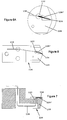
- Figures 6, 6A (in greater detail) and 7 show the ejection electrode 134 and its positioning within the cell 120 in detail.
- the ejection electrode 134 is mounted on an upstanding support 129' which is formed integrally with the side wall 129 of the housing 126 and the electrode 134 projects through the aperture 128 a distance of between 50 to 100 ⁇ m (see Figure 14A also).
- An electrical connection is provided by a wire 138 which passes into the cavity 121 though a further aperture 137 in the side wall 129, the aperture being epoxy filled during assembly in order to pot the wire in place and seal the aperture 137.
- the insoluble particles acquire a charge due to the action of a particle charging agent which ionises in solution, with the result that the insoluble particles acquire a charge and counter ions are formed of equal and opposite charge.
- a particle charging agent which ionises in solution
- This mechanism is well-known in the field of liquid toners, eg for photocopiers, and electrophoretic displays.
- the respective charges on the electrophoretic electrode 131 and the ejection electrode cause the ink particles to move electrophoretically towards the ejection electrode. Since the electrophoretic electrode 131 is in contact with the ink within the cell, through the contact 135, the potential of the ink at equilibrium will be the same as that of the electrophoretic electrode 131. This results in a net concentration of particles near the ejection electrode 134.
- an ejection pulse (pulses are of 200V to 1.5kV, of duration 50 to 200 ⁇ s, and may be at a frequency of 1 to 10kHz) is applied to the ejection electrode 134, ink particles are ejected (in the manner described in PCT/AU92/00665) onto the surface 136 (together possibly with a small quantity of the carrier liquid adhering to the particles) and the electrostatic equilibrium is disturbed, resulting in continued movement of particles to restore the depletion around the ejection electrode and maintain the concentration.
- pulse pulses are of 200V to 1.5kV, of duration 50 to 200 ⁇ s, and may be at a frequency of 1 to 10kHz
- Ink is fed into the cell through the inlet 123 in the side plate 129 to ensure a constant supply of ink particles to the cell in the low concentration region between the inlet and the outlet 124, whereby particles can be concentrated into the region around the ejection electrode 134.
- the flow rate in the high concentration region around the ejection electrode is low, thus ensuring that particles which have been concentrated by the field are not subsequently swept away by the bulk liquid flow in these regions.
- the electrophoretic electrode 131 is held at a positive (in this case) potential higher than the time-averaged potential of the ejection electrode 134.
- the ink used preferably conforms to the ink described in PCT/AU94/00357, ie comprising a carrier liquid having a high electrical resistance (eg > 10 9 ⁇ .cm) and insoluble marking particles dispersed within the carrier. Soluble or partially soluble resins or the like may be incorporated to disperse the marking particles and to function to bind the particle to a print surface in use. In addition, charge modifying agents may be included to assist the charging process.
- a mechanism has been identified which is a combination of a transport process which concentrates the particulates in a carrier fluid and a separate process (which can be an ejection process) which transfers them out of the carrier fluid.
- This appendix outlines the modelling work which has been carried out on the particle transport processes.
- a particle moving along the surface of a liquid experiences a reduced viscous drag as compared with a particle in the body of a liquid.
- the viscous drag is dependent on the detailed interaction of the particle with the surface of the liquid.
- the magnitude of the effective viscosity is not usually known, although we may postulate that it lies somewhere between the viscosity of the liquid and the viscosity of air.
- a list of potentials along the outside of the electrode was obtained from finite element field modelling. An interpolating function was fitted to the tangential potential distribution to obtain E tangential as a function of distance along the electrode.
- ⁇ the effective viscosity experienced by the particles
- x(t) the position of the particle along the surface of the liquid at time t.
- the equation was solved numerically for viscosities ranging between that of the carrier fluid and that of air - effectively zero.
- This force is of fundamental significance in the neighbourhood of the ejection point, since the electric force on the particles is primarily responsible for separating them out of the suspending fluid.
- this force on the particles can, if the physical boundaries of the fluid allow it, produce bulk motion in the fluid. This comes about because the viscous drag the fluid exerts on the particles corresponds to a transport of momentum from the particles to the fluid and this is equivalent to the action of a force at the centre of drag of the particle. Acting on a distributed set of particles, this amounts to a body force on the fluid. It will be shown that this motion can be useful as a means of bulk transport.
- the mechanism is important because the removal of particles establishes concentration gradients down which particles may try to diffuse. In practice, however, the effect is small and it has not been observed to be a major part of the replenishment process.
- the dielectric force will generally be much weaker than the electrophoretic force exerted on the charge in the same electric field.
- the dielectrophoretic effect may be significant.
- the direction of the force is towards higher field intensity, irrespective of the field's direction.
- the dielectrophoretic force acts against the electrophoretic force.
- Figure 11 shows a conceptual model of a head which is electrophoretically replenished. Particles are lost from the ejection point at a rate which is determined by the printing rate requirements. The ejected particles must be replenished by particles held in the bulk of the ink storage. At any position, x, along the head there are defined the following quantities:
- the electric field required to maintain the flow of particles is of the form: E(x) ⁇ ⁇ (x) k 0 f 0 d 3 Q/M(x) a(x) r(x) k(x)
- Q/M(x) is the charge to mass ratio of the particles
- d is the ejected droplet diameter and the other quantities are as defined below.
- the electric field required to transport the particles can be reduced by appropriate design of the particle mobility and by varying the cross-sectional area of the fluid reservoir. High mobility particles can be transported more rapidly with a given field. Varying the cross-sectional area reduces the field required by providing a larger number of particles per unit length of the reservoir. Reducing the electrophoretic field is desirable since this reduces the integrated field along the length of the reservoir and hence the maximum voltage required on the head.
- ink storage is shown at 201 and an ejection point at 202 in a coordinate system x-y as shown.
- the particles removed through 202 have the parameters:
- the rate of particle removal is equal to: 4 3 . ⁇ .r0 3 .k0.f0
Landscapes
- Chemical & Material Sciences (AREA)
- Chemical Kinetics & Catalysis (AREA)
- Physics & Mathematics (AREA)
- General Physics & Mathematics (AREA)
- Health & Medical Sciences (AREA)
- Life Sciences & Earth Sciences (AREA)
- Engineering & Computer Science (AREA)
- Electrochemistry (AREA)
- Environmental & Geological Engineering (AREA)
- Molecular Biology (AREA)
- Electrostatic Separation (AREA)
- Particle Formation And Scattering Control In Inkjet Printers (AREA)
- Feeding, Discharge, Calcimining, Fusing, And Gas-Generation Devices (AREA)
- Glass Compositions (AREA)
- Control And Other Processes For Unpacking Of Materials (AREA)
- Die Bonding (AREA)
- Analysing Materials By The Use Of Radiation (AREA)
- Seal Device For Vehicle (AREA)
- Inks, Pencil-Leads, Or Crayons (AREA)
- Fish Paste Products (AREA)
- Crystals, And After-Treatments Of Crystals (AREA)
- Ink Jet (AREA)
Applications Claiming Priority (3)
| Application Number | Priority Date | Filing Date | Title |
|---|---|---|---|
| GB9410558A GB9410558D0 (en) | 1994-05-26 | 1994-05-26 | Method of transferring matter from a bulk medium |
| GB9410558 | 1994-05-26 | ||
| EP95919581A EP0760746B1 (de) | 1994-05-26 | 1995-05-26 | Verfahren zum übertragen von material aus einem mittel |
Related Parent Applications (1)
| Application Number | Title | Priority Date | Filing Date |
|---|---|---|---|
| EP95919581A Division EP0760746B1 (de) | 1994-05-26 | 1995-05-26 | Verfahren zum übertragen von material aus einem mittel |
Publications (2)
| Publication Number | Publication Date |
|---|---|
| EP0875805A1 true EP0875805A1 (de) | 1998-11-04 |
| EP0875805B1 EP0875805B1 (de) | 2001-07-25 |
Family
ID=10755749
Family Applications (2)
| Application Number | Title | Priority Date | Filing Date |
|---|---|---|---|
| EP98109170A Expired - Lifetime EP0875805B1 (de) | 1994-05-26 | 1995-05-26 | Vorrichtung zur Massenübertragung |
| EP95919581A Expired - Lifetime EP0760746B1 (de) | 1994-05-26 | 1995-05-26 | Verfahren zum übertragen von material aus einem mittel |
Family Applications After (1)
| Application Number | Title | Priority Date | Filing Date |
|---|---|---|---|
| EP95919581A Expired - Lifetime EP0760746B1 (de) | 1994-05-26 | 1995-05-26 | Verfahren zum übertragen von material aus einem mittel |
Country Status (12)
| Country | Link |
|---|---|
| US (1) | US6019455A (de) |
| EP (2) | EP0875805B1 (de) |
| JP (1) | JP4020960B2 (de) |
| KR (1) | KR100360354B1 (de) |
| CN (1) | CN1077848C (de) |
| AT (2) | ATE203600T1 (de) |
| AU (2) | AU682773B2 (de) |
| CA (1) | CA2190942C (de) |
| DE (2) | DE69521918T2 (de) |
| GB (1) | GB9410558D0 (de) |
| RU (1) | RU2141898C1 (de) |
| WO (1) | WO1995032864A1 (de) |
Families Citing this family (19)
| Publication number | Priority date | Publication date | Assignee | Title |
|---|---|---|---|---|
| JP2783220B2 (ja) * | 1995-10-30 | 1998-08-06 | 日本電気株式会社 | インクジェット式記録ヘッド |
| GB9601212D0 (en) | 1996-01-22 | 1996-03-20 | The Technology Partnership Plc | Inkjet printer nozzle plate |
| GB9601223D0 (en) * | 1996-01-22 | 1996-03-20 | The Technology Partnership Plc | Electrode for printer |
| DE69702079T2 (de) | 1996-01-29 | 2000-10-05 | Nec Corp., Tokio/Tokyo | Preiswerter und einfacher elektrostatischer Tintenstrahldruckkopf |
| US6312104B1 (en) | 1998-06-17 | 2001-11-06 | Xerox Corporation | Reduction of spot misplacement through electrostatic focusing of uncharged drops |
| CA2409402A1 (en) * | 2000-06-14 | 2001-12-20 | Board Of Regents, The University Of Texas System | Apparatus and method for fluid injection |
| GB0130235D0 (en) * | 2001-12-18 | 2002-02-06 | Deltadot Ltd | Centrifugal spectrometer |
| MXPA03002490A (es) * | 2002-03-20 | 2004-10-15 | Seiko Epson Corp | Cartucho para tinta y soporte de cartucho para tinta. |
| JP4517123B2 (ja) * | 2002-12-25 | 2010-08-04 | クラスターテクノロジー株式会社 | 液体試料吐出方法およびその装置 |
| JP4407416B2 (ja) * | 2003-07-31 | 2010-02-03 | 国立大学法人京都大学 | 析出方法 |
| US20050153243A1 (en) * | 2004-01-09 | 2005-07-14 | Kodak Polychrome Graphics Llc | Ink-jet formation of flexographic printing plates |
| JP4125279B2 (ja) | 2004-10-20 | 2008-07-30 | キヤノン株式会社 | インクタンク、該インクタンクを搭載するホルダを備えたインクジェット記録装置およびインクタンクとホルダとを備えたインクジェット記録システム |
| WO2008130977A2 (en) | 2007-04-16 | 2008-10-30 | The General Hospital Corporation D/B/A Massachusetts General Hospital | Systems and methods for particle focusing in microchannels |
| EP2546656B8 (de) * | 2010-02-09 | 2019-06-12 | Microjet Corporation | Entladungsvorrichtung für ein partikelhaltiges flüssigmaterial |
| IL212441A (en) * | 2011-04-17 | 2015-08-31 | Green Gold 2007 Ltd | Centrifuge |
| EP3841435B1 (de) | 2018-11-29 | 2023-12-27 | Hewlett-Packard Development Company, L.P. | Flüssigkeitsträgerfiltration |
| US20220146962A1 (en) * | 2019-07-31 | 2022-05-12 | Hewlett-Packard Development Company, L.P. | Carrier liquid filtration utilizing electric fields |
| CN113109107B (zh) * | 2021-03-24 | 2022-06-07 | 西安交通大学 | 一种气溶胶颗粒的富集装置 |
| CN113245901B (zh) * | 2021-06-28 | 2022-03-04 | 浙江重力智能装备有限公司 | 一种数控机床用冷却液清理装置 |
Citations (4)
| Publication number | Priority date | Publication date | Assignee | Title |
|---|---|---|---|---|
| JPS6157343A (ja) * | 1984-08-29 | 1986-03-24 | Toshiba Corp | インクジエツト記録装置 |
| US4717926A (en) * | 1985-11-09 | 1988-01-05 | Minolta Camera Kabushiki Kaisha | Electric field curtain force printer |
| JPH02160557A (ja) * | 1988-12-14 | 1990-06-20 | Minolta Camera Co Ltd | インクジェットプリンタ |
| US5144340A (en) * | 1989-03-10 | 1992-09-01 | Minolta Camera Kabushiki Kaisha | Inkjet printer with an electric curtain force |
Family Cites Families (18)
| Publication number | Priority date | Publication date | Assignee | Title |
|---|---|---|---|---|
| GB1186184A (en) * | 1966-03-23 | 1970-04-02 | Nat Res Dev | Improvements in or relating to Separation Apparatus. |
| US3909383A (en) * | 1969-04-24 | 1975-09-30 | Xerox Corp | Cleaning process |
| CH562631A5 (en) * | 1973-03-17 | 1975-06-13 | Lutz Hans | Molecule sized particles esp. blood cells continuously septd. - by force field transference between parallel flows in direct contact |
| FR2232192A5 (en) * | 1973-05-30 | 1974-12-27 | Mishima Kosan Co Ltd | Ink release system for dot printer - magnetic fields are applied to ink in tube to oscillate or eject the ink |
| US4011157A (en) * | 1976-01-30 | 1977-03-08 | International Business Machines Corporation | Ultrasonic removal of solid impurities from recirculating ink |
| GB2098498B (en) * | 1980-10-27 | 1984-08-22 | Secr Defence | Separating particles from fluid |
| JPH064336Y2 (ja) * | 1985-03-25 | 1994-02-02 | 株式会社コパル | フイルム感度の自動読み込み機構を備えたカメラ用シャッタ装置 |
| JP2593434B2 (ja) * | 1985-06-29 | 1997-03-26 | 株式会社東芝 | 記録装置 |
| AT389235B (de) * | 1987-05-19 | 1989-11-10 | Stuckart Wolfgang | Verfahren zur reinigung von fluessigkeiten mittels ultraschall und vorrichtungen zur durchfuehrung dieses verfahrens |
| US4893886A (en) * | 1987-09-17 | 1990-01-16 | American Telephone And Telegraph Company | Non-destructive optical trap for biological particles and method of doing same |
| US4928125A (en) * | 1987-09-24 | 1990-05-22 | Minolta Camera Kabushiki Kaisha | Liquid drop ejection apparatus using a magnetic fluid |
| DE3742292C1 (de) * | 1987-12-14 | 1989-06-01 | Johann Prof Dr-Ing Stichlmair | Verfahren und Vorrichtung zur Zweiphasen-Elektrophorese |
| US5053824A (en) * | 1990-04-16 | 1991-10-01 | Xerox Corporation | Scavengeless development apparatus having a donor belt |
| GB2259276B (en) * | 1991-09-06 | 1995-09-27 | Linx Printing Tech | Ink jet printer |
| US5172170A (en) * | 1992-03-13 | 1992-12-15 | Xerox Corporation | Electroded donor roll for a scavengeless developer unit |
| GB9208357D0 (en) * | 1992-04-16 | 1992-06-03 | British Tech Group | Apparatus for separating a mixture |
| US5339142A (en) * | 1992-07-30 | 1994-08-16 | Xerox Corporation | AC/DC spatially programmable donor roll for xerographic development |
| JP2672806B2 (ja) | 1996-03-11 | 1997-11-05 | 株式会社東芝 | 記録方法 |
-
1994
- 1994-05-26 GB GB9410558A patent/GB9410558D0/en active Pending
-
1995
- 1995-05-26 DE DE69521918T patent/DE69521918T2/de not_active Expired - Lifetime
- 1995-05-26 EP EP98109170A patent/EP0875805B1/de not_active Expired - Lifetime
- 1995-05-26 RU RU96124488A patent/RU2141898C1/ru active
- 1995-05-26 AU AU25356/95A patent/AU682773B2/en not_active Expired
- 1995-05-26 WO PCT/GB1995/001215 patent/WO1995032864A1/en not_active Ceased
- 1995-05-26 JP JP50049696A patent/JP4020960B2/ja not_active Expired - Lifetime
- 1995-05-26 AT AT98109170T patent/ATE203600T1/de not_active IP Right Cessation
- 1995-05-26 AT AT95919581T patent/ATE174843T1/de not_active IP Right Cessation
- 1995-05-26 EP EP95919581A patent/EP0760746B1/de not_active Expired - Lifetime
- 1995-05-26 US US08/737,979 patent/US6019455A/en not_active Expired - Lifetime
- 1995-05-26 CA CA002190942A patent/CA2190942C/en not_active Expired - Lifetime
- 1995-05-26 CN CN95193681A patent/CN1077848C/zh not_active Expired - Lifetime
- 1995-05-26 KR KR1019960706688A patent/KR100360354B1/ko not_active Expired - Lifetime
- 1995-05-26 DE DE69506859T patent/DE69506859T2/de not_active Expired - Lifetime
-
1997
- 1997-12-16 AU AU48423/97A patent/AU710958B2/en not_active Ceased
Patent Citations (4)
| Publication number | Priority date | Publication date | Assignee | Title |
|---|---|---|---|---|
| JPS6157343A (ja) * | 1984-08-29 | 1986-03-24 | Toshiba Corp | インクジエツト記録装置 |
| US4717926A (en) * | 1985-11-09 | 1988-01-05 | Minolta Camera Kabushiki Kaisha | Electric field curtain force printer |
| JPH02160557A (ja) * | 1988-12-14 | 1990-06-20 | Minolta Camera Co Ltd | インクジェットプリンタ |
| US5144340A (en) * | 1989-03-10 | 1992-09-01 | Minolta Camera Kabushiki Kaisha | Inkjet printer with an electric curtain force |
Non-Patent Citations (2)
| Title |
|---|
| PATENT ABSTRACTS OF JAPAN vol. 010, no. 218 (M - 503) 30 July 1986 (1986-07-30) * |
| PATENT ABSTRACTS OF JAPAN vol. 014, no. 416 (M - 1021) 7 September 1990 (1990-09-07) * |
Also Published As
| Publication number | Publication date |
|---|---|
| DE69521918T2 (de) | 2002-03-28 |
| CA2190942C (en) | 2005-06-28 |
| DE69506859T2 (de) | 1999-05-20 |
| AU710958B2 (en) | 1999-09-30 |
| AU682773B2 (en) | 1997-10-16 |
| ATE203600T1 (de) | 2001-08-15 |
| RU2141898C1 (ru) | 1999-11-27 |
| JPH10500912A (ja) | 1998-01-27 |
| AU4842397A (en) | 1998-03-26 |
| GB9410558D0 (en) | 1994-07-13 |
| AU2535695A (en) | 1995-12-21 |
| EP0760746A1 (de) | 1997-03-12 |
| CN1077848C (zh) | 2002-01-16 |
| KR100360354B1 (ko) | 2003-05-16 |
| EP0760746B1 (de) | 1998-12-23 |
| WO1995032864A1 (en) | 1995-12-07 |
| ATE174843T1 (de) | 1999-01-15 |
| DE69521918D1 (de) | 2001-08-30 |
| US6019455A (en) | 2000-02-01 |
| CN1151134A (zh) | 1997-06-04 |
| EP0875805B1 (de) | 2001-07-25 |
| DE69506859D1 (de) | 1999-02-04 |
| CA2190942A1 (en) | 1995-12-07 |
| JP4020960B2 (ja) | 2007-12-12 |
Similar Documents
| Publication | Publication Date | Title |
|---|---|---|
| EP0875805A1 (de) | Vorrichtung zur Massenübertragung | |
| EP0407153B1 (de) | Elektrostatisches Druckgerät | |
| DE3789488T2 (de) | Direktes elektrostatisches Druckgerät und Druckkopfreinigungseinrichtung dafür. | |
| US4912489A (en) | Direct electrostatic printing apparatus with toner supply-side control electrodes | |
| AU702529B2 (en) | Apparatus and method for supplying material to a substrate | |
| DE3750074T2 (de) | Direktes elektrostatisches Druckgerät und Toner-Entwicklerzufuhreinrichtung dafür. | |
| US4876561A (en) | Printing apparatus and toner/developer delivery system therefor | |
| EP0494454B1 (de) | Gerät und Verfahren zum Auftragen eines nichtmagnetischen und nichtleitfähigen Toners | |
| US6836304B2 (en) | Method of manufacturing an image display medium capable of displaying an image repeatedly, and image display medium capable of displaying an image repeatedly | |
| US5106468A (en) | Electrophoretic separation | |
| US4985732A (en) | Electrostatic separator | |
| EP0415700B1 (de) | Vorrichtung zur Aussonderung von falsch geladenem Toner bei einem direkten elektrostatischen Druckgerät | |
| US4923581A (en) | Toner recycling by counterflow | |
| JPH0647298B2 (ja) | 粉体画像記録方法 | |
| EP0458579B1 (de) | Elektrostatisches Markieren | |
| US7300139B2 (en) | Ink jet recording apparatus using charged fine particle-containing ink | |
| JPS62257893A (ja) | 直接記録方式の現像粉体処理方式並びにその構成 | |
| JPS63254484A (ja) | 現像面清掃方法 |
Legal Events
| Date | Code | Title | Description |
|---|---|---|---|
| PUAI | Public reference made under article 153(3) epc to a published international application that has entered the european phase |
Free format text: ORIGINAL CODE: 0009012 |
|
| 17P | Request for examination filed |
Effective date: 19980605 |
|
| AC | Divisional application: reference to earlier application |
Ref document number: 760746 Country of ref document: EP |
|
| AK | Designated contracting states |
Kind code of ref document: A1 Designated state(s): AT BE CH DE DK ES FR GB GR IE IT LI LU MC NL PT SE |
|
| AX | Request for extension of the european patent |
Free format text: LT PAYMENT 980605;LV PAYMENT 980605;SI PAYMENT 980605 |
|
| 17Q | First examination report despatched |
Effective date: 19991012 |
|
| GRAG | Despatch of communication of intention to grant |
Free format text: ORIGINAL CODE: EPIDOS AGRA |
|
| GRAG | Despatch of communication of intention to grant |
Free format text: ORIGINAL CODE: EPIDOS AGRA |
|
| GRAG | Despatch of communication of intention to grant |
Free format text: ORIGINAL CODE: EPIDOS AGRA |
|
| GRAH | Despatch of communication of intention to grant a patent |
Free format text: ORIGINAL CODE: EPIDOS IGRA |
|
| GRAH | Despatch of communication of intention to grant a patent |
Free format text: ORIGINAL CODE: EPIDOS IGRA |
|
| GRAA | (expected) grant |
Free format text: ORIGINAL CODE: 0009210 |
|
| AC | Divisional application: reference to earlier application |
Ref document number: 760746 Country of ref document: EP |
|
| AK | Designated contracting states |
Kind code of ref document: B1 Designated state(s): AT BE CH DE DK ES FR GB GR IE IT LI LU MC NL PT SE |
|
| AX | Request for extension of the european patent |
Free format text: LT PAYMENT 19980605;LV PAYMENT 19980605;SI PAYMENT 19980605 |
|
| LTIE | Lt: invalidation of european patent or patent extension | ||
| PG25 | Lapsed in a contracting state [announced via postgrant information from national office to epo] |
Ref country code: NL Free format text: LAPSE BECAUSE OF FAILURE TO SUBMIT A TRANSLATION OF THE DESCRIPTION OR TO PAY THE FEE WITHIN THE PRESCRIBED TIME-LIMIT Effective date: 20010725 Ref country code: LI Free format text: LAPSE BECAUSE OF FAILURE TO SUBMIT A TRANSLATION OF THE DESCRIPTION OR TO PAY THE FEE WITHIN THE PRESCRIBED TIME-LIMIT Effective date: 20010725 Ref country code: IT Free format text: LAPSE BECAUSE OF FAILURE TO SUBMIT A TRANSLATION OF THE DESCRIPTION OR TO PAY THE FEE WITHIN THE PRE;WARNING: LAPSES OF ITALIAN PATENTS WITH EFFECTIVE DATE BEFORE 2007 MAY HAVE OCCURRED AT ANY TIME BEFORE 2007. THE CORRECT EFFECTIVE DATE MAY BE DIFFERENT FROM THE ONE RECORDED.SCRIBED TIME-LIMIT Effective date: 20010725 Ref country code: CH Free format text: LAPSE BECAUSE OF FAILURE TO SUBMIT A TRANSLATION OF THE DESCRIPTION OR TO PAY THE FEE WITHIN THE PRESCRIBED TIME-LIMIT Effective date: 20010725 Ref country code: BE Free format text: LAPSE BECAUSE OF FAILURE TO SUBMIT A TRANSLATION OF THE DESCRIPTION OR TO PAY THE FEE WITHIN THE PRESCRIBED TIME-LIMIT Effective date: 20010725 Ref country code: AT Free format text: LAPSE BECAUSE OF FAILURE TO SUBMIT A TRANSLATION OF THE DESCRIPTION OR TO PAY THE FEE WITHIN THE PRESCRIBED TIME-LIMIT Effective date: 20010725 |
|
| REF | Corresponds to: |
Ref document number: 203600 Country of ref document: AT Date of ref document: 20010815 Kind code of ref document: T |
|
| REG | Reference to a national code |
Ref country code: CH Ref legal event code: EP |
|
| REG | Reference to a national code |
Ref country code: IE Ref legal event code: FG4D |
|
| REF | Corresponds to: |
Ref document number: 69521918 Country of ref document: DE Date of ref document: 20010830 |
|
| PG25 | Lapsed in a contracting state [announced via postgrant information from national office to epo] |
Ref country code: SE Free format text: LAPSE BECAUSE OF FAILURE TO SUBMIT A TRANSLATION OF THE DESCRIPTION OR TO PAY THE FEE WITHIN THE PRESCRIBED TIME-LIMIT Effective date: 20011025 Ref country code: PT Free format text: LAPSE BECAUSE OF FAILURE TO SUBMIT A TRANSLATION OF THE DESCRIPTION OR TO PAY THE FEE WITHIN THE PRESCRIBED TIME-LIMIT Effective date: 20011025 Ref country code: DK Free format text: LAPSE BECAUSE OF FAILURE TO SUBMIT A TRANSLATION OF THE DESCRIPTION OR TO PAY THE FEE WITHIN THE PRESCRIBED TIME-LIMIT Effective date: 20011025 |
|
| PG25 | Lapsed in a contracting state [announced via postgrant information from national office to epo] |
Ref country code: GR Free format text: LAPSE BECAUSE OF FAILURE TO SUBMIT A TRANSLATION OF THE DESCRIPTION OR TO PAY THE FEE WITHIN THE PRESCRIBED TIME-LIMIT Effective date: 20011026 |
|
| EN | Fr: translation not filed | ||
| REG | Reference to a national code |
Ref country code: GB Ref legal event code: IF02 |
|
| NLV1 | Nl: lapsed or annulled due to failure to fulfill the requirements of art. 29p and 29m of the patents act | ||
| PG25 | Lapsed in a contracting state [announced via postgrant information from national office to epo] |
Ref country code: ES Free format text: LAPSE BECAUSE OF FAILURE TO SUBMIT A TRANSLATION OF THE DESCRIPTION OR TO PAY THE FEE WITHIN THE PRESCRIBED TIME-LIMIT Effective date: 20020131 |
|
| REG | Reference to a national code |
Ref country code: CH Ref legal event code: PL |
|
| EN | Fr: translation not filed |
Free format text: BO 01/51 PAGES: 265, IL Y A LIEU DE SUPPRIMER: LA MENTION DE LA NON REMISE. LA REMISE EST PUBLIEE DANS LE PRESENT BOPI. |
|
| ET | Fr: translation filed | ||
| PG25 | Lapsed in a contracting state [announced via postgrant information from national office to epo] |
Ref country code: MC Free format text: LAPSE BECAUSE OF NON-PAYMENT OF DUE FEES Effective date: 20020526 Ref country code: LU Free format text: LAPSE BECAUSE OF NON-PAYMENT OF DUE FEES Effective date: 20020526 |
|
| PG25 | Lapsed in a contracting state [announced via postgrant information from national office to epo] |
Ref country code: IE Free format text: LAPSE BECAUSE OF NON-PAYMENT OF DUE FEES Effective date: 20020527 |
|
| PLBE | No opposition filed within time limit |
Free format text: ORIGINAL CODE: 0009261 |
|
| STAA | Information on the status of an ep patent application or granted ep patent |
Free format text: STATUS: NO OPPOSITION FILED WITHIN TIME LIMIT |
|
| 26N | No opposition filed | ||
| REG | Reference to a national code |
Ref country code: IE Ref legal event code: MM4A |
|
| REG | Reference to a national code |
Ref country code: GB Ref legal event code: 732E |
|
| REG | Reference to a national code |
Ref country code: GB Ref legal event code: 732E |
|
| REG | Reference to a national code |
Ref country code: FR Ref legal event code: TP |
|
| PGFP | Annual fee paid to national office [announced via postgrant information from national office to epo] |
Ref country code: DE Payment date: 20120523 Year of fee payment: 18 |
|
| PGFP | Annual fee paid to national office [announced via postgrant information from national office to epo] |
Ref country code: FR Payment date: 20120608 Year of fee payment: 18 Ref country code: GB Payment date: 20120523 Year of fee payment: 18 |
|
| GBPC | Gb: european patent ceased through non-payment of renewal fee |
Effective date: 20130526 |
|
| PG25 | Lapsed in a contracting state [announced via postgrant information from national office to epo] |
Ref country code: DE Free format text: LAPSE BECAUSE OF NON-PAYMENT OF DUE FEES Effective date: 20131203 |
|
| REG | Reference to a national code |
Ref country code: DE Ref legal event code: R119 Ref document number: 69521918 Country of ref document: DE Effective date: 20131203 |
|
| REG | Reference to a national code |
Ref country code: FR Ref legal event code: ST Effective date: 20140131 |
|
| PG25 | Lapsed in a contracting state [announced via postgrant information from national office to epo] |
Ref country code: GB Free format text: LAPSE BECAUSE OF NON-PAYMENT OF DUE FEES Effective date: 20130526 |
|
| PG25 | Lapsed in a contracting state [announced via postgrant information from national office to epo] |
Ref country code: FR Free format text: LAPSE BECAUSE OF NON-PAYMENT OF DUE FEES Effective date: 20130531 |