EP0875985A2 - Générateur de haute tension avec une unité de haute tension - Google Patents
Générateur de haute tension avec une unité de haute tension Download PDFInfo
- Publication number
- EP0875985A2 EP0875985A2 EP98201335A EP98201335A EP0875985A2 EP 0875985 A2 EP0875985 A2 EP 0875985A2 EP 98201335 A EP98201335 A EP 98201335A EP 98201335 A EP98201335 A EP 98201335A EP 0875985 A2 EP0875985 A2 EP 0875985A2
- Authority
- EP
- European Patent Office
- Prior art keywords
- voltage
- unit
- point
- connection point
- connection
- Prior art date
- Legal status (The legal status is an assumption and is not a legal conclusion. Google has not performed a legal analysis and makes no representation as to the accuracy of the status listed.)
- Withdrawn
Links
- 238000004804 winding Methods 0.000 claims description 30
- 230000003321 amplification Effects 0.000 claims description 12
- 238000003199 nucleic acid amplification method Methods 0.000 claims description 12
- 239000003990 capacitor Substances 0.000 description 11
- 238000010586 diagram Methods 0.000 description 6
- 238000010079 rubber tapping Methods 0.000 description 2
- 230000005540 biological transmission Effects 0.000 description 1
- 230000000694 effects Effects 0.000 description 1
- 238000009499 grossing Methods 0.000 description 1
- 230000010363 phase shift Effects 0.000 description 1
- 230000009466 transformation Effects 0.000 description 1
Images



Classifications
-
- H—ELECTRICITY
- H02—GENERATION; CONVERSION OR DISTRIBUTION OF ELECTRIC POWER
- H02M—APPARATUS FOR CONVERSION BETWEEN AC AND AC, BETWEEN AC AND DC, OR BETWEEN DC AND DC, AND FOR USE WITH MAINS OR SIMILAR POWER SUPPLY SYSTEMS; CONVERSION OF DC OR AC INPUT POWER INTO SURGE OUTPUT POWER; CONTROL OR REGULATION THEREOF
- H02M7/00—Conversion of AC power input into DC power output; Conversion of DC power input into AC power output
- H02M7/02—Conversion of AC power input into DC power output without possibility of reversal
- H02M7/04—Conversion of AC power input into DC power output without possibility of reversal by static converters
- H02M7/06—Conversion of AC power input into DC power output without possibility of reversal by static converters using discharge tubes without control electrode or semiconductor devices without control electrode
- H02M7/10—Conversion of AC power input into DC power output without possibility of reversal by static converters using discharge tubes without control electrode or semiconductor devices without control electrode arranged for operation in series, e.g. for multiplication of voltage
- H02M7/103—Containing passive elements (capacitively coupled) which are ordered in cascade on one source
-
- H—ELECTRICITY
- H03—ELECTRONIC CIRCUITRY
- H03K—PULSE TECHNIQUE
- H03K3/00—Circuits for generating electric pulses; Monostable, bistable or multistable circuits
- H03K3/02—Generators characterised by the type of circuit or by the means used for producing pulses
- H03K3/53—Generators characterised by the type of circuit or by the means used for producing pulses by the use of an energy-accumulating element discharged through the load by a switching device controlled by an external signal and not incorporating positive feedback
-
- H—ELECTRICITY
- H02—GENERATION; CONVERSION OR DISTRIBUTION OF ELECTRIC POWER
- H02M—APPARATUS FOR CONVERSION BETWEEN AC AND AC, BETWEEN AC AND DC, OR BETWEEN DC AND DC, AND FOR USE WITH MAINS OR SIMILAR POWER SUPPLY SYSTEMS; CONVERSION OF DC OR AC INPUT POWER INTO SURGE OUTPUT POWER; CONTROL OR REGULATION THEREOF
- H02M1/00—Details of apparatus for conversion
- H02M1/0083—Converters characterised by their input or output configuration
- H02M1/009—Converters characterised by their input or output configuration having two or more independently controlled outputs
Definitions
- the invention relates to a high voltage generator with a High voltage unit for generating an output DC high voltage and with a voltage generating unit for generating at least one further, smaller DC high voltage, the voltage generating unit from the High voltage unit is supplied with a DC voltage and the Voltage generating unit an adjustment unit for setting the further DC high voltage in a voltage setting range between a lower and a has upper limit voltage.
- Such a high voltage generator is known from US Pat. No. 4,788,591.
- An output DC high voltage is generated there by means of a diode split transformer generated to supply the anode of a display tube.
- a setting unit comprising two potentiometers, two Generates voltages that are used to focus the electrons in the Display tubes serve.
- these voltages are adjustable in a setting range between a lower and an upper one Limit voltage, which is generally 20% and 29% for a display tube the output DC high voltage.
- One of the series Potentiometer is connected to a connection point of the high voltage unit, to which a DC voltage is applied.
- the base point of the second potentiometer is at one generally as a reference potential in a display tube serving DC voltage potential of 210 V.
- a voltage generating unit in which adjustable DC high voltages, for example for focusing electrons in a tube, in particular a picture display tube essentially through the required dielectric strength and power loss the setting unit, which has two potentiometers in the known arrangement, certainly.
- the setting unit In a picture display tube in which the output DC high voltage for example 25 kV and the lower and upper limit voltage about 5 kV or 7.25 kV, the setting unit must have a high dielectric strength exhibit.
- the invention is therefore based on the object of a high-voltage generator to improve the type mentioned, in particular one High voltage generator with low cost, small size and high To indicate efficiency.
- This task is based on the above High voltage generator solved in that means are provided for supply the adjustment unit at a connection point with a between 100% and 200% of the DC voltage and a further limit voltage Connection point with between 50% and 100% of the lower limit voltage lying DC voltage and that the means at least one connection with a Include DC voltage point of the high voltage unit, at which one between 50% of the lower limit voltage and 200% of the upper limit voltage DC voltage is present.
- the invention is based on the knowledge that the setting unit is not necessarily at a connection point with one that serves as reference potential Low voltage potential (e.g. ground) must be connected.
- the setting unit can in the arrangement according to the invention, a significantly lower dielectric strength than in the known arrangement, because a clearly above the setting unit there is less voltage difference.
- the voltage generating unit also has low impedance, causing changes in high DC voltages, caused by changes in current quantities, are as small as possible.
- a Use of the DC high voltages to focus the electrons in a Image display tube causes this focusing to remain extremely stable.
- Each closer the DC voltage present at the one connection point at 100% of the upper limit voltage and that at the other connection point DC voltage at 100% of the lower limit voltage the lower the Dielectric strength of the adjustment unit fail and the more advantageous the invention.
- connection point with a DC voltage point of the high-voltage unit is connected to a between 100% and 200% of the upper limit voltage DC voltage is present and that the further connection point with a Another DC voltage point of the high-voltage unit is connected to the a DC voltage between 50% and 100% of the lower limit voltage is present. It is thus achieved with simple means that a there is a small voltage difference.
- High voltage unit can use suitable DC voltage points High-voltage unit can be selected on which the setting unit is connected.
- the high voltage generator has a Transformer with a first secondary winding to generate the Input voltage of the high voltage unit has that the transformer has a second secondary winding with a rectifier circuit connected downstream, that the output connections of the rectifier circuit with one of each Connection points of the setting unit are connected and that one of the Connection points of the adjustment unit with a DC voltage point High-voltage unit is connected to which between 50% and 100% of the lower limit voltage or between 100% and 200% of the upper limit voltage DC voltage is present.
- This configuration is particularly suitable if a direct voltage can be taken from the high-voltage unit that is as accurate as possible corresponds to the upper or lower limit voltage, but no further DC voltage that corresponds to the other limit voltage. This is then done using the second secondary winding of the transformer, so that over the Adjustment unit only the maximum necessary voltage difference is present.
- the high voltage generator Transformer with a first secondary winding to generate the Input voltage of the high voltage unit has that the transformer Second secondary winding has a first connection point and a middle connection point of the secondary winding a first rectifier circuit is connected downstream, the first output connection with a first connection point the adjustment unit is connected and its second output connection with a DC voltage point of the high-voltage unit is connected, at which one in Voltage setting range lying DC voltage, and that a second Connection point and the middle connection point of the secondary winding a second Rectifier circuit is connected downstream, the first output connection with the second connection point of the setting unit is connected and the second Output connection with the same DC voltage point of the high voltage unit connected is.
- This configuration is particularly advantageous if the High voltage unit a DC voltage can be removed, which in Voltage adjustment range is, but no DC voltages that are exactly the same lower or upper limit voltage. From the in the voltage setting range lying DC voltage taken from the high-voltage unit are at derived from this configuration two voltage potentials that the upper or correspond to the lower limit voltage, so that again only via the setting unit the maximum necessary voltage difference is present.
- one of the connection points the setting unit with a DC voltage point of the high voltage unit is connected to a between 50% and 100% of the lower limit voltage or DC voltage between 100% and 200% of the upper limit voltage is present and that the means a voltage multiplier circuit, especially one High-voltage cascade multiplier circuit for generating a DC voltage from the input voltage of the high voltage unit Supply of the adjustment unit at the other connection point.
- This solution is suitable especially when a DC voltage can be taken from the high-voltage unit which corresponds exactly to the upper or lower limit voltage.
- the amplification factor of the voltage multiplier circuit then becomes one Generates DC voltage for the setting unit, that of the other Limit voltage corresponds, which can not be removed from the high-voltage unit. over The adjustment unit is only the maximum necessary in this training Voltage difference. This can otherwise be the one described above Avoid design of the transformer with a second secondary winding will.
- the setting unit has two potentiometers each for setting a DC high voltage. This is the easiest and The most cost-effective way to implement the setting unit. However, it does exist also the possibility of the adjustment unit or the functions of potentiometers to be realized by other circuitry means.
- the high voltage unit Cascade high voltage multiplier circuit or a diode split transformer circuit includes.
- the High voltage unit of a high voltage generator realized in this way.
- the number of amplification stages of such a high-voltage unit plays no role for the idea of the invention.
- means are provided for deriving a further DC voltage from one for generating the input voltage of the high-voltage unit AC voltage used.
- These funds can be, for example Potentiometer and an additional connection to the secondary winding of the Transformer, which is an AC voltage in the input voltage of the High voltage unit transformed.
- the potentiometer can also be used on a Gain stage of an additional high voltage cascade multiplier circuit to generate a DC voltage for the setting unit be connected.
- the invention also relates to an image display device having at least one Image display tube with focus electrode and with a High voltage generator with a high voltage unit for generating a Output DC high voltage and with a focus unit for generation at least a focus voltage, the focus unit comprising a high-voltage unit DC voltage is supplied and the focus unit is an adjustment unit for Setting the focus voltage in a voltage setting range between one lower and an upper limit voltage, which is characterized in that means are provided to supply the setting unit on one Connection point with a between 100% and 200% of the upper limit voltage lying DC voltage and at a further connection point with a between 50% and 100% of the lower limit voltage and that the At least one connection with a DC voltage point High voltage unit, one of which is between 50% of the lower Limit voltage and 200% of the upper limit voltage DC voltage is present.
- the focus unit is simple and inexpensive due to the invention realize.
- the low impedance of the focus unit also leads to low ones Dimensions, a higher efficiency and ultimately a very stable Focusing.
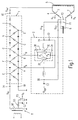
- the high-voltage unit 1 shows a circuit diagram of a first embodiment of a high-voltage generator according to the invention.
- the high-voltage unit 1 comprises a cascade-high-voltage multiplier circuit with ten amplification stages, which generates a symmetrical AC voltage U at the inputs 1A, 1B into a DC high voltage U out at the output 1C, which is ten times larger than that Amplitude of the input voltage U in .
- the symmetrical AC input voltage U in can be the voltage across the secondary winding W1 of the transformer T of a series-parallel resonant, frequency-variable converter (not shown).
- the DC output voltage U out of the high-voltage unit 1, which is, for example, 25 kV (relative to ground), serves to supply the anode 5 of a picture display tube 4 in order to accelerate the electrons emitted from the cathode 6.
- a focus unit 2 is provided to generate two focus voltages U F1 , U F2 for supplying the two focus electrodes F1, F2 of the image display tube 4.
- This has an adjustment unit 3, which enables the focus voltages U F1 , U F2 to be set in the adjustment range by means of two potentiometers P1, P2.
- the DC focus voltage U F1 for tapping the horizontal focus correction in the picture display tube 4 is tapped via a resistor, a smoothing capacitor being present between the connections 2A and 3A to reduce the ripple of the focus voltage U F1 .
- the direct voltage component for the focus voltage U F2 is tapped via a resistor, to which an alternating voltage component U dyn is superimposed via a capacitor C2 at the connection 2B to optimize vertical focusing in the image display tube 4.
- an adjustable shield voltage U S is tapped via a one-way rectifier circuit comprising a diode D3 and a capacitor C3 at a potentiometer P3, which is applied to further electron focusing means, for example deflection plates 7 of the image display tube 4.
- the required dielectric strength of the potentiometers P1, P2 can be significantly reduced compared to known designs and their dimensions can be significantly reduced.
- the losses in the potentiometers P1, P2 are significantly lower, since these losses are roughly proportional to the square of the voltage across the potentiometers P1, P2.
- the impedance of the focus unit 2 is also significantly lower than in known arrangements. It is thereby achieved that changes in the focus voltages U F1 , U F2 , which can be caused by changes in the focus current, are very small, so that the focusing remains very stable. Overall, the entire focus unit 2 is smaller and cheaper than known designs.
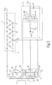
- FIG. 2 Another embodiment of a high voltage generator according to the invention is shown in Fig. 2. Different from the embodiment shown in FIG. 1 the one connected to the second connection point 3B of the setting unit 3 DC voltage is not taken from the high-voltage unit 1, but separately generated.
- the transformer T has a second secondary winding W2, which a voltage applied to the primary winding of the transformer T into a High voltage transformed. This is made with the diode D4 and the Capacitor C4 existing rectifier circuit 8 rectified, so that on Connection point 8A there is a DC high voltage to supply the Connection point 3B of the setting unit 3.
- the connection point 8B is advantageously with the DC voltage point A (and thus also with the Connection point 3A) connected.
- the voltage present between the connection points 8A and 8B can be set such that only the maximum necessary voltage difference is present across the potentiometers P1, P2.
- the transmission ratio can be selected so that a voltage of 0.29 * U out (against ground) is present at connection point 8A.
- a voltage of 0.2 * U out (to ground) is present at connection point 8B.
- the smallest possible voltage difference of 0.09 * U out is then applied via the potentiometers P1 and P2.
- the connections to the secondary winding 2 are preferably made so that the voltage tapped thereon is 180 ° out of phase with respect to the voltage tapped at the secondary winding W1, which is indicated by the point at the upper end next to W1 and at the lower end next to W2. It is thereby achieved that the ripple of the voltage U A present at the DC voltage point A is compensated for by the ripple in phase opposition at the connection point 8A.
- the ripple at the connection point 8A can be set to be the same as the ripple at the DC voltage point A, and thus the ripple of the focus voltages U F1 , U F2 can be minimized.
- the capacitance value of the capacitor C1 which otherwise also ensures a low-ripple focus voltage U F1 due to the filter effect, can be reduced.
- FIG. 3 A third embodiment of a high-voltage generator according to the invention is shown in FIG. 3.
- the high-voltage unit 1 ' is a cascade of eight.
- the voltage U A ' at the DC voltage point A' is 0.25 * U out and is thus almost in the middle of the setting range.
- the transformer T has a secondary winding W2 'with three connection points Z1, Z2, Z3, which are followed by two one-way rectifier circuits 91, 92.
- connection points 9A and 9C at which the direct voltage U A ' is present, a direct voltage is generated from the voltage tapped at the taps Z1 and Z3 by rectification by means of the diode D41 and the capacitor C41, which is equal to the voltage difference of the lowest focus voltage to be set and the voltage U A ' .
- the voltage potential at connection point 9A which is connected to connection point 3A of setting unit 3, is negative with respect to the voltage potential at connection point 9C.
- a voltage is generated between the connection points 9B and 9C which is equal to the voltage difference between the largest focus voltage to be set and the direct voltage U A ' .
- connection point 9B which is connected to the connection point 3B of the setting unit 3 is positive compared to the voltage potential at the connection point 9C. Only the voltage generated between the connection points 9A and 9B lies above the potentiometers P1, P2, which is the difference between the minimum and the maximum focus voltage to be set.
- the voltage across the capacitor C1 is a maximum of the focus voltage range to be set, a lower voltage being usually present.
- a ripple compensation can be achieved by phase shift.
- the capacity value of the Capacitor C1 can be reduced.
- FIG. 4 An alternative way of generating a suitable voltage for the connection point 3B of the setting unit 3 is shown in FIG. 4.
- the input terminal 3A is in turn connected to the DC voltage terminal A of a tenfold cascade 1.
- a separate triplet cascade 10 is provided, which generates a three-fold greater DC voltage at the output 10C from the AC voltage present at the input connections 1A, 1B of the ten-fold cascade 1.
- its internal resistance can be selected such that a voltage of 0.01 * U out drops across it, so that only the maximum necessary voltage of 0.09 * U out is present across the potentiometers P1, P2.
- the transformer T can be made much simpler and therefore cheaper, and can also be better optimized.
- the shield voltage U S can be tapped here by means of a potentiometer P3 'between the connection points 10B and 10D of the triplet cascade 10, as a result of which there is no need for complex tapping of the secondary winding W1 of the transformer T.
- the high-voltage unit 1 ′′ comprises a five-stage diode split transformer for generating the DC high voltage U out .
- This also generates from the AC voltage U present at the beginning into a DC voltage U out that is ten times larger.
- U A '' 0.2 * U out respectively.
- U B '' 0.4 * U out on.
- the focus voltage U F1 is also smoothed here by connecting the capacitances C1 and C5 in series.
- the capacitance C5 corresponds to the layer capacitance across the secondary winding W1 ′′ of the transformer T. Since the layer capacitance C5 in a diode-split transformer is often less than or approximately equal to the capacitance C1, a capacitor C6 can additionally be connected in parallel with C5. A resistor for current limiting can also be connected in series with the capacitor C6.
- the potentiometers P1, P2 of the setting unit 3 can also be adjusted by suitable ones circuitry means are realized, for example a Current mirror circuit, an RC low-pass circuit, a flyback transformer circuit or an adjustable tens diode circuit.
- the invention can also be used in high-voltage generators whose high-voltage unit has more or less amplification stages than the embodiments shown or in which the DC high voltage U out is generated at all by other means.
Landscapes
- Engineering & Computer Science (AREA)
- Power Engineering (AREA)
- Rectifiers (AREA)
- Coils Or Transformers For Communication (AREA)
- Details Of Television Scanning (AREA)
Applications Claiming Priority (2)
| Application Number | Priority Date | Filing Date | Title |
|---|---|---|---|
| DE19718656 | 1997-05-02 | ||
| DE19718656A DE19718656A1 (de) | 1997-05-02 | 1997-05-02 | Hochspannungsgenerator mit einer Hochspannungseinheit |
Publications (2)
| Publication Number | Publication Date |
|---|---|
| EP0875985A2 true EP0875985A2 (fr) | 1998-11-04 |
| EP0875985A3 EP0875985A3 (fr) | 2002-02-20 |
Family
ID=7828487
Family Applications (1)
| Application Number | Title | Priority Date | Filing Date |
|---|---|---|---|
| EP98201335A Withdrawn EP0875985A3 (fr) | 1997-05-02 | 1998-04-27 | Générateur de haute tension avec une unité de haute tension |
Country Status (6)
| Country | Link |
|---|---|
| US (1) | US6201359B1 (fr) |
| EP (1) | EP0875985A3 (fr) |
| JP (1) | JPH1127944A (fr) |
| KR (1) | KR19980086780A (fr) |
| DE (1) | DE19718656A1 (fr) |
| TW (1) | TW398143B (fr) |
Families Citing this family (7)
| Publication number | Priority date | Publication date | Assignee | Title |
|---|---|---|---|---|
| US7365518B2 (en) * | 2004-10-07 | 2008-04-29 | L-3 Communications Electron Technologies, Inc. | Ion engine power supply |
| MX2009000225A (es) * | 2006-06-26 | 2009-07-15 | Battelle Memorial Institute | Suministro de energia de alto voltaje. |
| US9808547B2 (en) | 2013-04-18 | 2017-11-07 | Dm Tec, Llc | Sanitizer |
| US9950086B2 (en) | 2014-03-12 | 2018-04-24 | Dm Tec, Llc | Fixture sanitizer |
| US9700643B2 (en) | 2014-05-16 | 2017-07-11 | Michael E. Robert | Sanitizer with an ion generator |
| US10124083B2 (en) | 2015-06-18 | 2018-11-13 | Dm Tec, Llc | Sanitizer with an ion generator and ion electrode assembly |
| EP4404453A1 (fr) * | 2023-01-20 | 2024-07-24 | Siemens Healthineers AG | Cascade haute tension |
Family Cites Families (18)
| Publication number | Priority date | Publication date | Assignee | Title |
|---|---|---|---|---|
| US3573539A (en) * | 1969-04-01 | 1971-04-06 | Gen Electric | Adjustable focus voltage supply for television receivers |
| DE2307227B2 (de) * | 1972-02-28 | 1980-05-22 | American Plasticraft Co., Chicago, Ill. (V.St.A.) | Hochspannungsvervielfacherbaugruppe für die Spannungsversorgung von Kathodenstrahlröhren |
| US3940789A (en) * | 1973-07-13 | 1976-02-24 | Kew, Incorporated | Multicolor display for the visual-aesthetic portrayal of electric signals |
| JPS5537854A (en) * | 1978-09-07 | 1980-03-17 | Sony Corp | Voltage multiplying high voltage rectifying circuit |
| EP0035758B1 (fr) * | 1980-03-10 | 1984-08-08 | Ernst Roederstein Spezialfabrik für Kondensatoren GmbH | Circuit pour la production de tensions d'alimentation destinées aux tubes images d'appareils de télévision |
| DE3318503C2 (de) * | 1983-05-20 | 1986-03-06 | Ernst Roederstein Spezialfabrik für Kondensatoren GmbH, 8300 Landshut | Generator zur Hochspannungserzeugung |
| GB2152336A (en) * | 1983-09-15 | 1985-07-31 | Sinclair Res Ltd | Television receivers |
| US4638220A (en) * | 1985-03-04 | 1987-01-20 | General Electric Company | High voltage transformer |
| FR2607991B1 (fr) | 1986-12-05 | 1989-02-03 | Radiotechnique Ind & Comm | Alimentation a decoupage pour un televiseur muni d'un systeme de veille |
| US4835668A (en) * | 1987-03-23 | 1989-05-30 | U. S. Philips Corporation | Power supply with two output voltages |
| DD278021A1 (de) * | 1988-12-12 | 1990-04-18 | Zentr Wissenschaft & Tech Veb | Schaltungsanordnung zur gewinnung der anoden- und der fokussierspannung fuer bildwiedergaberoehren |
| US5034666A (en) * | 1990-04-13 | 1991-07-23 | Thomson Consumer Electronics, Inc. | Power supply for an electrode of a CRT |
| US5576681A (en) * | 1990-12-10 | 1996-11-19 | Deutsche Thomson-Brandt Gmbh | High voltage transformer |
| JPH04268709A (ja) * | 1991-02-25 | 1992-09-24 | Matsushita Electric Ind Co Ltd | 高圧発生装置およびそのボリュームユニット |
| JPH05260751A (ja) * | 1992-03-09 | 1993-10-08 | Mitsubishi Electric Corp | フライバックトランス |
| JP2819956B2 (ja) * | 1992-08-31 | 1998-11-05 | 株式会社日立製作所 | Crt表示装置 |
| US5428272A (en) * | 1993-09-03 | 1995-06-27 | Thomson Consumer Electronics, Inc. | Voltage regulator for CRT electrode supply |
| US5602447A (en) * | 1994-08-03 | 1997-02-11 | Thomson Consumer Electronics, Inc. | Cathode ray tube focus supply |
-
1997
- 1997-05-02 DE DE19718656A patent/DE19718656A1/de not_active Withdrawn
-
1998
- 1998-04-15 TW TW087105711A patent/TW398143B/zh not_active IP Right Cessation
- 1998-04-16 US US09/062,776 patent/US6201359B1/en not_active Expired - Fee Related
- 1998-04-27 EP EP98201335A patent/EP0875985A3/fr not_active Withdrawn
- 1998-04-30 JP JP10120619A patent/JPH1127944A/ja active Pending
- 1998-05-02 KR KR1019980016088A patent/KR19980086780A/ko not_active Withdrawn
Also Published As
| Publication number | Publication date |
|---|---|
| JPH1127944A (ja) | 1999-01-29 |
| TW398143B (en) | 2000-07-11 |
| DE19718656A1 (de) | 1998-11-05 |
| EP0875985A3 (fr) | 2002-02-20 |
| US6201359B1 (en) | 2001-03-13 |
| KR19980086780A (ko) | 1998-12-05 |
Similar Documents
| Publication | Publication Date | Title |
|---|---|---|
| DE3218952C2 (de) | Gleichrichterschaltung | |
| EP0763276A1 (fr) | Alimentation electrique a decoupage destinee au fonctionnement de lampes electriques | |
| DE2911152A1 (de) | Zeilen(ablenk)transformator | |
| DE3036878A1 (de) | Modulator fuer eine ost-west-kissenkorrekturschaltung | |
| DE3047340C2 (fr) | ||
| EP0875985A2 (fr) | Générateur de haute tension avec une unité de haute tension | |
| EP0349743B1 (fr) | Amplificateur de puissance | |
| DE2331597C3 (de) | Hochspannungsgenerator | |
| DE1283878C2 (de) | Energierueckgewinnungsschaltung fuer die horizontalablenkstufe eines fernsehempfaengers | |
| EP0684688A1 (fr) | Générateur de puissance avec un transformateur | |
| DE1929443A1 (de) | Stromversorgung fuer eine Hochspannungsanordnung wie eine Bildverstaerkerroehre od.dgl. | |
| DE69516597T2 (de) | Fokussierspannungsversorgung für eine Kathodenstrahlröhre | |
| DE910673C (de) | Anordnung zur Zufuehrung von Betriebsspannungen an Schaltungsteile, die gegenueber ihrer Umgebung hohe Wechselspannungen fuehren | |
| DE1145670B (de) | Schaltungsanordnung zur dynamischen Nachfokussierung elektrostatisch fokussierter Elektronen-strahlroehren | |
| DE19536653A1 (de) | Hochspannungsgenerator | |
| DE835478C (de) | Schaltung zur Erzeugung einer hohen Gleichspannung | |
| DE3335154A1 (de) | Aufwaertstransformier-mehrfachgleichrichter- schaltung | |
| DE1904757C3 (de) | Zeilenausgangstransformator mit einer Wicklung zur Hochspannungserzeugung für Fernsehempfänger | |
| DE3318503C2 (de) | Generator zur Hochspannungserzeugung | |
| DE2537694C3 (de) | Anordnung zur Erzeugung einer hohen einstellbaren Gleichspannung in einem Fernsehgerät | |
| DE3437064A1 (de) | Mittelfrequenz-roentgengenerator | |
| DE2615863A1 (de) | Elektrischer transformator bestehend aus einem aktiven vierpol | |
| DE3708229C2 (fr) | ||
| DE2436742C3 (de) | Hochspannungsgenerator für Nachfokussier-Farbbildröhre | |
| EP0952759A1 (fr) | Transformateur électronique |
Legal Events
| Date | Code | Title | Description |
|---|---|---|---|
| PUAI | Public reference made under article 153(3) epc to a published international application that has entered the european phase |
Free format text: ORIGINAL CODE: 0009012 |
|
| AK | Designated contracting states |
Kind code of ref document: A2 Designated state(s): AT BE CH CY DE DK ES FI FR GB GR IE IT LI LU MC NL PT SE Kind code of ref document: A2 Designated state(s): DE FR GB |
|
| AX | Request for extension of the european patent |
Free format text: AL;LT;LV;MK;RO;SI |
|
| RAP3 | Party data changed (applicant data changed or rights of an application transferred) |
Owner name: KONINKLIJKE PHILIPS ELECTRONICS N.V. Owner name: PHILIPS CORPORATE INTELLECTUAL PROPERTY GMBH |
|
| RIC1 | Information provided on ipc code assigned before grant |
Free format text: 7H 02M 7/10 A, 7H 04N 5/63 B |
|
| PUAL | Search report despatched |
Free format text: ORIGINAL CODE: 0009013 |
|
| AK | Designated contracting states |
Kind code of ref document: A3 Designated state(s): AT BE CH CY DE DK ES FI FR GB GR IE IT LI LU MC NL PT SE |
|
| AX | Request for extension of the european patent |
Free format text: AL;LT;LV;MK;RO;SI |
|
| RAP1 | Party data changed (applicant data changed or rights of an application transferred) |
Owner name: KONINKLIJKE PHILIPS ELECTRONICS N.V. Owner name: PHILIPS CORPORATE INTELLECTUAL PROPERTY GMBH |
|
| 17P | Request for examination filed |
Effective date: 20020820 |
|
| AKX | Designation fees paid |
Free format text: DE FR GB |
|
| STAA | Information on the status of an ep patent application or granted ep patent |
Free format text: STATUS: THE APPLICATION HAS BEEN WITHDRAWN |
|
| 18W | Application withdrawn |
Withdrawal date: 20021104 |