EP0876006A2 - Mehrsprung Telekommunikationsanordnung - Google Patents
Mehrsprung Telekommunikationsanordnung Download PDFInfo
- Publication number
- EP0876006A2 EP0876006A2 EP98302379A EP98302379A EP0876006A2 EP 0876006 A2 EP0876006 A2 EP 0876006A2 EP 98302379 A EP98302379 A EP 98302379A EP 98302379 A EP98302379 A EP 98302379A EP 0876006 A2 EP0876006 A2 EP 0876006A2
- Authority
- EP
- European Patent Office
- Prior art keywords
- relay
- point
- communication
- points
- information
- Prior art date
- Legal status (The legal status is an assumption and is not a legal conclusion. Google has not performed a legal analysis and makes no representation as to the accuracy of the status listed.)
- Withdrawn
Links
Images


Classifications
-
- H—ELECTRICITY
- H04—ELECTRIC COMMUNICATION TECHNIQUE
- H04B—TRANSMISSION
- H04B7/00—Radio transmission systems, i.e. using radiation field
- H04B7/14—Relay systems
- H04B7/15—Active relay systems
- H04B7/155—Ground-based stations
-
- H—ELECTRICITY
- H04—ELECTRIC COMMUNICATION TECHNIQUE
- H04M—TELEPHONIC COMMUNICATION
- H04M1/00—Substation equipment, e.g. for use by subscribers
- H04M1/72—Mobile telephones; Cordless telephones, i.e. devices for establishing wireless links to base stations without route selection
- H04M1/725—Cordless telephones
-
- H—ELECTRICITY
- H04—ELECTRIC COMMUNICATION TECHNIQUE
- H04M—TELEPHONIC COMMUNICATION
- H04M1/00—Substation equipment, e.g. for use by subscribers
- H04M1/57—Arrangements for indicating or recording the number of the calling subscriber at the called subscriber's set
-
- H—ELECTRICITY
- H04—ELECTRIC COMMUNICATION TECHNIQUE
- H04W—WIRELESS COMMUNICATION NETWORKS
- H04W84/00—Network topologies
- H04W84/02—Hierarchically pre-organised networks, e.g. paging networks, cellular networks, WLAN [Wireless Local Area Network] or WLL [Wireless Local Loop]
- H04W84/10—Small scale networks; Flat hierarchical networks
Definitions
- This invention relates to telecommunications systems, and more particularly to telecommunications systems which can provide a wide range of services without the need for hard-wired connections to the end users of the system.
- an area may be served from one or more area access points, each having a transceiver for bi-directional, free-space, line-of-sight, electro-magnetic communication with one or more nearby relay points.
- electro-magnetic i.e., optical or microwave
- Each of these relay points has at least two transceivers, one of which is for the above-mentioned communication with the associated area access point, and the other of which is for similar bi-directional, free-space, line-of-sight, electro-magnetic communication with another nearby relay point or end point.
- An end point is similar to a relay point except that an end point has only one transceiver.
- Relay point and end point transceivers may be located on the roofs of houses in the neighborhood served from the above-mentioned area access point(s). Users of the system may be located at any relay point or end point.
- At least a fraction of the relay points are reachable via more than one path through the network of relay points. In this way, if line-of-sight communication between two relay points is temporarily broken, service can still be provided through other relay points.
- radio frequency communication is preferably provided between these points for such purposes as (1) helping to initially set up the system for line-of-sight communication and (2) backup communication for at least some services in the event of failure of the line-of-sight communication. It is contemplated that radio frequency communication will be needed for these purposes only infrequently. However, some of the radio frequency communication apparatus provided for the above purposes can also be used to provide wireless (e.g., mobile, cellular, and/or cordless) communication service in the area served by the system. For example, each relay point and end point can be the antenna in the center of a small cellular communications cell.
- the capacity of the line-of-sight communications network described above can be very high, thereby enabling the system to provide a wide range of services.
- Such services may include basic telephone service, high density mobile telephone service (e.g., as described at the end of the preceding paragraph), video service (analogous to CATV service), high-speed bi-directional digital data service, digital television service, etc.
- microwave links may be used either in place of or as backup for some optical links.
- microwave links may be used for connections that are longer than can conveniently be made optically.
- important optical links may be backed up with microwave in case extremely bad weather interferes with optical communication.
- At least some of the transceivers used for the bi-directional, free-space, line-of-sight, electro-magnetic communication may be respositionable, e.g., to correct for misalignments and/or to completely redirect the transceiver for communication with any one of a plurality of other area access points, relay points, and/or end points.
- Such repositioning may be at least partly controlled using data about the locations of the various points in the system. This location data may be at least partly determined using a global positioning system.
- the invention also provides relay point apparatus for use in a communications system comprising:
- At least one of said transceivers employs light for said bi-directional, free-space, line-of-sight, electro-magnetic communication.
- said light is infrared light.
- At least one of said transceivers employs microwaves for said bi-directional, free-space, line-of-sight, electro-magnetic communication.
- the relay point apparatus may further comprise radio frequency communication apparatus for radio communication with a remote location.
- said radio frequency communication apparatus us used for information that cannot be communicated via said line-of-sight communication.
- said radio frequency communication apparatus is capable of bi-directional communication.
- said radio frequency communication apparatus is selectively usable as part of said user interface apparatus for radio communication with a wireless telephone in the vicinity of that relay point.
- relay point includes three of said transceivers for communication with three remote locations, respectively.
- said circuitry is capable of transmitting via any two of said transceivers at least some of the information received via any third one of said transceivers.
- the relay point apparatus may further comprise a telephone operatively connected to said user interface apparatus.
- the relay point apparatus may further comprise a television operatively coupled to said user interface apparatus.
- the relay point apparatus may further comprise a computer operatively coupled to said user interface apparatus.
- At least one of said optical transceivers is movable by remote control to position it for said line-of-sight communication.
- the relay point apparatus may further comprise a mechanism configured to selectively reposition at least one of said transceivers.
- said mechanism is configured to align said at least one of said transceivers with a transceiver at any one of a plurality of locations remote from said relay point.
- said mechanism is responsive to control signals that are at least partly determined from data about the locations of said plurality of locations remote from said relay point.
- said data is at least partly determined using a global positioning system.
- Figure 1 is a simplified plan view of an illustrative installation of a system constructed in accordance with this invention.
- Figure 2 is a simplified elevational view of an illustrative embodiment of a representative portion of the apparatus shown in Figure 1.
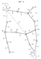
- Figure 3 is a view similar to Figure 1 showing illustrative modifications of the Figure 1 system in accordance with this invention.
- FIG. 1 An illustrative area 10 served by a communications system constructed in accordance with this invention is shown in FIG. 1.
- all of the communications links 50 in area 10 are assumed to be optical links.
- microwave links may be used in place of or in addition to optical links.
- Area 10 is accessed from two gateway locations or area access points 20a and 20b in or near area 10.
- Each of area access points 20 is connected to other external communications equipment (e.g., the global telephone network, one or more sources of television programming, etc.) via conventional connections 22.
- these connections 22 may be optical fibers extending to access points 20.
- Access points 20a and 20b are preferably substantially redundant of one another, offering substantially redundant communication with area 10. Therefore connections 22 are also preferably substantially redundant connections to the above-mentioned external communications equipment.
- Each of access points 20 preferably includes one or more (two in the depicted embodiment) free-space optical transceivers mounted relatively far from the ground to facilitate unobstructed, line-of-sight communication 50 between the access point transceivers and similar transceivers on nearby relay points (e.g., relay points 30a and 30f in the case of access point 20a, and relay points 30e and 30j in the case of access point 20b).
- the access point transceivers may be mounted on relatively tall structures such as high-rise apartment or office buildings, communications or electric utility towers, utility poles, or the like.
- the transceivers of relay points 30 (and end points 40, discussed below) may be mounted, for example, on the roofs of houses within area 10. Although longer distances may be used if desired, the typical distance between communicating points 20 and 30 is less than about 500 to about 1000 meters.
- Each relay point 30 has at least two, and in some cases more than two, free-space optical transceivers for line-of-sight optical communication 50 with an area access point 20, one or more other relay points 30, and/or one or more end points 40.
- relay point 30c is a typical relay point with two transceivers for optical communication 50 with relay points 30b and 30d, respectively.
- Relay point 30k is typical of a relay point with two transceivers for communicating with relay point 30g and end point 40a, respectively.
- relay point 30i is typical of a relay point with three transceivers for communicating with relay points 30d, 30h, and 30j, respectively.
- End points like 40a and 40b are similar to relay points 30, except that an end point has only one optical transceiver for free-space optical communication 50 with a relay point 30.
- each user of communications services in area 10 is associated with one of relay points 30 or end points 40.
- each relay point 30 or end point 40 generally has one or more users associated with it, although some relay points 30 without users may be needed to reach users at more distant relay or end points.
- Area 10 could be served from only one area access point 20, but it is preferred to have at least two area access points 20 for each area for such reasons as to provide backup in the event of failure or obstruction of one of the area access points or the optical communications links 50 between that area access point and the relay and/or end points in the area. More than two area access points 20 could be provided for area 10 to provide even more backup capability. Similarly, multiple links 50 from each access point 20 into area 10 are desirable for backup in the event of failure or obstruction of some links. At least some relay points 30 with three or more optical transceivers for communication 50 with three or more other relay points are also desirable to provide multiple communications paths through area 10 in the event of failure or obstruction of some links 50.
- relay point 30c can communicate via any of several paths such as 20a-30a-30b-30c, 20a-30f-30g-30h-30i-30d-30c, 20b-30e-30d-30c, and 20b-30j-30i-30d-30c. If the link 50 between relay points 30b and 30c were to fail or become obstructed, there would still be several paths via which full service could be maintained to relay point 30c.
- two free-space optical transceivers 120a and 120b and a radio antenna 130 are mounted on the roof of the house 110 of a user of the communications services provided by the system. At least one of transceivers 120 communicates bi-directionally via a free-space optical communication link 50 to an area access point 20 or another relay point 30. One of transceivers 120 may communicate with an end point 40. If the apparatus shown in FIG. 2 were for an end point 40, only one transceiver 120 would be required. In all other respects, the construction and operation of an end point 40 can be generally similar to what is shown in FIG. 2 and described below (with modifications appropriate to the presence of only one transceiver 120).
- Each transceiver 120 detects light it receives via the associated communication link 50 and produces a corresponding output signal applied to associated circuitry 150. Each transceiver 120 also responds to an input signal from circuitry 150 by transmitting corresponding light (e.g., from light emitting elements such as laser diodes) via the associated communication link 50.
- corresponding light e.g., from light emitting elements such as laser diodes
- Radio antenna 130 may be part of a conventional IS 136 radio port for cellular communication with other similar cellular communications equipment (e.g., at one or more of area access points 20 or other conventional cellular base stations). Any conventional cellular communication may be used such as CDMA, TDMA, IS95, or GSM. Radio antenna 130 may additionally be used for cellular communication with nearby wireless telephones such as the mobile cellular telephone shown at 140 in FIG. 2. In this context radio antenna 130 and associated circuitry 150 functions as a small base station.
- elements 120 and 130 are connected to relay point control circuitry 150.
- the user's communications equipment such as telephone 160, computer 170, and television 180 are also appropriately wired to control circuitry 150.
- Control circuitry 150 typically performs and/or controls several functions.
- One function of control circuitry 150 is to process signals from photodetectors in each of transceivers 120 and to cause the light emitting elements in the other of transceivers 120 to transmit corresponding light, possibly with some modifications.
- An example of such modifications is the addition to the light transmitted by transceivers 120 of information originating at relay point 30 (e.g., voice information from telephones 140 and/or 160, digital data information from computer 170, entertainment service request information from television equipment 180, etc.).
- the telephone voice information referred to in the preceding sentence includes other conventional telephone control information such on-hook, off-hook, dialing, cellular telephone identification and control information, etc.
- circuitry 150 Another function of circuitry 150 is to retrieve from the signals received via either of transceivers 120 information needed by the user at relay point 30. For example, circuitry 150 may extract from the received light voice information for use by telephones 140 and/or 160, digital data for use by computer 170, video information for use by television 180, etc.
- the above-mentioned telephone voice information includes other conventional telephone control information such as ringing, cellular telephone control information, etc.
- the above-mentioned video information may include television control information such as cable television "set top box" control information (e.g., viewer authorization codes, on-screen program guide data, etc.).
- circuitry 150 is to control reception and/or transmission of information via radio communications antenna 130.
- radio communication via antenna 130 may be used for such purposes as to turn on transceivers 120, to cause mechanisms associated with transceivers 120 to move those transceivers to look for the optical signal from other remote transceivers with which the first transceivers should establish links 50, etc.
- This type of radio communication may be cellular-type communication with a central location such as an area access point 20.
- Another example of the radio communications via antenna 130 that circuitry 150 may control is cellular communication with mobile cellular telephone 140 as described earlier.
- antenna 130 radio communication that circuitry 150 may control is cellular communication between relay point 30 and a central location such as an area access point 20 for the purpose of providing some basic backup service (such as basic telephone service) in the event all communication with relay point 30 via optical links 50 fails or is interrupted.
- a central location such as an area access point 20 for the purpose of providing some basic backup service (such as basic telephone service) in the event all communication with relay point 30 via optical links 50 fails or is interrupted.
- circuitry 150 may be to control normal automatic adjustments of the positions of transceivers 120 to maintain optimal optical communication 50 with other transceivers. For example, temperature or other environmental changes may cause a transceiver 120 to become misaligned with its intended optical communication path. This may be detected (e.g., by a quad sensor which is part of the transceiver) and the outputs of the detection applied to circuitry 150 for processing. The result of this processing may be output signals of circuitry 150 applied to mechanisms 122 that are capable of moving the misaligned transceiver. For example, mechanisms 122 may be capable of rotating the transceiver about vertical and horizontal axes, as well as shifting the transceiver left or right, or up or down.
- circuitry 150 forms part of servo controls for positioning or repositioning transceivers 120.
- This function of circuitry 150 is related to its possible use (described above) to initially position or reposition transceivers 120 during initial start-up, or during restarting or reconfiguring of the system after a failure or interruption.
- circuitry 150 may perform another function that circuitry 150 may perform is to select from among two or more received signals the better or best signal for use at relay point 30 and/or for retransmission to other points in the network (e.g., other relay points 30, end points 40, and/or area access points 20). For example, circuitry 150 may compare the strengths of the signals received via transceiver 120a and 120b. If circuitry 150 determines that the transceiver 120a signal is stronger and contains all the information needed by the user at relay point 30, circuitry 150 selects the transceiver 120a signal as the signal from which it derives the signals applied to devices 140, 160, 170, and/or 180.
- circuitry 150 determines that the transceiver 120b signal is stronger and contains all necessary information, circuitry 150 derives the signals for devices 140, 160, 170, and/or 180 from the transceiver 120b signal. If relay point 30 has three or more transducers 120, circuitry 150 may compare the strength and information content of all of the incoming signals and select the strongest and/or most complete signal for local use and retransmission via the other transceivers that were not the source of the selected signal.
- the communications links 50 in area 10 may carry the same or nearly the same information, while other links 50 may carry quite different information.
- the link 50 between relay points 30g and 30k will carry, in the direction from 30k to 30g, substantially only information originated by the users at relay point 30k and end point 40a. In the opposite direction this link 50 will tend to carry much more information.
- the links 50 between relay point 30g and relay points 30f and 30h will tend to carry, in both directions, the relatively large amounts of information launched from area access points 20a and 20b, as well as information added by users at relay point 30g and other points connected to point 30g by various routings through the network of links 50.
- circuitry 150 monitors the condition of the network at relay point 30 and to report that condition to overall network control circuitry 60 (see FIG. 1). Circuitry 150 transmits such reports using links 50 if possible; but if not, then via radio frequency antenna 130. For example, circuitry 150 may report that it is receiving signals via all of its transceivers 120, or it may report that one or more of its transceivers 120 is not receiving signals. As another example, circuitry 150 may report on the relative strengths of the transceiver 120 signals it is receiving.
- Overall network control circuitry 60 controls the flow of information throughout the network in area 10. To some extent circuitry 60 performs this function in cooperation with the circuitry 150 in each of the relay and end points 30 and 40 in area 10. For example, if one or more of circuits 150 reports to circuit 60 that a link 50 is not operating, circuit 60 attempts to find an alternate route for all information that would otherwise be carried by the inoperative link, and circuit 60 commands appropriate circuits 150 in a manner appropriate to establishing that altemate route.
- circuit 60 may instruct the circuit 150 at relay point 30b to direct all information originating at that relay point out via the link 50 to relay point 30a, and may similarly instruct the circuit 150 at relay point 30c to direct all information originating at that relay point out via the link 50 to relay point 30d.
- circuit 60 may instruct the circuitry 150 at relay point 30a to send information received from relay point 30b back to area access point 20a
- circuit 60 may instruct the circuitry 150 at relay point 30d to send information received from relay point 30c back to access point 20a or 20b via the best route (i.e., 30d-30i-30h-30g-30f-20a, 30d-30i-30j-20b, or 30d-30e-20b).
- the best route i.e., 30d-30i-30h-30g-30f-20a, 30d-30i-30j-20b, or 30d-30e-20b.
- Network control point circuit 60 may contain a database of the exact location of each transceiver 120. Such location information can be obtained at the time of installation using a global positioning system ("GPS") or differential GPS. Based on this information, circuit 60 can determine the pointing direction to instruct each transceiver 120 to use. For example, circuit 60 may direct the control circuitry 150 at relay point 30b to use the appropriate mechanism 122 to reposition its transceiver 120 that was previously pointed toward relay point 30c to point toward relay point 30i. Circuit 60 may do this by computing the exact angles both in the horizontal plane and elevation based on the locations of the transceivers. These locations are stored in a database and possibly are determined based on using GPS or a similar positioning system at the time of installation.
- GPS global positioning system
- circuit 60 may also direct the control circuit 150 at relay point 30i to use the appropriate mechanism 122 to reposition the transceiver 120 that was previously pointed toward relay point 30j to point toward relay point 30b. Once both transceivers are pointed in the correct direction, they may refine the alignment (again using mechanism 122) by going through a search pattern. Circuit 60 may also play a role in coordinating such a search process.
- control circuitry 60 cooperates with relay and end point control circuits 150 to control the routing of signals throughout area 10, both during normal operation of the system and when special measures must be taken to compensate for various kinds of failures or interruptions in the system.
- the manner in which responsibility for this control of the network is allocated between central control 60 and distributed controls 150 can be varied as desired. For example, virtually all of the signal routing control for the network can be allocated to central control 60, with distributed controls 150 primarily reporting local conditions and acting on instructions from the central control. Or more decision-making responsibility can be allocated to distributed controls 150 (e.g., decisions regarding which of two or more signals received via associated transceivers 120 should be retransmitted via the other transceivers associated with those controls).
- infrared light is used.
- One or several light frequencies may be used in each link 50.
- Information may be transmitted by analog or digital modulation of the light.
- the systems of this invention may employ many relatively short but interconnected free-space optical communications links 50 to reach users throughout potentially large areas.
- the optical signals are regenerated at each relay point 30 so that free-space optical communication can be used to enable information to travel relatively long distances.
- the network of free-space optical communications links 50 preferably has sufficient interconnectivity so that even if some links 50 fail or are interrupted, alternate routes can be found through the network to compensate for the failed or interrupted links. If all else fails, radio communication is available to maintain at least some service to any user.
- the radio frequency equipment at each relay and end point 30 and 40 doubles as base stations for local wireless telephone communication.
- FIG. 3 shows an alternative embodiment of the network of FIG. 1 in which bi-directional, line-of-sight, microwave communication links 70 are used as follows: (1) in place of the optical communication link 50 between nodes 20a and 30f, (2) as backup for the optical link 50 between nodes 30d and 30i, and (3) as another backup route into and out of area 10 between nodes 20a and 30i.
- microwave links 70 may be used as supplements or additions to optical links 50 or as replacements for optical links 50 in some instances.
- microwave links 70 may be useful for making longer connections than can conveniently be made optically.
- microwave links 70 may be useful for backing up particularly important optical links 50 in the event that bad weather interrupts those optical links.
- microwave links 70 may be generally similar to optical links 50.
- microwave links 120 can be converted to a microwave transceiver.
- one or more microwave transceivers can be added to the depicted optical transceivers 120.
- the relay point 30 apparatus can be constructed and operated as described above.
- Electric-magnetic communication is sometime used herein as a generic term for the above-described optical and microwave communication.
- the number of area access points 20 serving an area 10 can be more or less than the two shown in FIG. 1, the numbers of relay and end points 30 and 40 can be varied, the number of free-space, line-of-sight, electro-magnetic communication transceivers 120 at each relay point can be varied, etc.
- the use of end points 40 is entirely optional, and it may be possible to construct certain networks with only relay points 30 and no end points at all.
Landscapes
- Engineering & Computer Science (AREA)
- Computer Networks & Wireless Communication (AREA)
- Signal Processing (AREA)
- Mobile Radio Communication Systems (AREA)
- Radio Relay Systems (AREA)
- Small-Scale Networks (AREA)
- Optical Communication System (AREA)
- Telephonic Communication Services (AREA)
Applications Claiming Priority (2)
| Application Number | Priority Date | Filing Date | Title |
|---|---|---|---|
| US08/847,196 US6285857B1 (en) | 1997-05-01 | 1997-05-01 | Multi-hop telecommunications system and method |
| US847196 | 1997-05-01 |
Publications (2)
| Publication Number | Publication Date |
|---|---|
| EP0876006A2 true EP0876006A2 (de) | 1998-11-04 |
| EP0876006A3 EP0876006A3 (de) | 2000-01-26 |
Family
ID=25300037
Family Applications (1)
| Application Number | Title | Priority Date | Filing Date |
|---|---|---|---|
| EP98302379A Withdrawn EP0876006A3 (de) | 1997-05-01 | 1998-03-27 | Mehrsprung Telekommunikationsanordnung |
Country Status (5)
| Country | Link |
|---|---|
| US (2) | US6285857B1 (de) |
| EP (1) | EP0876006A3 (de) |
| JP (1) | JPH10341243A (de) |
| CN (1) | CN1242561C (de) |
| CA (1) | CA2229349C (de) |
Cited By (2)
| Publication number | Priority date | Publication date | Assignee | Title |
|---|---|---|---|---|
| EP1576824A1 (de) * | 2002-12-27 | 2005-09-21 | Avenir Numeric's | Digitales funk- und videodatenübertragungsgerät |
| US7813695B2 (en) | 2005-05-06 | 2010-10-12 | Telefonaktiebolaget L M Ericsson (Publ) | Mobile assisted relay selection in a telecommunications system |
Families Citing this family (28)
| Publication number | Priority date | Publication date | Assignee | Title |
|---|---|---|---|---|
| JP3364419B2 (ja) * | 1997-10-29 | 2003-01-08 | 新キャタピラー三菱株式会社 | 遠隔無線操縦システム並びに遠隔操縦装置,移動式中継局及び無線移動式作業機械 |
| US6363079B1 (en) * | 1997-12-31 | 2002-03-26 | At&T Corp. | Multifunction interface facility connecting wideband multiple access subscriber loops with various networks |
| US7184428B1 (en) * | 1997-12-31 | 2007-02-27 | At&T Corp. | Facility management platform for a hybrid coaxial/twisted pair local loop network service architecture |
| US20020051269A1 (en) * | 2000-09-29 | 2002-05-02 | Shlomo Margalit | Reconfigurable over-the-air optical data transmission system |
| JP2003044991A (ja) * | 2001-07-31 | 2003-02-14 | Toshiba Corp | 情報伝達システム、情報発信システム、車載情報端末 |
| RU2206959C2 (ru) * | 2001-09-12 | 2003-06-20 | Общество С Ограниченной Ответственностью "Сивера" | Способ и устройство передачи сообщения в мобильной системе связи |
| US7733904B1 (en) * | 2002-01-28 | 2010-06-08 | 3Com Corporation | System and method for roaming between wireless networks |
| KR100856045B1 (ko) * | 2002-04-11 | 2008-09-02 | 삼성전자주식회사 | 다중 홉 전달방법, 장치 및 그 방법에서 사용되는매체접근제어 데이터 자료구조 |
| CA2482185A1 (en) * | 2002-04-11 | 2003-10-16 | International Business Machines Corporation | Computer, computer security setting method, and program |
| US6842439B2 (en) | 2002-06-17 | 2005-01-11 | Harris Corporation | Free space optical terminal with ad hoc network back-up and associated methods |
| US7398097B2 (en) | 2002-12-23 | 2008-07-08 | Scott Technologies, Inc. | Dual-mesh network and communication system for emergency services personnel |
| US7263379B1 (en) | 2002-12-23 | 2007-08-28 | Sti Licensing Corp. | Communications network for emergency services personnel |
| US20040203666A1 (en) * | 2003-03-07 | 2004-10-14 | Foster Neal C. | System and method for aggregating network resources |
| NO20040110L (no) * | 2004-01-09 | 2005-07-11 | Geir Monsen Vavik | Signalrepeater system |
| US7400878B2 (en) * | 2004-02-26 | 2008-07-15 | Research In Motion Limited | Computing device with environment aware features |
| EP1760622B1 (de) * | 2004-02-26 | 2012-05-30 | Research In Motion Limited | Umgebungsbewusster Computer |
| US7983670B1 (en) * | 2004-03-18 | 2011-07-19 | Verizon Corporate Services Group Inc. | Wireless fallback for subscribers of wirelined networks |
| CN100450281C (zh) * | 2005-03-31 | 2009-01-07 | 西门子(中国)有限公司 | 一种分布式多跳无线网络的接入方法 |
| CN100428847C (zh) * | 2005-03-31 | 2008-10-22 | 西门子(中国)有限公司 | 一种集中式多跳无线网络的接入方法 |
| US7196930B2 (en) * | 2005-04-27 | 2007-03-27 | Micron Technology, Inc. | Flash memory programming to reduce program disturb |
| US20060276165A1 (en) * | 2005-06-01 | 2006-12-07 | Hidekazu Nakama | Dual mode communication system and method |
| US7652571B2 (en) | 2006-07-10 | 2010-01-26 | Scott Technologies, Inc. | Graphical user interface for emergency apparatus and method for operating same |
| GB2440982A (en) * | 2006-08-18 | 2008-02-20 | Fujitsu Ltd | Wireless multi-hop communication system |
| EP1937006A1 (de) * | 2006-12-22 | 2008-06-25 | Siemens Networks GmbH & Co. KG | Mehrfach-Antennen-Relaisstation mit Doppelkanal |
| JP2009005240A (ja) * | 2007-06-25 | 2009-01-08 | Nec Tokin Corp | 無線ネットワークシステムおよび無線ネットワーク通信方法 |
| KR100987219B1 (ko) * | 2007-06-29 | 2010-10-12 | 삼성전자주식회사 | 무선 통신 시스템에서 신호 송수신 방법 및 시스템 |
| JP5257477B2 (ja) * | 2011-03-07 | 2013-08-07 | 日本電気株式会社 | 光空間通信装置およびその通信方法ならびに光空間通信システム |
| JP6751520B2 (ja) * | 2015-10-13 | 2020-09-09 | ウシオ電機株式会社 | 光送受信装置及びこれを用いた光通信ネットワーク |
Family Cites Families (23)
| Publication number | Priority date | Publication date | Assignee | Title |
|---|---|---|---|---|
| US3824597A (en) * | 1970-11-09 | 1974-07-16 | Data Transmission Co | Data transmission network |
| US4284848A (en) * | 1979-08-01 | 1981-08-18 | Frost Edward G | Switched network telephone subscriber distribution system |
| US4578815A (en) | 1983-12-07 | 1986-03-25 | Motorola, Inc. | Wide area coverage radio communication system and method |
| US4682367A (en) * | 1985-11-13 | 1987-07-21 | General Electric Company | Mobile radio communications system with join feature |
| JPH01176127A (ja) * | 1987-12-28 | 1989-07-12 | Ncr Corp | 光空間通信システム |
| US4856046A (en) * | 1988-04-08 | 1989-08-08 | Jerry R. Iggulden | Remote public telephone link |
| US5301353A (en) * | 1990-02-12 | 1994-04-05 | Motorola, Inc. | Communication system and apparatus |
| US5241410A (en) * | 1990-06-21 | 1993-08-31 | Litephone Systems Ltd. | Enhanced infrared-connected telephone system |
| US5218715A (en) * | 1991-01-15 | 1993-06-08 | Orion Industries, Inc. | Multi-donor booster operation and system |
| JP2988742B2 (ja) | 1991-05-20 | 1999-12-13 | 株式会社東芝 | 無線通信装置の電界強度検出回路 |
| JPH0530000A (ja) * | 1991-07-18 | 1993-02-05 | Fujitsu Ltd | 移動体通信方式 |
| JPH0815267B2 (ja) | 1991-09-27 | 1996-02-14 | 松下電器産業株式会社 | 無線電話機 |
| CA2125411E (en) * | 1992-01-03 | 1996-06-25 | Andrew S. Beasley | Distributed rf repeater arrangement and method for linking wireless handsets to basestations |
| US5424859A (en) * | 1992-09-24 | 1995-06-13 | Nippon Telegraph And Telephone Corp. | Transceiver for wireless in-building communication sytem |
| JPH06315005A (ja) | 1993-04-30 | 1994-11-08 | Matsushita Electric Ind Co Ltd | 無線電話装置 |
| US5406615A (en) | 1993-08-04 | 1995-04-11 | At&T Corp. | Multi-band wireless radiotelephone operative in a plurality of air interface of differing wireless communications systems |
| GB9321657D0 (en) * | 1993-10-20 | 1993-12-08 | Ncr Int Inc | Power management system for a wireless network |
| US5400338A (en) * | 1994-02-08 | 1995-03-21 | Metricom, Inc. | Parasitic adoption of coordinate-based addressing by roaming node |
| AU2864995A (en) | 1994-06-17 | 1996-01-15 | Evelyn C. Price | Multilevel wireless communication system for hospitals |
| US5890055A (en) * | 1995-07-28 | 1999-03-30 | Lucent Technologies Inc. | Method and system for connecting cells and microcells in a wireless communications network |
| US6128512A (en) * | 1995-09-06 | 2000-10-03 | Cisco Systems, Inc. | Cellular communication system with dedicated repeater channels |
| US5737328A (en) * | 1995-10-04 | 1998-04-07 | Aironet Wireless Communications, Inc. | Network communication system with information rerouting capabilities |
| US5898679A (en) * | 1996-12-30 | 1999-04-27 | Lucent Technologies Inc. | Wireless relay with selective message repeat and method of operation thereof |
-
1997
- 1997-05-01 US US08/847,196 patent/US6285857B1/en not_active Expired - Lifetime
- 1997-12-31 US US09/001,363 patent/US20020068562A1/en not_active Abandoned
-
1998
- 1998-02-12 CA CA002229349A patent/CA2229349C/en not_active Expired - Fee Related
- 1998-03-27 EP EP98302379A patent/EP0876006A3/de not_active Withdrawn
- 1998-04-24 JP JP11402598A patent/JPH10341243A/ja active Pending
- 1998-04-29 CN CN98107474.XA patent/CN1242561C/zh not_active Expired - Fee Related
Cited By (2)
| Publication number | Priority date | Publication date | Assignee | Title |
|---|---|---|---|---|
| EP1576824A1 (de) * | 2002-12-27 | 2005-09-21 | Avenir Numeric's | Digitales funk- und videodatenübertragungsgerät |
| US7813695B2 (en) | 2005-05-06 | 2010-10-12 | Telefonaktiebolaget L M Ericsson (Publ) | Mobile assisted relay selection in a telecommunications system |
Also Published As
| Publication number | Publication date |
|---|---|
| CA2229349A1 (en) | 1998-11-01 |
| US6285857B1 (en) | 2001-09-04 |
| EP0876006A3 (de) | 2000-01-26 |
| CN1198619A (zh) | 1998-11-11 |
| CA2229349C (en) | 2002-04-02 |
| US20020068562A1 (en) | 2002-06-06 |
| JPH10341243A (ja) | 1998-12-22 |
| CN1242561C (zh) | 2006-02-15 |
Similar Documents
| Publication | Publication Date | Title |
|---|---|---|
| US6285857B1 (en) | Multi-hop telecommunications system and method | |
| US9426794B2 (en) | Wireless communication system and device for coupling a base station and mobile stations | |
| US6150987A (en) | Antenna assembly | |
| US6571284B1 (en) | Method for repeater management | |
| EP0664940B1 (de) | Rf zwischenstation fur duplex schnurlose telefonanordnung mit zeitmultiplex | |
| US7142847B2 (en) | Mobile communication system, resource switching method thereof, network control apparatus included therein, same and network control method | |
| US5371738A (en) | Wireless local area network system with mobile station handover | |
| EP1742429B1 (de) | Funknetzwerk, Relaisknotenpunkt, Kernknoten, geeignetes Relaisübertragungsverfahren und Programm dafür | |
| US20030216121A1 (en) | Method for in-building distribution using wireless access technology | |
| AU673755B2 (en) | Cordless telephone system and zone switching control method | |
| JP2002516050A (ja) | 自由空間光学リンクによって相互接続された小型無線セルを用いたハイブリッド汎用広帯域遠隔通信 | |
| AU656011B2 (en) | Base site with remote calibration capability | |
| US6580698B1 (en) | Path setting method in a mobile packet communication system | |
| EP1547412B1 (de) | Direkte zellulare kommunikation | |
| WO2000074281A1 (en) | System and method for line of sight path communication | |
| CA2019814A1 (en) | Dual donor booster system | |
| FI101331B (fi) | Tukiasema radiopuhelinliikennejärjestelmää varten | |
| HK1015093A (en) | Multi-hop telecommunications system | |
| MXPA98003298A (es) | Sistemas de telecomunicaciones de multiple salto | |
| US20050032545A1 (en) | Fixed wireless back haul for mobile communications using stratospheric platforms | |
| JP2007295349A (ja) | 通信中継システム及び通信中継方法 | |
| EP1240792B1 (de) | Verfahren und anordnung zur redundanzeinrichtung für ein funkkommunikationessystem | |
| JP3929193B2 (ja) | 光無線通信システムおよび光無線通信方法 | |
| CN105407320B (zh) | 一种无线视频监控节点以及自愈方法 | |
| JPH04142820A (ja) | 移動通信における基地局送信方式 |
Legal Events
| Date | Code | Title | Description |
|---|---|---|---|
| PUAI | Public reference made under article 153(3) epc to a published international application that has entered the european phase |
Free format text: ORIGINAL CODE: 0009012 |
|
| AK | Designated contracting states |
Kind code of ref document: A2 Designated state(s): DE FR GB |
|
| AX | Request for extension of the european patent |
Free format text: AL;LT;LV;MK;RO;SI |
|
| PUAL | Search report despatched |
Free format text: ORIGINAL CODE: 0009013 |
|
| RIC1 | Information provided on ipc code assigned before grant |
Free format text: 7H 04B 7/155 A, 7H 04Q 7/20 B |
|
| AK | Designated contracting states |
Kind code of ref document: A3 Designated state(s): AT BE CH DE DK ES FI FR GB GR IE IT LI LU MC NL PT SE |
|
| AX | Request for extension of the european patent |
Free format text: AL;LT;LV;MK;RO;SI |
|
| 17P | Request for examination filed |
Effective date: 20000216 |
|
| AKX | Designation fees paid |
Free format text: DE FR GB |
|
| STAA | Information on the status of an ep patent application or granted ep patent |
Free format text: STATUS: THE APPLICATION IS DEEMED TO BE WITHDRAWN |
|
| 18D | Application deemed to be withdrawn |
Effective date: 20031001 |
|
| REG | Reference to a national code |
Ref country code: HK Ref legal event code: WD Ref document number: 1015093 Country of ref document: HK |