EP0876090A2 - Gehäuse mit Wandungen und wenigstens einer Öffnung darin - Google Patents
Gehäuse mit Wandungen und wenigstens einer Öffnung darin Download PDFInfo
- Publication number
- EP0876090A2 EP0876090A2 EP98104444A EP98104444A EP0876090A2 EP 0876090 A2 EP0876090 A2 EP 0876090A2 EP 98104444 A EP98104444 A EP 98104444A EP 98104444 A EP98104444 A EP 98104444A EP 0876090 A2 EP0876090 A2 EP 0876090A2
- Authority
- EP
- European Patent Office
- Prior art keywords
- housing according
- profiles
- engagement
- profile
- shielding
- Prior art date
- Legal status (The legal status is an assumption and is not a legal conclusion. Google has not performed a legal analysis and makes no representation as to the accuracy of the status listed.)
- Granted
Links
Images

Classifications
-
- E—FIXED CONSTRUCTIONS
- E06—DOORS, WINDOWS, SHUTTERS, OR ROLLER BLINDS IN GENERAL; LADDERS
- E06B—FIXED OR MOVABLE CLOSURES FOR OPENINGS IN BUILDINGS, VEHICLES, FENCES OR LIKE ENCLOSURES IN GENERAL, e.g. DOORS, WINDOWS, BLINDS, GATES
- E06B5/00—Doors, windows, or like closures for special purposes; Border constructions therefor
- E06B5/10—Doors, windows, or like closures for special purposes; Border constructions therefor for protection against air-raid or other war-like action; for other protective purposes
- E06B5/18—Doors, windows, or like closures for special purposes; Border constructions therefor for protection against air-raid or other war-like action; for other protective purposes against harmful radiation
-
- H—ELECTRICITY
- H05—ELECTRIC TECHNIQUES NOT OTHERWISE PROVIDED FOR
- H05K—PRINTED CIRCUITS; CASINGS OR CONSTRUCTIONAL DETAILS OF ELECTRIC APPARATUS; MANUFACTURE OF ASSEMBLAGES OF ELECTRICAL COMPONENTS
- H05K9/00—Screening of apparatus or components against electric or magnetic fields
- H05K9/0007—Casings
- H05K9/0015—Gaskets or seals
Definitions
- the invention relates to a housing with walls and with at least an opening in it that is covered by a cover, e.g. B. in the form of a door or window, closable is, cover and opening surrounded by frame profiles which are overlapping areas and which are a shielding device for shielding between the frame profiles against high-frequency waves and impulses.
- a cover e.g. B. in the form of a door or window, closable is, cover and opening surrounded by frame profiles which are overlapping areas and which are a shielding device for shielding between the frame profiles against high-frequency waves and impulses.
- EMI electromagnetic interference
- EMP electromagnetic Pulses
- NELP nuclear electromagnetic pulses
- the engagement profiles can be of any design as long as there are contact surfaces, that of power transmission to serve. Wedge profiles have proven particularly effective, since this creates a play-free contact surface is achievable.
- the engagement profiles should preferably be used be designed such that at least result in three adjacent contact surface pairs.
- a surprising effect is that the contact surfaces at the same time also good shielding against high-frequency Form waves and impulses, with the contact surfaces as possible uninterrupted over the entire scope of the frame profiles should go.
- the high frequency seal can still be improved if the contact surfaces have a tin coating receive.
- the engagement profiles at least one longitudinal groove have, in each of which a shielding element is used is.
- the or one of the longitudinal grooves can be in a contact surface be molded.
- a possible embodiment consists of inserting a coil spring into the longitudinal groove, which in the closed state of the cover on the each lies opposite contact surface.
- the Coil spring can be wound from flat wire.
- a support core can be provided.
- the number of longitudinal grooves can correspond to the respective Conditions can be selected. With just two longitudinal grooves and shielding elements arranged therein can provide good shielding against high-frequency waves and impulses.
- a longitudinal groove is provided in at least one profile base of the engagement profile (s) .
- This longitudinal groove (s) offers space to remove any contamination in these to be able to displace. If possible, in each A longitudinal groove must be formed in the base of the profile. In addition can also use this longitudinal groove (s) for the arrangement of shielding elements be used, for example in the form of a Sealing cord made of metallic mesh fabric.
- an environmental seal is arranged in the overlap area is.
- it can have a plastic strand, who sits in a groove in the one frame profile and against which a frame web of the other frame profile is pressed is.
- the plastic strand should have a metal insert.
- the Plastic strand in the groove base to be supported over ribs.
- one of the frame profiles is designed as a hollow profile, which on the the side facing away from the engagement profiles with a wall section forms a second overlap area, wherein Hollow profile and wall section in this area Fasteners forming contact surfaces with one another are connected.
- the hollow profile and wall section should be used two engagement profiles with the formation of Form contact areas. This can be achieved that the hollow profile-side engagement profiling from grooves are formed with contact surfaces on the groove outlets, in surround the engaging webs molded into the wall section.
- the frame profiles facing away from the engagement profiles Form another overlap area and lie there against one another via at least one further shielding element. This will also on the other side of the Electromagnetic shielding causes housing supports the shielding due to the engagement profiles.
- the shielding elements not just designed as coil springs are, but at least partially as longitudinal leaf springs.
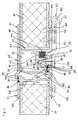
- the section according to FIG. 1 is reduced to a wall side Frame profile 1 and a door-side frame profile 2.
- Both frame profiles 1, 2 are via a conventional door hinge connected to each other, for the sake of clarity is omitted.
- Both frame profiles 1, 2 are extruded Aluminum profiles.
- the wall-side frame profile 1 is formed in two parts. It has a hollow profile body 3, in the interior of which 4 corner profiles can be inserted at the top and bottom. Of the Hollow profile body 3 has a transverse wall 5 on the wall, which extends up to goes to the outside and there at right angles in a binding leg 6 expires.
- the inside of the hollow profile body 3 is an inner profile 7 covered, the wall also in one Binding leg 8 runs out, which is parallel to the other binding leg 6 runs. Both border legs 6, 8 lie with their insides on the outside of the not shown here Wall element on, so grasp this in the area of Front side and are firmly connected to the wall element.
- the hollow profile body 3 has two longitudinal grooves 9, 10, in enclose the longitudinal webs 11, 12, which of the inner profile 7 project.
- the longitudinal grooves 9, 10 point in the respective groove outlet area Bevels on that with complementary bevels correspond on the longitudinal webs 11, 12 in such a way that a total of four contact surface pairs 13, 14, 15, 16 be formed.
- the contact surface pairs 13, 14, 15, 16 lie biased against each other, since the inner profile 7 the hollow profile body 3 with a plurality of rivets connected is.
- the door-side frame profile 2 has a transverse wall 17 with inside and outside profiling for the use of Locking elements or the like. From the outside of the bulkhead 17 go out parallel Einfrawschenkel 18, 19, the Border the end face area of a door leaf serve. The inside of them are under tension on the outside of the door leaf when both are connected.
- the door-side frame profile 2 sits in one Overlap web 20 continues, which with the hollow profile body 3 overlaps.
- the overlap web 20 runs in one the hollow profile body 3 directed sealing strip 21.
- This Sealing strip 21 engages in a rubber-elastic plastic strand 22 a, which forms an environmental seal and in addition
- Metal inserts 23 contains a supplementary electromagnetic To achieve shielding.
- the plastic strand 22 sits in a vertical longitudinal groove 24 which is from the transverse wall 5 and the hollow profile body 3 is formed. On the back the plastic strand 22 is supported by two ribs 25, 26 from, which promote the flexibility of the plastic strand 22.
- Both the hollow profile body 3 and the overlap web 20 have engagement profiles on their opposite sides 27, 28 that complement each other are trained.
- the engagement profile 27 consists of a V-rib 29 and a projection 30, wherein the V-rib 29 and projection 30 include a V-shaped groove.
- This Opposite is a complementary V-rib 31 of the engagement profile 28.
- the intervention profiling 28 a bevel 32.
- This and the V-rib 31 close a groove in which the V-rib 29 surrounds complementary.
- the contact surface pairs 33, 34, 35 are with pewter to provide the best possible electrical To make contact.
- Each in the groove base of the grooves of both engagement profiles 27, 28 are approximately semicircular recesses 36, 37 formed. First and foremost, they form displacement space for eventuals Pollution. However, they can also be used shielding elements, for example copper mesh fabrics and tin are used to shield the electromagnetic to improve even further.
- FIG. 2 also shows a frame profile 51 on the wall and a door-side frame profile 52 is shown. Both frame profiles 51, 52 are 53 via a conventional door hinge connected, the first hinge leaf 54 with the wall side Frame profile 51 via screws 55, 56 and its second Hinge leaf 57 via screws 58, 59 with the door side Frame profile 52 are firmly connected.
- a hinge joint 60 connects both hinge leaves 54, 57.
- the wall-side frame profile 51 is formed in two parts. It has a hollow profile body 61, in the interior of which 62 corner profiles can be used on the top and bottom. Of the Hollow profile body 61 has a transverse wall 63 on the wall, which up to goes to the outside and there at right angles in a binding leg 64 passes.
- the hollow profile body 61 is sealed by a Inner profile 65 covered, also in a border leg 66 runs out, which is parallel to the other border leg 64 extends. Both border legs 64, 66 are about their insides on the outside of a wall element 67 attached, which is designed as a conventional sandwich plate is.
- the door-side frame profile 52 has a transverse wall 68.
- Parallel binding legs extend from the outer sides of the transverse wall 68 69, 70 from the front area of a door leaf Border 71.
- the door leaf 71 also consists of a usual sandwich plate.
- Door leaf 71 and frame leg 69, 70 are firmly connected.
- the door-side sits on the outside of the housing Frame profile 52 continues in an overlap web 72, which overlapped with the hollow profile body 61.
- the overlap 72 runs in a direction of the hollow profile body 61 Sealing strip 73. It fits into a rubber elastic Plastic strand 74, which forms an environmental seal. He can as in the embodiment of Figure 1 additional Metal inserts contain a complementary electromagnetic To achieve shielding.
- the plastic strand 74 sits in a vertical longitudinal groove 75 which is from the transverse wall 63 and the hollow profile body 61 is formed. On the back is the longitudinal groove 75 curved to the flexibility of the To promote plastic strand 74.
- Both the hollow profile body 61 and the overlap web 72 have engagement profiles on their opposite sides 76, 77, which are complementary to each other are trained.
- the engagement profile 76 consists of a V-rib 78 and a projection 79, wherein the V-rib 78 and projection 79 include a V-shaped groove.
- This A complementary V-rib 80 is located opposite the groove the engagement profiling 77.
- the engagement profiling 77 a V-shaped groove 81 into which the V-rib 78 complements. Doing so in the closed state of the door leaf 71 four contact surface pairs 82, 83, 84, 85 are formed, over which the engagement profiles 76, 77 to each other issue.
- the groove in which the V-rib 78 surrounds a slightly more than semicircular recess 87 is formed is formed.
- the V-rib 78 surrounds a slightly more than semicircular recess 87 is formed.
- it primarily forms displacement space for possible soiling.
- a mesh shielding fabric made of copper and tin provided the electromagnetic shielding even further to improve.
- the slope of the V-rib 80 which lies opposite the V-rib 78, is a flat groove, in which a shield spring 88 used and held there positively is.
- the shielding spring 88 is made of a copper-beryllium-tin alloy and has a protruding from the groove Spring leg 89 on. He is in the drawing shown unstressed state. In fact, he will deformed by the V-rib 78 and is therefore due to it also with preload.
- a safety wire 90 ensures that the shield spring 88 does not fall out of the groove can.
- V-rib 78 On the other side of the V-rib 78 is one similar shielding spring 91. It is with a longitudinal edge in the transverse wall 68 and with the other edge in the overlap web 72 held there and also with the help of a safety wire 92 secured. Your spring leg 93 is also drawn undisturbed. In fact, it is through the V-rib 78 deformed when the door leaf 71 is closed, see above that it bears against the V-rib 78 with prestress. Both Shielding springs 88, 91 form further electromagnetic shielding elements.
- Another shielding spring 94 is inserted into a groove 95, which is molded into the inside leg 70 is. This shielding spring 94 is also by a safety wire 96 secured against falling out. On the shield spring 94 there is a continuation 97 of the binding leg 66, so that it too is compressed slightly. This gives another shield.
Landscapes
- Engineering & Computer Science (AREA)
- Health & Medical Sciences (AREA)
- Toxicology (AREA)
- Civil Engineering (AREA)
- Structural Engineering (AREA)
- Microelectronics & Electronic Packaging (AREA)
- Shielding Devices Or Components To Electric Or Magnetic Fields (AREA)
- External Artificial Organs (AREA)
- Casings For Electric Apparatus (AREA)
- Refrigerator Housings (AREA)
Abstract
Description
- Figur 1
- einen Horizontalschnitt mit Rahmenprofilen, die zur Wandung eines Gehäuses gehören und
- Figur 2
- einen Horizontalschnitt mit einer zweiten Version von Rahmenprofilen, die zur Wandung eines Gehäuses gehören.
Claims (23)
- Gehäuse mit Wandungen (67) und mit wenigstens einer Öffnung darin, die mittels einer Abdeckung, z. B. in Form einer Tür (71) oder eines Fensters, verschließbar ist, wobei Abdeckung (71) und Öffnung von Rahmenprofilen (1, 2; 51, 52) umgeben sind, welche Überlappungsbereiche bilden und die eine Abschirmeinrichtung zur Abschirmung zwischen den Rahmenprofilen (1, 2; 51, 52) gegen hochfrequente Wellen und Impulse aufweisen, dadurch gekennzeichnet, daß die Überlappungsbereiche an den einander zugewandten Seiten komplementäre Eingriffsprofilierungen (27, 28; 76, 77) aufweisen, welche unter Ausbildung von Kontaktflächen (33, 34, 35; 82, 83, 84, 85) formschlüssig ineinanderfassen.
- Gehäuse nach Anspruch 1, dadurch gekennzeichnet, daß die Eingriffsprofilierungen (27, 28; 76, 77) als Keilprofilierungen (29, 31; 78, 80) ausgebildet sind.
- Gehäuse nach Anspruch 1 oder 2, dadurch gekennzeichnet, daß die Eingriffsprofilierungen (27, 28; 76, 77) derart ausgebildet sind, daß sich zumindest drei aneinanderliegende Kontaktflächenpaare (33, 34, 35; 82, 83, 84, 85) ergeben.
- Gehäuse nach einem der Ansprüche 1 bis 3, dadurch gekennzeichnet, daß die Kontaktflächen (33, 34, 35; 82, 83, 84, 85) einen Zinnbelag aufweisen.
- Gehäuse nach einem der Ansprüche 1 bis 4, dadurch gekennzeichnet, daß wenigstens eine der Eingriffsprofilierungen (27, 28; 77) wenigstens eine Längsnut (38, 39) aufweisen, in die jeweils ein Abschirmelement (40, 41; 88, 91) eingesetzt ist.
- Gehäuse nach Anspruch 5, dadurch gekennzeichnet, daß die bzw. wenigstens eine der Längsnuten (38, 39) in eine Kontaktfläche (33, 35; 84) eingeformt ist.
- Gehäuse nach Anspruch 6, dadurch gekennzeichnet, daß in die Längsnut(en) jeweils eine Schraubenfeder (40, 41) als Abschirmelement eingesetzt ist, welche in geschlossenem Zustand der Abdeckung an der jeweils gegenüberliegenden Kontaktfläche anliegt.
- Gehäuse nach Anspruch 7, dadurch gekennzeichnet, daß die Schraubenfeder (40, 41) aus Flachdraht besteht.
- Gehäuse nach Anspruch 7 oder 8, dadurch gekennzeichnet, daß die Schraubenfeder(n) (40, 41) einen Stützkern aufweist.
- Gehäuse nach einem der Ansprüche 6 bis 9, dadurch gekennzeichnet, daß zwei Längsnuten (38, 39) vorgesehen sind.
- Gehäuse nach einem der Ansprüche 1 bis 10, dadurch gekennzeichnet, daß in wenigstens einem Profilgrund der Eingriffsprofilierung(en) (27, 28) eine Längsnut (36, 37; 87) vorgesehen ist.
- Gehäuse nach Anspruch 11, dadurch gekennzeichnet, daß Längsnuten (36, 37) in jedem Profilgrund eingeformt sind.
- Gehäuse nach Anspruch 11 oder 12, dadurch gekennzeichnet, daß in die Längsnut(en) jeweils ein Abschirmelement eingesetzt ist.
- Gehäuse nach Anspruch 13, dadurch gekennzeichnet, daß in die Längsnut(en) (36, 37) eine Dichtschnur, z. B. ein metallisches Mesh-Gewebe mit Stützkern, eingesetzt ist bzw. sind.
- Gehäuse nach einem der Ansprche 1 bis 14, dadurch gekennzeichnet, daß im Überlappungsbereich eine Umweltdichtung (21, 22; 74) angeordnet ist.
- Gehäuse nach Anspruch 15, dadurch gekennzeichnet, daß die Umweltdichtung einen Kunststoffstrang (22; 74) aufweist, der in einer Nut (24; 75) in dem einen Rahmenprofil (1) sitzt und gegen die ein Rahmensteg (21; 72) des anderen Rahmenprofils (2; 52) gepreßt ist.
- Gehäuse nach Anspruch 16, dadurch gekennzeichnet, daß der Kunststoffstrang (22; 74) eine Metalleinlage (23) aufweist.
- Gehäuse nach Anspruch 16 oder 17, dadurch gekennzeichnet, daß der Kunststoffstrang (22) im Nutgrund über Rippen (25, 26) abgestützt ist.
- Gehäuse nach einem der Ansprüche 1 bis 18, dadurch gekennzeichnet, daß eines der Rahmenprofile (1) als Hohlprofil (3) ausgebildet ist, welches an der den Eingriffsprofilierungen (27, 28) abgewandten Seite mit einem Wandungsabschnitt (7) einen weiteren Überlappungsbereich bildet, wobei Hohlprofil (3) und Wandungsabschnitt (7) in diesem Bereich über Befestigungsmittel unter Bildung von Kontaktflächen (13, 14, 15, 16) miteinander verbunden sind.
- Gehäuse nach Anspruch 19, dadurch gekennzeichnet, daß Hohlprofil (3) und Wandungsabschnitt (7) zweite Eingriffsprofilierungen unter Ausbildung der Kontaktflächen (13, 14, 15, 16) bilden.
- Gehäuse nach Anspruch 20, dadurch gekennzeichnet, daß die hohlprofilseitige Eingriffsprofilierung aus Nuten (9, 10) mit Kontaktflächen an den Nutausläufen ausgebildet sind, in die wandabschnittseitig eingeformte Eingriffsstege (11, 12) einfassen.
- Gehäuse nach einem der Ansprüche 1 bis 21, dadurch gekennzeichnet, daß die Rahmenprofile (51, 52) an der den Eingriffsprofilierungen (76, 77) abgewandten Seite einen weiteren Überlappungsbereich bilden und dort über wenigstens ein weiteres Abschirmelement (94) aneinanderliegen.
- Gehäuse nach einem der Ansprüche 1 bis 22, dadurch gekennzeichnet, daß die Abschirmelemente teilweise als Längsblattfedern (88, 91, 94) ausgebildet sind.
Priority Applications (1)
| Application Number | Priority Date | Filing Date | Title |
|---|---|---|---|
| SI9830369T SI0876090T1 (en) | 1997-03-14 | 1998-03-12 | Housing with walls and at least one opening in them |
Applications Claiming Priority (2)
| Application Number | Priority Date | Filing Date | Title |
|---|---|---|---|
| DE29704674U DE29704674U1 (de) | 1997-03-14 | 1997-03-14 | Gehäuse mit Wandungen und wenigstens einer Öffnung darin |
| DE29704674U | 1997-03-14 |
Publications (3)
| Publication Number | Publication Date |
|---|---|
| EP0876090A2 true EP0876090A2 (de) | 1998-11-04 |
| EP0876090A3 EP0876090A3 (de) | 1999-11-24 |
| EP0876090B1 EP0876090B1 (de) | 2003-02-26 |
Family
ID=8037495
Family Applications (1)
| Application Number | Title | Priority Date | Filing Date |
|---|---|---|---|
| EP98104444A Expired - Lifetime EP0876090B1 (de) | 1997-03-14 | 1998-03-12 | Gehäuse mit Wandungen und wenigstens einer Öffnung darin |
Country Status (4)
| Country | Link |
|---|---|
| EP (1) | EP0876090B1 (de) |
| AT (1) | ATE233467T1 (de) |
| DE (2) | DE29704674U1 (de) |
| SI (1) | SI0876090T1 (de) |
Cited By (1)
| Publication number | Priority date | Publication date | Assignee | Title |
|---|---|---|---|---|
| EP1050488A2 (de) | 1999-05-05 | 2000-11-08 | M. Schall GmbH + Co. KG | Containergruppe sowie Verfahren zum Verbinden der Container |
Families Citing this family (2)
| Publication number | Priority date | Publication date | Assignee | Title |
|---|---|---|---|---|
| CN102561910A (zh) * | 2012-02-22 | 2012-07-11 | 宜兴市万向防火门有限公司 | 一种核电防辐射门 |
| RU210567U1 (ru) * | 2021-12-27 | 2022-04-21 | Вячеслав Владимирович Вяткин | Дверь камеры налива аквавендингового аппарата |
Family Cites Families (9)
| Publication number | Priority date | Publication date | Assignee | Title |
|---|---|---|---|---|
| DE1982467U (de) * | 1967-11-02 | 1968-04-04 | Telefunken Patent | Anordnung zur herstellung zahlreicher leitender verbindungen zwischen zwei gegeneinander beweglichen elektrischen leitern grosser oberflaeche. |
| DE2605257A1 (de) * | 1976-02-11 | 1977-08-18 | Continental Gummi Werke Ag | Streifen- oder schnurfoermige dichtung fuer elektrische, elektronische oder funkgeraete und deren bauteile |
| GB2194814B (en) * | 1986-08-30 | 1990-05-16 | Marconi Co Ltd | A door seal for excluding electromagnetic interference |
| GB2194683B (en) * | 1986-08-30 | 1990-03-21 | Marconi Co Ltd | A technique for connecting frame and panel members to produce an rf seal |
| DE3640817A1 (de) * | 1986-11-28 | 1988-06-30 | Juergen Dipl Ing Bergerhoff | Abgeschirmtes gehaeuse |
| DE8716599U1 (de) * | 1987-12-16 | 1988-03-31 | Zeppelin-Metallwerke Gmbh, 7990 Friedrichshafen | Elektromagnetisch abgeschirmte Kabine mit einem Dichtungssystem |
| DE9013936U1 (de) * | 1990-10-06 | 1990-12-06 | Hirono, Kohji, Nagoya, Aichi | Dichtungsmaterial zur Abschirmung elektromagnetischer Wellen |
| DE4105933A1 (de) * | 1991-02-26 | 1992-08-27 | Becker Walter Gmbh | Mit einer tuer oder einem deckel zu verschliessende oeffnung eines gehaeuses |
| DE9318353U1 (de) * | 1993-12-01 | 1994-06-09 | M. Schall Gmbh + Co Kg, 52399 Merzenich | Abdichteinrichtung gegen hochfrequente Wellen oder Impulse |
-
1997
- 1997-03-14 DE DE29704674U patent/DE29704674U1/de not_active Expired - Lifetime
-
1998
- 1998-03-12 AT AT98104444T patent/ATE233467T1/de active
- 1998-03-12 EP EP98104444A patent/EP0876090B1/de not_active Expired - Lifetime
- 1998-03-12 SI SI9830369T patent/SI0876090T1/xx unknown
- 1998-03-12 DE DE59807272T patent/DE59807272D1/de not_active Expired - Lifetime
Cited By (2)
| Publication number | Priority date | Publication date | Assignee | Title |
|---|---|---|---|---|
| EP1050488A2 (de) | 1999-05-05 | 2000-11-08 | M. Schall GmbH + Co. KG | Containergruppe sowie Verfahren zum Verbinden der Container |
| EP1050488A3 (de) * | 1999-05-05 | 2002-11-27 | M. Schall GmbH + Co. KG | Containergruppe sowie Verfahren zum Verbinden der Container |
Also Published As
| Publication number | Publication date |
|---|---|
| SI0876090T1 (en) | 2003-08-31 |
| ATE233467T1 (de) | 2003-03-15 |
| DE29704674U1 (de) | 1997-05-15 |
| EP0876090B1 (de) | 2003-02-26 |
| DE59807272D1 (de) | 2003-04-03 |
| EP0876090A3 (de) | 1999-11-24 |
Similar Documents
| Publication | Publication Date | Title |
|---|---|---|
| EP0528240B1 (de) | Geräteschrank | |
| EP0134540B1 (de) | Hochfrequenzdichte Abschirmung von Flächenteilen | |
| EP0789983A1 (de) | Rahmenschenkel für ein rahmengestell eines schaltschrankes | |
| EP0528239B1 (de) | Geräteschrank | |
| DE4311246C1 (de) | Gehäuse für elektronische Geräte | |
| EP0200054B1 (de) | Kontaktvorrichtung für geschirmte Kabinen und Räume mit HF-dicht geschirmten, gegeneinander beweglichen Gehäuseteilen | |
| EP1775413B1 (de) | Pneumatische Dichtung für Türen oder Tore sowie Tür oder Tor mit einer solchen Dichtung zum Schutz gegen elektromagnetische Impulse | |
| EP0650317B1 (de) | Baugruppenträger | |
| EP2400209A2 (de) | Lichtband | |
| DE69911383T2 (de) | Durchführungseinrichtung | |
| EP0681081A1 (de) | Abschlusselement für Wandöffnungen in Gebäuden od. dgl. | |
| DE4233785A1 (de) | Durchfuehrungs- und erdungsstueck fuer kabel | |
| EP0876090A2 (de) | Gehäuse mit Wandungen und wenigstens einer Öffnung darin | |
| EP0269126B1 (de) | Abgeschirmtes Gehäuse | |
| DE19646481C2 (de) | Gehäuse für elektrische Komponenten und Baugruppen | |
| DE3204274C2 (de) | Türanordnung für einen elektromagnetisch abgeschirmten Raum | |
| DE9103080U1 (de) | Abgeschirmtes Gehäuse für elektrische Geräte | |
| DE1914083A1 (de) | Trennbare Abschirmeinrichtung an Maschinenverkleidungen | |
| EP1050488A2 (de) | Containergruppe sowie Verfahren zum Verbinden der Container | |
| DE10328402B4 (de) | Schaltschrank | |
| DE20204910U1 (de) | Schrank | |
| DE2348910C3 (de) | Hochfrequenztechnische Geräteanordnung | |
| DE69023901T2 (de) | Wellenabschirmmittel für Mikrowellenofen. | |
| DE9305233U1 (de) | Gehäuse für elektronische Geräte | |
| DE9110261U1 (de) | Geräteschrank |
Legal Events
| Date | Code | Title | Description |
|---|---|---|---|
| PUAI | Public reference made under article 153(3) epc to a published international application that has entered the european phase |
Free format text: ORIGINAL CODE: 0009012 |
|
| AK | Designated contracting states |
Kind code of ref document: A2 Designated state(s): AT BE CH DE FR GB LI NL SE |
|
| AX | Request for extension of the european patent |
Free format text: AL;LT;LV;MK;RO;SI |
|
| PUAL | Search report despatched |
Free format text: ORIGINAL CODE: 0009013 |
|
| AK | Designated contracting states |
Kind code of ref document: A3 Designated state(s): AT BE CH DE DK ES FI FR GB GR IE IT LI LU MC NL PT SE |
|
| AX | Request for extension of the european patent |
Free format text: AL;LT;LV;MK;RO;SI |
|
| 17P | Request for examination filed |
Effective date: 19991220 |
|
| AKX | Designation fees paid |
Free format text: AT BE CH DE FR GB LI NL SE |
|
| AXX | Extension fees paid |
Free format text: SI PAYMENT 19991220 |
|
| 17Q | First examination report despatched |
Effective date: 20010130 |
|
| GRAH | Despatch of communication of intention to grant a patent |
Free format text: ORIGINAL CODE: EPIDOS IGRA |
|
| GRAH | Despatch of communication of intention to grant a patent |
Free format text: ORIGINAL CODE: EPIDOS IGRA |
|
| GRAA | (expected) grant |
Free format text: ORIGINAL CODE: 0009210 |
|
| AK | Designated contracting states |
Designated state(s): AT BE CH DE FR GB LI NL SE |
|
| AX | Request for extension of the european patent |
Extension state: SI |
|
| REG | Reference to a national code |
Ref country code: GB Ref legal event code: FG4D Free format text: NOT ENGLISH |
|
| REG | Reference to a national code |
Ref country code: CH Ref legal event code: EP |
|
| REF | Corresponds to: |
Ref document number: 59807272 Country of ref document: DE Date of ref document: 20030403 Kind code of ref document: P |
|
| GBT | Gb: translation of ep patent filed (gb section 77(6)(a)/1977) |
Effective date: 20030520 |
|
| ET | Fr: translation filed | ||
| PLBE | No opposition filed within time limit |
Free format text: ORIGINAL CODE: 0009261 |
|
| STAA | Information on the status of an ep patent application or granted ep patent |
Free format text: STATUS: NO OPPOSITION FILED WITHIN TIME LIMIT |
|
| 26N | No opposition filed |
Effective date: 20031127 |
|
| REG | Reference to a national code |
Ref country code: SI Ref legal event code: IF |
|
| REG | Reference to a national code |
Ref country code: FR Ref legal event code: PLFP Year of fee payment: 19 |
|
| REG | Reference to a national code |
Ref country code: FR Ref legal event code: PLFP Year of fee payment: 20 |
|
| PGFP | Annual fee paid to national office [announced via postgrant information from national office to epo] |
Ref country code: FR Payment date: 20170224 Year of fee payment: 20 Ref country code: CH Payment date: 20170327 Year of fee payment: 20 Ref country code: DE Payment date: 20170225 Year of fee payment: 20 Ref country code: NL Payment date: 20170316 Year of fee payment: 20 Ref country code: SE Payment date: 20170327 Year of fee payment: 20 |
|
| PGFP | Annual fee paid to national office [announced via postgrant information from national office to epo] |
Ref country code: AT Payment date: 20170316 Year of fee payment: 20 Ref country code: GB Payment date: 20170327 Year of fee payment: 20 Ref country code: BE Payment date: 20170227 Year of fee payment: 20 |
|
| REG | Reference to a national code |
Ref country code: DE Ref legal event code: R071 Ref document number: 59807272 Country of ref document: DE |
|
| REG | Reference to a national code |
Ref country code: NL Ref legal event code: MK Effective date: 20180311 |
|
| REG | Reference to a national code |
Ref country code: BE Ref legal event code: MK Effective date: 20180312 |
|
| REG | Reference to a national code |
Ref country code: CH Ref legal event code: PL |
|
| REG | Reference to a national code |
Ref country code: GB Ref legal event code: PE20 Expiry date: 20180311 |
|
| PG25 | Lapsed in a contracting state [announced via postgrant information from national office to epo] |
Ref country code: GB Free format text: LAPSE BECAUSE OF EXPIRATION OF PROTECTION Effective date: 20180311 |
|
| REG | Reference to a national code |
Ref country code: SE Ref legal event code: EUG |
|
| REG | Reference to a national code |
Ref country code: AT Ref legal event code: MK07 Ref document number: 233467 Country of ref document: AT Kind code of ref document: T Effective date: 20180312 |