EP0876227B1 - System und verfahren zum walzen von brammen - Google Patents
System und verfahren zum walzen von brammen Download PDFInfo
- Publication number
- EP0876227B1 EP0876227B1 EP97900997A EP97900997A EP0876227B1 EP 0876227 B1 EP0876227 B1 EP 0876227B1 EP 97900997 A EP97900997 A EP 97900997A EP 97900997 A EP97900997 A EP 97900997A EP 0876227 B1 EP0876227 B1 EP 0876227B1
- Authority
- EP
- European Patent Office
- Prior art keywords
- roll
- slab
- roll stand
- torque
- substantially constant
- Prior art date
- Legal status (The legal status is an assumption and is not a legal conclusion. Google has not performed a legal analysis and makes no representation as to the accuracy of the status listed.)
- Expired - Lifetime
Links
- 238000000034 method Methods 0.000 title claims abstract description 11
- 238000005096 rolling process Methods 0.000 title claims abstract description 11
- 230000007246 mechanism Effects 0.000 claims description 5
- 229910000831 Steel Inorganic materials 0.000 claims description 3
- 238000005266 casting Methods 0.000 claims description 3
- 239000000463 material Substances 0.000 claims description 3
- 239000010959 steel Substances 0.000 claims description 3
- 238000011156 evaluation Methods 0.000 claims 1
- 238000010586 diagram Methods 0.000 description 8
- 230000001276 controlling effect Effects 0.000 description 6
- 238000012935 Averaging Methods 0.000 description 3
- 230000007704 transition Effects 0.000 description 3
- 238000005259 measurement Methods 0.000 description 2
- 230000001105 regulatory effect Effects 0.000 description 2
- 238000005070 sampling Methods 0.000 description 2
- 238000001816 cooling Methods 0.000 description 1
- 230000003247 decreasing effect Effects 0.000 description 1
- 230000001934 delay Effects 0.000 description 1
- 230000003111 delayed effect Effects 0.000 description 1
- 230000008569 process Effects 0.000 description 1
Images


Classifications
-
- B—PERFORMING OPERATIONS; TRANSPORTING
- B21—MECHANICAL METAL-WORKING WITHOUT ESSENTIALLY REMOVING MATERIAL; PUNCHING METAL
- B21B—ROLLING OF METAL
- B21B37/00—Control devices or methods specially adapted for metal-rolling mills or the work produced thereby
- B21B37/48—Tension control; Compression control
- B21B37/52—Tension control; Compression control by drive motor control
-
- B—PERFORMING OPERATIONS; TRANSPORTING
- B21—MECHANICAL METAL-WORKING WITHOUT ESSENTIALLY REMOVING MATERIAL; PUNCHING METAL
- B21B—ROLLING OF METAL
- B21B37/00—Control devices or methods specially adapted for metal-rolling mills or the work produced thereby
- B21B37/16—Control of thickness, width, diameter or other transverse dimensions
-
- B—PERFORMING OPERATIONS; TRANSPORTING
- B21—MECHANICAL METAL-WORKING WITHOUT ESSENTIALLY REMOVING MATERIAL; PUNCHING METAL
- B21B—ROLLING OF METAL
- B21B1/00—Metal-rolling methods or mills for making semi-finished products of solid or profiled cross-section; Sequence of operations in milling trains; Layout of rolling-mill plant, e.g. grouping of stands; Succession of passes or of sectional pass alternations
- B21B1/02—Metal-rolling methods or mills for making semi-finished products of solid or profiled cross-section; Sequence of operations in milling trains; Layout of rolling-mill plant, e.g. grouping of stands; Succession of passes or of sectional pass alternations for rolling heavy work, e.g. ingots, slabs, blooms, or billets, in which the cross-sectional form is unimportant ; Rolling combined with forging or pressing
- B21B1/04—Metal-rolling methods or mills for making semi-finished products of solid or profiled cross-section; Sequence of operations in milling trains; Layout of rolling-mill plant, e.g. grouping of stands; Succession of passes or of sectional pass alternations for rolling heavy work, e.g. ingots, slabs, blooms, or billets, in which the cross-sectional form is unimportant ; Rolling combined with forging or pressing in a continuous process
-
- B—PERFORMING OPERATIONS; TRANSPORTING
- B21—MECHANICAL METAL-WORKING WITHOUT ESSENTIALLY REMOVING MATERIAL; PUNCHING METAL
- B21B—ROLLING OF METAL
- B21B2275/00—Mill drive parameters
- B21B2275/02—Speed
- B21B2275/04—Roll speed
-
- B—PERFORMING OPERATIONS; TRANSPORTING
- B21—MECHANICAL METAL-WORKING WITHOUT ESSENTIALLY REMOVING MATERIAL; PUNCHING METAL
- B21B—ROLLING OF METAL
- B21B2275/00—Mill drive parameters
- B21B2275/10—Motor power; motor current
- B21B2275/12—Roll torque
Definitions
- the DE-A-14 27 804 discloses a method to compensate for the natural variation of the slab caused by the cooling process by controlling the roll gap of the roll stands on the basis of thickness measurements of the slab.
- the DE-A-16 02 203 discloses a drive unit for the rolling of stripes being capable of maintaining an almost constant tension in the material between roll stands by controlling the torque of the motors of the roll stands.
- An object of the invention is to provide a method and a system that will enable slabs to be rolled without having to remove tapered pieces, in that the tapered pieces can be rolled at the same time while maintaining quality requirements.
- the means for attaining this object is a method or a system for rolling slabs, in particular slabs, whose thickness varies over their length, using at least two roll stands.
- a substantially constant and preferably low tension is maintained in the slab between the first and the second roll stand and a substantially constant thickness of the slab is maintained at an output of both roll stands.
- the tension in the slab is kept constant by the control mechanism by maintaining the rotational speed of the first roll stand and the torque of the second roll stand substantially constant.
- the speed of the second roll stand is held steady and the torque in the first roll stand is controlled so as to build up the desired nominal tension in the slab between the first and the second roll stand.
- the control mechanism is switched over so as to hold steady the rotational speed in the first roll stand and the torque in the second roll stand.
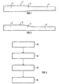
- Figure 1 depicts a slab 1 with a varying thickness.
- the slab has a large size portion 2 and a small size portion 4, with the slab in the region of the large size portion 2 being thicker than in the region of the small size portion 4.
- a region of varying thickness i.e., a tapered piece 3, which makes up the thickness transition between the small size portion 4 and the large size portion 2.
- These tapered pieces are usually removed, and the large size portion 2 and the small size portion 4 are rolled separately.
- the slab 1 can be continually rolled while maintaining a high quality without having to sever the slab in the area of the tapered piece 3.
- Figure 2 shows a slab 1 having a varying thickness as an alternative to the slab of Figure 1. It likewise has a large size portion 2 and a small size portion 4. Between the region of the large size portion 2 and the region of the small size portion 4 of the slab 1 is likewise a region of a varying thickness, the tapered piece 3.
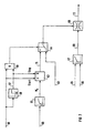
- FIG. 3 shows a system according to the invention for rolling slabs of different thickness while maintaining a high quality.
- the system has two roll stands: a first roll stand 6 and a second roll stand 7 for rolling the slab 5.
- the roll gap position of the roll stands 6 and 7 is adjusted by control elements 8 and 9.
- the roll gap of the roll stand 8 is controlled by the control element 8 so as to maintain a constant thickness of the material between roll stands 6 and 7.
- the control element 8 also supplies a value for the roll force 12.
- the rotational roll speed for the first roll stand 6 is regulated by a rotational speed regulator 31, and the roll torque of the second roll stand 7 by a torque regulator 32.
- the speed regulator 31 has a current control section 19 and a speed control section 20.
- the torque regulator 32 has a current control section 28, a rotational-speed control section 29, and a torque control section 30.
- the system has one torque sensor 11 and 15 for each of the two roll stands 6 and 7.
- the system has one load-torque observer 21 and 14 associated with each roll stand 6 and 7.
- Each of the two load-torque observers 14 and 21 determines a value for the load torque 33 or 34 from values for the motor current 17 or 26 and the roll rotational speed 18 or 27.
- a tensile-force regulator 13 supplies the manipulated variables for the regulators 31 and 32, nominal speed 22 and nominal torque 23.
- Figure 4 illustrates a state transition diagram for a train of rolls, which is controlled with the method according to the invention.
- the train of rolls is initially in the state 40, i.e. , the state in which the slab is first rolled with the first roll stand, but has not yet reached the second roll stand.
- the values that are independent of the strip tension in a tension-free state are determined in the first roll stand for the roll force and the roll torque.
- the system turns to state 42.
- state 42 the slab is rolled by both roll stands, however, the nominal tension in the slab desired between the first arid the second roll stand is not yet reached.
- state 42 the rotational speed in the second roll stand is kept constant, and the torque in the first roll stand is regulated so as to build up the tension desired in the slab between the first and the second roll stand. If the desired tension is reached in the slab between the first and the second roll stand, then the system turns to state 43.
- the actual and nominal tension are advantageously not directly compared, but rather through a comparison between the actual roll torque and a reference torque. One can thus eliminate a tensile measurement.
- state 43 the rotational speeds of roll stands 6 and 7 are maintained constant until the nominal values for rolling torque of the roll stand 7 at steady-state tension are measured using the torque sensor 15 or the load torque observer 21.
- state 44 the rotational speed of the first roll stand and the torque of the second roll stand are kept constant.
- Figure 5 depicts a closed-loop control of rolling torque for the first roll stand.
- Input variables of the closed-loop control are the roll force 86 of the first roll stand, a signal 87, which indicates the slab being passed into the first roll stand, a signal 88, which indicates the slab being passed into the second roll stand, the roll torque 89 in the first roll stand, as well as a hold signal 90.
- the output variable of the closed-loop control is a manipulated variable 91 for the motor speed.
- the measured value of the roll force 86 is initially smoothed through two low-pass filters 73 and 74. Both low-pass filters 73 and 74 smooth the measured value of the roll force 86, however, they can be realized with different time constants.
- an average value is generated in a signal averager 75.
- the averaging takes place during the time in which the slab is passed into the first roll stand, but not yet into the second roll stand.
- the averager 75 is fed the signal 87, which signals the guiding of the slab into the first roll stand, and the signal 88, which signals the guiding of the slab into the second roll stand.
- the output signal from the low-pass filter 73 is divided by the output signal from the averager 75.
- the measured value of the roll torque 89 of the first roll stand is likewise low-pass filtered.
- the control has two other low-pass filters 78 and 79, which smooth the measured value of the roll torque 89.
- the output signal from the low-pass filter 78 is fed to an averager 80, which generates an average value of the roll torque analogously to the averaging of the roll force by means of the averager 80.
- the output signal from the averager 80 is multiplied by the output signal from the divider 76 in a multiplication block 81. By multiplying the output signal from the multiplier 81 by a constant C in the multiplier 82, a reference torque M ref is attained, which is used as a variable that is equivalent to the strip tension for controlling strip tension.
- the reference torque M ref is fed as a setpoint variable to a PI controller 83.
- the PI-controller 83 receives the measured value of the roll torque 89, which is smoothed by the low-pass filter 79.
- the output signal from the PI controller 83 is smoothed in a low-pass filter 84.
- the output signal from the low-pass filter 84 is supplied to a switch 85.
- the switch 85 switches through the output signal from the low-pass filter 84 as a manipulated variable 91 for controlling the first roll stand speed after the slab has been passed into the second roll stand.
- a signal 92 which is applied to the output of an AND gate 77 for gating the signals 87 and 88, is fed to the switch 85.
- a hold signal 90 which holds the integrator of the PI-controller 83 to a value that corresponds to the maximum motor torque, is fed to the PI-controller 83.
- Figure 6 illustrates a closed-loop control structure for controlling torque in the second roll stand.
- the measured value of the torque 50 in the second roll stand is initially smoothed in two low-pass filters 45 and 46.
- a setpoint value M AV for the torque in the second roll stand is generated from the signal of the roll torque of the second roll stand smoothed by the low-pass filter 45.
- the average value is generated by applying a signal 52 which signals that the nominal tension in the slab has been reached.
- the signal 52 is fed to a lag element 51, which delays the signal 52 over N sampling steps. After the N sampling steps have elapsed, the average value generation in the averager 44 is halted.
- the setpoint value M AV i.e., the time average of the smoothed measured values M K , forms the setpoint variable for a downstream PI controller 47. Therefore, the setpoint value M AV is generated in accordance with the equation:
- the values 56, 57 or 60 correspond to the values 52, 55 or 50 of Figure 6, and the functional blocks 58, 59, 61 or 62 correspond to the functional blocks 51, 54, 45 or 44 of Figure 6.
- the averager 62 of Figure 7 does not calculate a single value for the nominal torque M AV , but rather an upper and a lower limit for limiting the motor current for the second roll stand. These limits amount advantageously to ⁇ 1 % of the nominal torque M AV .
- standard limits 63 Until the average value generation in the averager 62 is concluded, one works with standard limits 63. After conclusion of the averaging, the switch-over is made by means of the switch 64 from standard limits 63 to the limits 71 produced by the averager 62.
- the motor current 68 for driving the second roll stand is determined by a PI-speed controller 67, which is supplied with a setpoint value for the motor speed 65 and with a measured value of the rotational speed 66.
- the PI-controller 67 stipulates the setpoint value for the motor current 68 in the form of a manipulated variable 72 only when said manipulated variable 72 is not restricted by the limiter 69.
- the block diagram of Figure 7 functions in the manner of a transfer circuit, the rotational-speed closed-loop control being overridden by a torque open-loop control, represented by the functional blocks 58, 59, 61, 62 and 64.
Landscapes
- Engineering & Computer Science (AREA)
- Mechanical Engineering (AREA)
- Control Of Metal Rolling (AREA)
- Metal Rolling (AREA)
- Heat Treatment Of Steel (AREA)
Claims (6)
- Verfahren zum Walzen einer Bramme (1; 5), die über ihre Länge eine veränderliche Dicke aufweist, die durch das Gießen einer Bramme wegen unterschiedlicher, an die Qualität des Stahls gestellter Anforderungen auftritt, unter Verwendung eines ersten und eines zweiten Walzgerüsts (6, 7) mit folgenden Schritten: Vorwärtsbewegen der Bramme (1; 5) durch das erste und zweite Walzgerüst (6, 7) und mittels eines RegelmechanismusAufrechterhalten eines im wesentlichen konstanten, niedrigen Zugs in der Bramme (1; 5) zwischen dem ersten und zweiten Walzgerüst (6, 7) und Aufrechterhalten einer im wesentlichen konstanten Dicke der Bramme (1; 5) am Ausgang beider Walzgerüste (6, 7);außerdem mit dem im wesentlichen konstant Halten der Drehzahl des ersten Walzgerüsts (6) und des zweiten Walzgerüsts (7),außerdem mit dem Aufrechterhalten einer im wesentlichen konstanten Drehzahl des zweiten Walzgerüsts (7) und der Regelung eines Drehmoments des ersten Walzgerüsts (6) bis der im wesentlichen konstante Zug in der Bramme (1; 5) zwischen dem ersten und zweiten Walzgerüst (6, 7) erreicht ist.
- Verfahren nach Anspruch 1, wobei ein Referenzmomentwert (Mref) aus dem erwünschten Zug und der Walzkraft (Fw1) am ersten Walzgerüst (6) ermittelt wird.
- Verfahren nach Anspruch 2, wobei der Referenzmomentwert gemäß folgender Gleichung ermittelt wird:
- Fw1
- die aktive Walzkraft in dem ersten Walzgerüst (6) ist:
- Fw1,AV
- die Walzkraft in dem ersten Walzgerüst (6) ist, bevor die Bramme (1; 5) das zweite Walzgerüst (7) erreicht;
- Mw1,Av
- das Drehmoment im ersten Walzgerüst (6) ist, bevor die Bramme (1; 5) das zweite Walzgerüst (7) erreicht; und
- C
- ein Faktor zur Anpassung des erwünschten Sollzugs ist.
- Verfahren nach Anspruch 3, wobei der Faktor C aus folgender Gleichung ermittelt wird:
- R1
- der Walzdurchmesser des ersten Walzgerüsts (6), und
- Tref
- der erwünschte Sollzug in der Bramme (1; 5) zwischen dem ersten und zweiten Walzgerüst (6, 7) ist.
- System zum Walzen einer Bramme (1; 5), die über ihre Länge in der Dicke variiert, was durch das Gießen einer Bramme wegen unterschiedlicher, an die Qualität des Stahls gerichteter Anforderungen auftritt, und mit:der einen im wesentlichen konstanten, niedrigen Zug in der Bramme (1; 5) zwischen dem ersten und zweiten Walzgerüst (6, 7) aufrechterhält,zumindest zwei Walzgerüsten (6, 7) und Mitteln zum Vorwärtsbewegen einer Bramme (1; 5) durch das erste und zweite Walzgerüst (6, 7),einem Regelmechanismus,
der eine im wesentlichen konstante Dicke des Materials an den Ausgängen beider Walzgerüste (6, 7) aufrechterhält,
der die Drehzahl des ersten Walzgerüsts (6) und das Drehmoment des zweiten Walzgerüsts (7) im wesentlichen konstant hält, nachdem der erwünschte, im wesentlichen konstante Zug in der Bramme (1; 5) zwischen dem ersten und zweiten Walzgerüst (6, 7) erreicht ist,
der eine im wesentlichen konstante Geschwindigkeit des zweiten Walzgerüsts (7) aufrechterhält und das Drehmoment des ersten Walzgerüsts (6) regelt, bis der erwünschte, im wesentlichen konstante Zug in der Bramme (1; 5) zwischen dem ersten und zweiten Walzgerüst (6, 7) erreicht ist. - System nach Anspruch 5 außerdem mit einer Auswerteeinheit.
Priority Applications (1)
| Application Number | Priority Date | Filing Date | Title |
|---|---|---|---|
| EP97900997A EP0876227B1 (de) | 1996-01-23 | 1997-01-10 | System und verfahren zum walzen von brammen |
Applications Claiming Priority (4)
| Application Number | Priority Date | Filing Date | Title |
|---|---|---|---|
| EP96100923 | 1996-01-23 | ||
| EP96100923 | 1996-01-23 | ||
| PCT/EP1997/000098 WO1997027012A1 (en) | 1996-01-23 | 1997-01-10 | System and method for rolling slabs |
| EP97900997A EP0876227B1 (de) | 1996-01-23 | 1997-01-10 | System und verfahren zum walzen von brammen |
Publications (2)
| Publication Number | Publication Date |
|---|---|
| EP0876227A1 EP0876227A1 (de) | 1998-11-11 |
| EP0876227B1 true EP0876227B1 (de) | 2003-04-09 |
Family
ID=8222426
Family Applications (1)
| Application Number | Title | Priority Date | Filing Date |
|---|---|---|---|
| EP97900997A Expired - Lifetime EP0876227B1 (de) | 1996-01-23 | 1997-01-10 | System und verfahren zum walzen von brammen |
Country Status (5)
| Country | Link |
|---|---|
| EP (1) | EP0876227B1 (de) |
| KR (1) | KR100477238B1 (de) |
| AT (1) | ATE236740T1 (de) |
| DE (1) | DE69720689T2 (de) |
| WO (1) | WO1997027012A1 (de) |
Families Citing this family (4)
| Publication number | Priority date | Publication date | Assignee | Title |
|---|---|---|---|---|
| RU2135314C1 (ru) * | 1998-03-12 | 1999-08-27 | Галкин Михаил Петрович | Способ автоматического управления процессом непрерывной прокатки с минимальным натяжением или подпором сортового металла |
| RU2147951C1 (ru) * | 1999-06-07 | 2000-04-27 | Открытое акционерное общество "Магнитогорский металлургический комбинат" | Система автоматического регулирования межклетевого натяжения полосы |
| CN101602068B (zh) * | 2009-07-07 | 2011-08-17 | 东北大学 | 周期性变厚度带材轧制过程中张力的控制方法及控制系统 |
| RU2437731C1 (ru) * | 2010-05-14 | 2011-12-27 | Закрытое акционерное общество "Автоматизированные системы и комплексы" | Способ автоматического управления процессом непрерывной прокатки сортового металла с минимальным натяжением или подпором металла между клетями |
Family Cites Families (11)
| Publication number | Priority date | Publication date | Assignee | Title |
|---|---|---|---|---|
| NL274832A (de) * | ||||
| DE1427804A1 (de) * | 1958-12-29 | 1969-03-27 | Stich Dr Ing Wilhelm | Verfahren zum Betrieb einer kontinuierlichen Warmband-Fertigstrasse |
| DE1602203A1 (de) * | 1967-03-28 | 1970-04-16 | Wissenschaftlich Tech Zentrum | Antrieb fuer Walz- und Rollenrichtmaschinen |
| US3807206A (en) * | 1972-09-29 | 1974-04-30 | J Connors | Strip gage change during rolling in a tanden rolling mill |
| FR2354154A1 (fr) * | 1976-06-11 | 1978-01-06 | Jeumont Schneider | Procede pour le laminage sans contrainte de metaux et dispositif pour la mise en oeuvre de ce procede |
| AU493666B2 (en) * | 1976-07-16 | 1976-09-30 | Hitachi Limited | Interstand tension control method and apparatus for tandem rolling mills |
| JPS56114522A (en) * | 1980-02-13 | 1981-09-09 | Kikai Syst Shinko Kyokai | Speed control method of direct rolling mill |
| FR2483268A1 (fr) * | 1980-05-28 | 1981-12-04 | Jeumont Schneider | Procede et dispositif pour le laminage sans ccontrainte de metaux |
| JPS58205609A (ja) * | 1982-05-25 | 1983-11-30 | Toshiba Corp | 連続圧延機の制御装置 |
| JPS58218304A (ja) * | 1982-06-14 | 1983-12-19 | Hitachi Ltd | 連続鋳造設備の制御装置 |
| DE3839151A1 (de) * | 1988-11-17 | 1990-05-23 | Mannesmann Ag | Verfahren zum herstellen von warmgewalztem stahlband aus einem bandfoermig stranggegossenem vormaterial |
-
1997
- 1997-01-10 AT AT97900997T patent/ATE236740T1/de active
- 1997-01-10 EP EP97900997A patent/EP0876227B1/de not_active Expired - Lifetime
- 1997-01-10 KR KR10-1998-0705942A patent/KR100477238B1/ko not_active Expired - Fee Related
- 1997-01-10 DE DE69720689T patent/DE69720689T2/de not_active Expired - Lifetime
- 1997-01-10 WO PCT/EP1997/000098 patent/WO1997027012A1/en not_active Ceased
Also Published As
| Publication number | Publication date |
|---|---|
| ATE236740T1 (de) | 2003-04-15 |
| WO1997027012A1 (en) | 1997-07-31 |
| EP0876227A1 (de) | 1998-11-11 |
| KR19990082214A (ko) | 1999-11-25 |
| KR100477238B1 (ko) | 2005-07-12 |
| DE69720689T2 (de) | 2003-12-24 |
| DE69720689D1 (de) | 2003-05-15 |
Similar Documents
| Publication | Publication Date | Title |
|---|---|---|
| US5806357A (en) | System and method for rolling tapered slabs | |
| EP0130551B1 (de) | Regelverfahren und Vorrichtung für ein Walzwerk | |
| US5012660A (en) | Control system and method for compensating for speed effect in a tandem cold mill | |
| CN107073534B (zh) | 用于铸造和轧制无头连铸坯材的方法和铸造轧制设备 | |
| RU2220799C2 (ru) | Горячепрокатный стан стеккеля | |
| EP0876227B1 (de) | System und verfahren zum walzen von brammen | |
| JPH08281313A (ja) | フォイル圧延における厚さ予制御方法及び装置 | |
| KR100545491B1 (ko) | 금속 스트립의 절삭 방법 및 장치 | |
| JP3255785B2 (ja) | タンデム圧延機における板厚制御方法 | |
| JP3345311B2 (ja) | 圧延機駆動用電動機の速度制御装置 | |
| SU1738400A1 (ru) | Способ регулировани межклетевого нат жени и устройство дл его осуществлени | |
| JP3684091B2 (ja) | カーテンコーターに於ける塗装品質保証方法 | |
| JPS58218304A (ja) | 連続鋳造設備の制御装置 | |
| JPH02142610A (ja) | 圧延機の自動板厚制御装置 | |
| US6922878B1 (en) | Method and device for rolling a foil of varying thicknesses | |
| SU1154016A2 (ru) | Устройство дл автоматической настройки прокатной клети | |
| JPH09239417A (ja) | 熱間圧延機の制御装置 | |
| JP3085851B2 (ja) | 熱間圧延機のモデル同定装置及び制御装置 | |
| SU1752461A1 (ru) | Устройство дл управлени скоростью клетей непрерывного стана холодной прокатки полосы | |
| RU2158469C2 (ru) | Многодвигательный электропривод многократного прямоточного волочильного стана | |
| RU2065790C1 (ru) | Система "тонкого" регулирования толщины полосы на непрерывном стане холодной прокатки | |
| JPS6215287B2 (de) | ||
| JPH0773734B2 (ja) | タンデムミルの速度制御装置 | |
| KR20040019725A (ko) | 스트랜드 구동롤의 부하배분을 위한 제어방법 | |
| JPH0364205B2 (de) |
Legal Events
| Date | Code | Title | Description |
|---|---|---|---|
| PUAI | Public reference made under article 153(3) epc to a published international application that has entered the european phase |
Free format text: ORIGINAL CODE: 0009012 |
|
| 17P | Request for examination filed |
Effective date: 19980720 |
|
| AK | Designated contracting states |
Kind code of ref document: A1 Designated state(s): AT BE DE FR SE |
|
| 17Q | First examination report despatched |
Effective date: 19991116 |
|
| GRAH | Despatch of communication of intention to grant a patent |
Free format text: ORIGINAL CODE: EPIDOS IGRA |
|
| GRAH | Despatch of communication of intention to grant a patent |
Free format text: ORIGINAL CODE: EPIDOS IGRA |
|
| GRAA | (expected) grant |
Free format text: ORIGINAL CODE: 0009210 |
|
| AK | Designated contracting states |
Designated state(s): AT BE DE FR SE |
|
| REG | Reference to a national code |
Ref country code: SE Ref legal event code: TRGR |
|
| ET | Fr: translation filed | ||
| PLBE | No opposition filed within time limit |
Free format text: ORIGINAL CODE: 0009261 |
|
| STAA | Information on the status of an ep patent application or granted ep patent |
Free format text: STATUS: NO OPPOSITION FILED WITHIN TIME LIMIT |
|
| 26N | No opposition filed |
Effective date: 20040112 |
|
| PGFP | Annual fee paid to national office [announced via postgrant information from national office to epo] |
Ref country code: FR Payment date: 20120126 Year of fee payment: 16 |
|
| PGFP | Annual fee paid to national office [announced via postgrant information from national office to epo] |
Ref country code: BE Payment date: 20120210 Year of fee payment: 16 Ref country code: SE Payment date: 20120110 Year of fee payment: 16 |
|
| PGFP | Annual fee paid to national office [announced via postgrant information from national office to epo] |
Ref country code: AT Payment date: 20111214 Year of fee payment: 16 |
|
| PGFP | Annual fee paid to national office [announced via postgrant information from national office to epo] |
Ref country code: DE Payment date: 20130318 Year of fee payment: 17 |
|
| BERE | Be: lapsed |
Owner name: *SIEMENS A.G. Effective date: 20130131 |
|
| REG | Reference to a national code |
Ref country code: SE Ref legal event code: EUG |
|
| REG | Reference to a national code |
Ref country code: AT Ref legal event code: MM01 Ref document number: 236740 Country of ref document: AT Kind code of ref document: T Effective date: 20130131 |
|
| REG | Reference to a national code |
Ref country code: FR Ref legal event code: ST Effective date: 20130930 |
|
| PG25 | Lapsed in a contracting state [announced via postgrant information from national office to epo] |
Ref country code: AT Free format text: LAPSE BECAUSE OF NON-PAYMENT OF DUE FEES Effective date: 20130131 Ref country code: BE Free format text: LAPSE BECAUSE OF NON-PAYMENT OF DUE FEES Effective date: 20130131 Ref country code: SE Free format text: LAPSE BECAUSE OF NON-PAYMENT OF DUE FEES Effective date: 20130111 |
|
| PG25 | Lapsed in a contracting state [announced via postgrant information from national office to epo] |
Ref country code: FR Free format text: LAPSE BECAUSE OF NON-PAYMENT OF DUE FEES Effective date: 20130131 |
|
| REG | Reference to a national code |
Ref country code: DE Ref legal event code: R119 Ref document number: 69720689 Country of ref document: DE |
|
| REG | Reference to a national code |
Ref country code: DE Ref legal event code: R119 Ref document number: 69720689 Country of ref document: DE Effective date: 20140801 |
|
| PG25 | Lapsed in a contracting state [announced via postgrant information from national office to epo] |
Ref country code: DE Free format text: LAPSE BECAUSE OF NON-PAYMENT OF DUE FEES Effective date: 20140801 |