EP0876265B1 - Stossdämpfer und herstellungsverfahren - Google Patents
Stossdämpfer und herstellungsverfahren Download PDFInfo
- Publication number
- EP0876265B1 EP0876265B1 EP97901848A EP97901848A EP0876265B1 EP 0876265 B1 EP0876265 B1 EP 0876265B1 EP 97901848 A EP97901848 A EP 97901848A EP 97901848 A EP97901848 A EP 97901848A EP 0876265 B1 EP0876265 B1 EP 0876265B1
- Authority
- EP
- European Patent Office
- Prior art keywords
- portions
- section
- bumper
- blank
- wall portion
- Prior art date
- Legal status (The legal status is an assumption and is not a legal conclusion. Google has not performed a legal analysis and makes no representation as to the accuracy of the status listed.)
- Expired - Lifetime
Links
- 238000004519 manufacturing process Methods 0.000 title claims description 7
- 238000000034 method Methods 0.000 claims description 23
- 239000000463 material Substances 0.000 claims description 8
- 238000003825 pressing Methods 0.000 claims description 2
- 230000002349 favourable effect Effects 0.000 description 8
- 238000005452 bending Methods 0.000 description 3
- 230000000694 effects Effects 0.000 description 2
- 238000009877 rendering Methods 0.000 description 2
- XAGFODPZIPBFFR-UHFFFAOYSA-N aluminium Chemical compound [Al] XAGFODPZIPBFFR-UHFFFAOYSA-N 0.000 description 1
- 229910052782 aluminium Inorganic materials 0.000 description 1
- 230000004888 barrier function Effects 0.000 description 1
- 230000006835 compression Effects 0.000 description 1
- 238000007906 compression Methods 0.000 description 1
- 230000001419 dependent effect Effects 0.000 description 1
- 238000009826 distribution Methods 0.000 description 1
- ZZUFCTLCJUWOSV-UHFFFAOYSA-N furosemide Chemical compound C1=C(Cl)C(S(=O)(=O)N)=CC(C(O)=O)=C1NCC1=CC=CO1 ZZUFCTLCJUWOSV-UHFFFAOYSA-N 0.000 description 1
- 239000011796 hollow space material Substances 0.000 description 1
- 239000000203 mixture Substances 0.000 description 1
- 230000007704 transition Effects 0.000 description 1
Images


Classifications
-
- B—PERFORMING OPERATIONS; TRANSPORTING
- B60—VEHICLES IN GENERAL
- B60R—VEHICLES, VEHICLE FITTINGS, OR VEHICLE PARTS, NOT OTHERWISE PROVIDED FOR
- B60R19/00—Wheel guards; Radiator guards, e.g. grilles; Obstruction removers; Fittings damping bouncing force in collisions
- B60R19/02—Bumpers, i.e. impact receiving or absorbing members for protecting vehicles or fending off blows from other vehicles or objects
- B60R19/18—Bumpers, i.e. impact receiving or absorbing members for protecting vehicles or fending off blows from other vehicles or objects characterised by the cross-section; Means within the bumper to absorb impact
-
- B—PERFORMING OPERATIONS; TRANSPORTING
- B60—VEHICLES IN GENERAL
- B60R—VEHICLES, VEHICLE FITTINGS, OR VEHICLE PARTS, NOT OTHERWISE PROVIDED FOR
- B60R19/00—Wheel guards; Radiator guards, e.g. grilles; Obstruction removers; Fittings damping bouncing force in collisions
- B60R19/02—Bumpers, i.e. impact receiving or absorbing members for protecting vehicles or fending off blows from other vehicles or objects
- B60R19/18—Bumpers, i.e. impact receiving or absorbing members for protecting vehicles or fending off blows from other vehicles or objects characterised by the cross-section; Means within the bumper to absorb impact
- B60R2019/1806—Structural beams therefor, e.g. shock-absorbing
- B60R2019/1813—Structural beams therefor, e.g. shock-absorbing made of metal
-
- B—PERFORMING OPERATIONS; TRANSPORTING
- B60—VEHICLES IN GENERAL
- B60R—VEHICLES, VEHICLE FITTINGS, OR VEHICLE PARTS, NOT OTHERWISE PROVIDED FOR
- B60R19/00—Wheel guards; Radiator guards, e.g. grilles; Obstruction removers; Fittings damping bouncing force in collisions
- B60R19/02—Bumpers, i.e. impact receiving or absorbing members for protecting vehicles or fending off blows from other vehicles or objects
- B60R19/18—Bumpers, i.e. impact receiving or absorbing members for protecting vehicles or fending off blows from other vehicles or objects characterised by the cross-section; Means within the bumper to absorb impact
- B60R2019/1806—Structural beams therefor, e.g. shock-absorbing
- B60R2019/1813—Structural beams therefor, e.g. shock-absorbing made of metal
- B60R2019/182—Structural beams therefor, e.g. shock-absorbing made of metal of light metal, e.g. extruded
Definitions
- the present invention relates to a method for fabrication of a structural beam or bumper according to the precharacterizing clause of claim 1. Such a method is known from WO93/04897.
- the invention relates to a beam or bumper, fabricated by the said method.
- the cross-section of a center portion may be a lot larger than of terminal portions. Therefore, it is necessary to compress the terminal portions to a very high extent.
- the motive of the present invention is the task of providing a bumper which combines the protection of a vehicle and persons in the vehicle upon collision.
- the invention has for its objective to provide a bumper which excels in high torsional stiffness, combined with great bending softness.
- a further objective of the present invention is to provide a bumper rendering the possibility for rational and structural sturdy attachment to the frame of the vehicle.
- An object of the present invention is also to provide an elastic and relatively slender structural beam or bumper which in relation to previously known profile based, closed bumpers, may absorb more elastic bending energy in relation to quantity of used material.
- the invention relates to a method which renders a rational production of bumpers of said type, the method at the same time being specifically favourable for high rate forming in a production line.
- a specific embodiment of such a bumper may involve that the cross section at each side of the centre comprises an outer wall portion, an arched inner wall portion, as well as yoke portions extending substantially perpendicularly from said outer wall portion that said cross section at the centre has a substantially trapeze shaped cross section comprising an outer wall portion having substantially the same hight as said intermediate cross section and an inner wall portion of lesser hight, as well as substantially slanted yoke portions therebetween, and that said cross section at the terminal portions has an outer wall portion having substantially the same hight as said intermediate cross section and an inner wall portion having larger, equal or less hight and having intermediate, arched or wavy yoke portions.
- the trapeze shaped cross section at the centre can then by simple processing of the original yoke portions and the arched surfaces of the inner wall be given a predetermined shape, at the same time as said basic cross section at each side of the centre will allow for easier manipulation of the shape of the product. Further, with said basic cross section on each side of the centre it is possible to undertake a controlled compression for folding of the areas at each of the terminal portions, so that the latter constitute the more slender part of the bumper.
- this type of bumper comprises a closed cross section having a front wall portion, a rear wall portion and intermediate yoke portions, said front and rear portions having a relatively large wall thickness compared to the wall thickness of the intermediate yoke portions.
- front wall portion can be substantially straight, or be provided with a more or less contoured shape.
- terminal portions may be so prepared that they merge into attachment portions which are provided with individual parallel surfaces against associated side beam for attachment thereto.
- the bumper may be prepared substantially symmetrically about a central plane extending in the longitudinal direction of the car, and be provided with an outer mantle of plastic material.
- a method for manufacturing a structural beam or bumper of the type as stated in the preamble will involve starting off with an extruded profile having a given basic cross section and by the further processing of this profiled blank letting the latter basic cross section be maintained on each side of the centre, whereas in the area of the centre letting the basic cross section be processed to a more or less protruding cross section, at the same time as letting the profile at the terminal portions be processed to a more compressed or folded cross section.
- the method is to the fact that one starts off with a cross section which at each side of the centre has an intermediate cross section comprising an outer wall portion, an arched inner wall portion, as well as yoke portions extending substantially perpendicularly from the outer wall portion, that the cross section at the centre is processed by substantially outwardly pressing of the yoke portion for the provision of a substantially trapeze shaped cross section comprising an outer wall portion having substantially the same hight as the intermediate cross section and an inner wall portion of smaller hight, as well as substantially inclined yoke portions therebetween, and that at the terminal portions the intermediate cross section is processed to an outer wall portion having substantially the same hight as said intermediate cross section and an inner wall portion having larger, equal or less hight, the intermediate yoke being processed to bulge or bend outwardly in relation to said outer wall portion.
- the extruded blank to be used which has a closed cross section and a front wall portion and a rear wall portion, as well as intermediate yoke portions, also has front and rear wall portions having a relatively larger wall thickness of said intermediate yoke portions.
- the front wall portion may be substantially straight, or have a more or less contoured form.
- terminal portions may be further processed or simultaneously processed to comprise attachment portions which are provided with a net parallel surface related to appropriate side beams of the vehicle.
- the method is to the fact of manufacturing a bumper profile which is substantially symmetrical about a centre plane extending in the longitudinal direction of the car, at the same time as the finished bumper will be provided with an outer mantle of plastic material.
- a further feature according to the method according to the invention is to the fact that the bumper is manufactured by outer processing, said outer processing taking place by means of mechanical tools.
- hydroforming can be used.
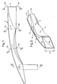
- Fig. 1 is a schematic view as seen from above of a symmetrical half of a structural beam, especially a bumper beam according to the invention.
- Fig. 2 is a side view of the bumper rail half according to Fig. 1.
- Fig. 3 is a perspective view of a cut-out of the terminal portion of the bumper rail illustrated in Figures 1 and 2.
- Figures 4, 5, 6 and 7 are cross sections taken along the lines IV-IV, V-V, VI-VI as well as VII-VII, respectively, according to Fig. 1.
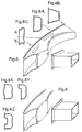
- Fig. 8 is a perspective view of a bumper rail having a specifically formed terminal portion for net parallel attachment, Figures 8A, 8B and 8C defining the various cross section forms along said bumper rail, Figures 8AX, 8AY and 8AZ defining various forms of the outer wall portion.
- Fig. 9 is a perspective cut-out of a terminal portion of a bumper rail provided with attachment portions for non-net parallel attachment.
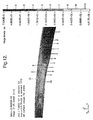
- Figures 10-12 illustrate examples of calculation models for an embodiment of a structural beam according to the invention, said model being compiled according to the "finite element" method.
- FIGs 1-7 there is illustrated an example of a structural beam, especially a bumper beam according to the invention, Fig. 1 illustrating schematically a view as seen from above of a symmetric half of said rail 1, whereas Fig. 2 illustrates a side view of the same rail, and Fig. 3 illustrates perspectively details of the terminal portion of the bumper rail 1 illustrated in Figures 1 and 2.
- Figures 4, 5, 6 and 7 represent cross sections taken along the lines IV-IV, V-V, VI-VI, as well as VII-VII, respectively, illustrated in Fig. 1.
- the bumper rail 1 is in Figures 1-7 illustrated in its finished processed form, and is as such adapted for absorbing collision energy and forces when used in a car, it being preferably as a bumper, but also as a supporting beam in the overall structure of the car.
- the bumper 1 is made from a complete and hollow extruded blank which is manufactured from an extrudable material, for example aluminum, or any other materials or mixtures having corresponding extrudable and strength-related properties.
- the blank has in its initial form a basic cross section 2 of the type which is specifically illustrated in Fig. 4, and which comprises an outer wall portion 2a of substantially straight design and having a hight H, an arched inner portion 2b as well as yoke portions 2c extending substantially perpendicularly from the outer wall portion 2a.
- This basic cross section 2 is on both sides of the centre, see IV-IV in Fig. 1 and Fig. 4, according to the present invention maintained so to say unchanged, whereas at the centre portion itself, see V-V in Fig. 1 and Fig.
- the basic cross section has been given an outwardly pressed cross section 3, whereas in the areas of each of the terminal portions, here at section VI-VI in Fig. 1, see also Fig. 6, the basic cross section 2 has been compressed or folded to a further cross section 4, which is different from the basic cross section.
- the bumper rail 1 is manufactured on the basis of a basic cross section on each side of the centre, and an outwardly pressed cross section at the centre in relation to said basic cross section, as well as a compressed or folded cross section in the areas of each of the terminal portions.
- outer wall portion can deviate from the wall portion 2a as illustrated here, namely by being substantially straight, or be designed with a more or less contoured shape.
- the cross section 3 at the centre is pressed out to a substantially trapeze shaped cross section 3, comprising a straight inner wall portion 3a having substantially the same hight H as said inner wall portion 2b of said intermediate cross section 2, and having an inner wall portion 3b of lesser hight, at the same time as there are provided substantially inclined yoke portions 3c between said straight inner wall portion 3a and said outer wall portion 3b.
- the cross section 4 at the terminal portions, see specifically Fig. 6, is in this embodiment compressed or folded to comprise a straight outer wall portion 4a having substantially the same hight H as the outer wall portion 2a for said intermediate cross section 2, see Fig. 4, as well as an inner wall portion 4b which is here folded out to a larger hight H1 than said outer wall portion 4a, and then with intermediate arched or wavy yoke portions 4c.
- cross section 4 at the terminal portions can have an inner wall portion which can be equal or less than said hight corresponding to the hight H for said intermediate cross section 2, all in dependence of the desired final form which the bumper or the power beam according to the present invention is to be given.
- the starting point is a cross section 2, see Fig. 4, which constitutes a closed cross section, the front wall portion 2a and the rear wall portion 2b being provided with or comprising portions having a larger wall thickness than the wall thickness of the intermediate yoke portions 2c.
- profile or bumper rail 1 can be made substantially symmetrical about a centre plane running in the longitudinal direction of the vehicle, and beyond this be provided with an outer mantle of plastic material.
- the structural beam according to the invention is to be used as a structure element in the vehicle as such, this symmetrical design can appropriately be alleviated.
- terminal portions may merge into attachment portions, as this is specifically illustrated in Figures 8 and 9, said attachment portions being provided with a net parallel surface against side beams of the vehicle.
- Fig. 8 with its sections 8A-8C illustrates a specific design of the terminal portions for net parallel attachment, and the sections illustrated in Figures 8A, 8B and 8C are designed substantially in accordance with the sections as discussed in connection with Figures 4, 5 and 6. However, in Fig. 8C there are illustrated alternative a and alternative b for various bendings of the processed section 5 at the terminal portions.
- Fig. 8AX illustrated a variant of the basic cross section comprising an outer portion which deviates from being straight, but which rather has an outwardly bulging contour
- Fig. 8AY illustrates an asymmetrical outer portion
- Fig. 8AZ illustrates a substantially mirror symmetrical section having an inwardly bulging contour.
- Fig. 9 there is illustrates a perspective view of a terminal portion of a bumper rail provided with attachment portions for non-net parallel attachment.
- the processing of the blank can take place by a first stretching to the basic shape, especially a modestly arched shape in the longitudinal direction of the blank, whereafter the profile is simultaneously processed at the centre portion and the terminal portions, but with the opposite processing direction for said portions.
- said processing may be to the fact that the blank is processed by means of hydroforming.
- Figures 10-12 there is illustrated examples of calculated models of an embodiment of a structural beam according to the invention.
- Figures 10 and 11 illustrate various perspective views of the model which is compiled according to the "finite element" method.
- Fig. 12 illustrates the stress distribution in load case “barrier", and then more specifically equivalent stresses at "fringe” levels.
Landscapes
- Engineering & Computer Science (AREA)
- Mechanical Engineering (AREA)
- Body Structure For Vehicles (AREA)
Claims (16)
- Verfahren zur Herstellung eines Strukturträgers oder Stoßfängers, insbesondere für ein Fahrzeug, wobei er ein längliches Profil aufweist, welches bei einer Kollision zum Absorbieren von Kollisionsenergie und -kräften dient,
wobei das Verfahren folgende Schritte umfasst:ein komplettes und hohles Rohmaterialstück wird bereitgestellt, welches entlang seines mehr oder weniger bogenförmigen Verlaufes einen Mittelabschnitt (3), Seitenabschnitte (2) auf jeder Seite des Mittelabschnittes (3) und Endabschnitte (4) aufweist, unddas Rohmaterialstück wird beim Endabschnitt (4) zu einem zusammengedrückten oder gefalteten Querschnitt verarbeitet;und durch die folgenden Schritte gekennzeichnet ist:das Rohmaterialstück wird beim Mittelabschnitt (3) zu einem nach außen gedrückten Querschnitt verarbeitet unddas Rohmaterialstück wird mit einem im Wesentlichen unveränderten Basisquerschnitt in jedem Seitenabschnitt (2) verarbeitet. - Verfahren nach Anspruch 1,
gekennzeichnet durch einen Schritt, bei dem das Rohmaterialstück zu einem bogenförmigen Verlauf verarbeitet wird. - Verfahren nach Anspruch 1 oder 2,
dadurch gekennzeichnet, dass ein hohles Rohmaterialstück verwendet wird, dessen Inneres durch einen ersten Wandabschnitt (2a), einen bogenförmigen zweiten Wandabschnitt (2b) und Jochabschnitte (2c), die sich im Wesentlichen senkrecht vom Außenwandabschnitt (2a) erstrecken, begrenzt wird, wobei
der Mittelabschnitt (3) zu einem im Wesentlichen trapezförmigen Querschnitt verarbeitet wird, welcher einen ersten Wandabschnitt (3a), der im Wesentlichen die gleiche Höhe (H) wie das Rohmaterialstück besitzt, einen zweiten mittleren Wandabschnitt (3b) geringerer Höhe, und zwischen diesen befindliche im Wesentlichen geneigte mittlere Jochabschnitte (3c) aufweist, und
die Endabschnitte (4) zu einem Querschnittsprofil verarbeitet werden, welches einen ersten Endwandabschnitt (4a) von gleicher Höhe (H) wie das Rohmaterialstück, einen zweiten Endwandabschnitt (4b) von größerer, gleicher oder geringerer Höhe (H), und dazwischenliegende bogenförmige oder wellige Endjochabschnitte (4c) aufweist. - Verfahren nach einem der vorstehenden Ansprüche,
dadurch gekennzeichnet, dass als Rohmaterialstück ein Extrudierprofil (2) mit geschlossenem Querschnitt verwendet wird, wobei die ersten und zweiten Wandabschnitte (2a, 2b) eine größere Wanddicke als die dazwischenliegenden Jochabschnitte (2c) haben. - Verfahren nach einem der vorstehenden Ansprüche,
dadurch gekennzeichnet, dass die Endabschnitte des Rohmaterialstücks zu Befestigungsabschnitten verarbeitet sind, welche mit einer zum Netz parallelen Fläche zur Befestigung an einem Seitenträger im Fahrzeug versehen sind. - Verfahren nach einem der vorstehenden Ansprüche,
dadurch gekennzeichnet, dass das Rohmaterialstück zu einem Profil verarbeitet wird, welches im Wesentlichen symmetrisch um eine Mittelebene ist, die in Längsrichtung des Fahrzeugs verläuft, und mit einem Außenmantel aus Kunststoff versehen ist. - Verfahren nach einem der vorstehenden Ansprüche,
dadurch gekennzeichnet, dass die Bearbeitung des Rohmaterialstücks durch einen ersten Dehn- oder Pressvorgang zu einer Hauptform erfolgt, insbesondere zu einer in Längsrichtung des Rohmaterialstücks ungefähr bogenförmigen Form, und danach das Profil, gleichzeitig oder in einem aufeinanderfolgenden Bearbeitungsvorgängen, beim Mittelabschnitt (3) und den Endabschnitten (4) bearbeitet wird, jedoch für diese Abschnitte in entgegengesetzter Bearbeitungsrichtung. - Verfahren nach einem der vorstehenden Ansprüche,
dadurch gekennzeichnet, dass das Rohmaterialstück durch eine äußere Bearbeitung bearbeitet wird, beispielsweise mittels mechanischen Werkzeugen. - Verfahren nach einem der vorstehenden Ansprüche,
dadurch gekennzeichnet, dass das Rohmaterialstück mittels eines Hydroforming-Prozesses verarbeitet wird. - Strukturträger oder Stoßfänger, der mittels des Verfahrens nach einem der vorstehenden Ansprüche erzeugt wurde.
- Träger oder Stoßfänger nach Anspruch 10, insbesondere für ein Fahrzeug, welcher ein längliches Profil aufweist, das zum Absorbieren von Kollisionsenergie und -kräften bei einer Kollision dient, wobei der Träger oder Stoßfänger aus einem kompletten und hohlen Rohmaterialstück erzeugt ist und weiter mit unterschiedlichen Querschnitten entlang seines mehr oder weniger bogenförmigen Verlaufes versehen ist, wobei
der Träger oder Stoßfänger einen Mittelabschnitt (3), Seitenabschnitte (2) auf jeder Seite des Mittelabschnittes (3) und Endabschnitte (4) aufweist und
der Träger oder Stoßfänger bei jedem der Endabschnitte (4) einen zusammengedrückten oder gefalteten Querschnitt aufweist, und der Träger oder Stoßfänger bei jedem der Seitenabschnitte (2) außerdem einen im Wesentlichen unveränderten Basisquerschnitt aufweist, und beim Mittelabschnitt (3) einen relativ zum Basisquerschnitt nach außen gedrückten Querschnitt aufweist. - Träger oder Stoßfänger nach Anspruch 10 oder 11,
dadurch gekennzeichnet, dass
er einen bogenförmigen Verlauf hat. - Träger oder Stoßfänger nach einem der Ansprüche 10 bis 12,
dadurch gekennzeichnet, dass
das Inneres jedes der Seitenabschnitte (2) begrenzt ist durch einen ersten Wandabschnitt (2a), einen bogenförmigen Innenwandabschnitt (2b) und Jochabschnitte (2c), die sich im Wesentlichen senkrecht vom Außenwandabschnitt (2a) erstrecken,
der Mittelabschnitt (3) einen im Wesentlichen trapezförmigen Querschnitt, der begrenzt ist durch einen ersten mittleren Wandabschnitt (3a) von gleicher Höhe (H) wie die Seitenabschnitte (2), einen zweiten mittleren Wandabschnitt (3b) geringerer Höhe, und zwischen diesen befindliche im Wesentlichen geneigte Jochabschnitte (3c) aufweist, und
die Endabschnitte (4) einen ersten Endwandabschnitt (4a) von im Wesentlichen gleicher Höhe (H) wie die Seitenabschnitte (2), einen zweiten mittleren Endwandabschnitt (4b) von größerer, gleicher oder geringerer Höhe (H1) und dazwischenliegende bogenförmige oder wellige Jochabschnitte (4c) aufweisen. - Träger oder Stoßfänger nach einem der Ansprüche 10 bis 13,
dadurch gekennzeichnet, dass er einen geschlossenen Querschnitt (2) hat, wobei die ersten und zweiten Wandabschnitte (2a, 2b) eine relativ größere Wanddicke als die dazwischenliegenden Jochabschnitte (2c) haben. - Träger oder Stoßfänger nach einem der Ansprüche 10 bis 14,
dadurch gekennzeichnet, dass die Endabschnitte (4) in Befestigungsabschnitte münden, welche mit einer zum Netz parallelen Fläche zur Befestigung an einem Seitenträger im Fahrzeug versehen sind. - Träger oder Stoßfänger nach einem der Ansprüche 10 bis 15,
dadurch gekennzeichnet, dass
sein Profil im Wesentlichen symmetrisch um eine Mittelebene vorgesehen ist, die in Längsrichtung des Fahrzeugs verläuft, und
er mit einem Außenmantel aus Kunststoff versehen ist.
Applications Claiming Priority (3)
| Application Number | Priority Date | Filing Date | Title |
|---|---|---|---|
| NO960288 | 1996-01-24 | ||
| NO960288A NO960288D0 (no) | 1996-01-24 | 1996-01-24 | Stötfangerskinne |
| PCT/NO1997/000011 WO1997027082A1 (en) | 1996-01-24 | 1997-01-14 | Bumper, and the fabrication thereof |
Publications (2)
| Publication Number | Publication Date |
|---|---|
| EP0876265A1 EP0876265A1 (de) | 1998-11-11 |
| EP0876265B1 true EP0876265B1 (de) | 2002-08-14 |
Family
ID=19898962
Family Applications (1)
| Application Number | Title | Priority Date | Filing Date |
|---|---|---|---|
| EP97901848A Expired - Lifetime EP0876265B1 (de) | 1996-01-24 | 1997-01-14 | Stossdämpfer und herstellungsverfahren |
Country Status (6)
| Country | Link |
|---|---|
| US (1) | US5997058A (de) |
| EP (1) | EP0876265B1 (de) |
| AU (1) | AU1559897A (de) |
| DE (1) | DE69714705T2 (de) |
| NO (1) | NO960288D0 (de) |
| WO (1) | WO1997027082A1 (de) |
Cited By (1)
| Publication number | Priority date | Publication date | Assignee | Title |
|---|---|---|---|---|
| DE102015114105A1 (de) | 2015-08-25 | 2017-03-16 | Benteler Automobiltechnik Gmbh | Aufprallträger für ein Kraftfahrzeug sowie Verfahren zu seiner Herstellung |
Families Citing this family (37)
| Publication number | Priority date | Publication date | Assignee | Title |
|---|---|---|---|---|
| SE509617C2 (sv) * | 1996-09-13 | 1999-02-15 | Peter Benson | Balkformigt föremål, såsom en stötfångare och liknande |
| NO974375L (no) * | 1997-09-22 | 1999-03-23 | Norsk Hydro As | St°tfanger, samt tilvirkning av samme |
| EP1113947B1 (de) * | 1998-09-18 | 2004-02-11 | Cosma International Inc. | Verfahren zur Herstellung einer Stossanfängeranordnung |
| DE19853128C2 (de) * | 1998-11-18 | 2003-04-03 | Daimler Chrysler Ag | Stoßfängeranordnung eines Kraftfahrzeuges und Verfahren zu deren Herstellung |
| NO990503D0 (no) * | 1999-02-03 | 1999-02-03 | Norsk Hydro As | St°tfanger og fremgangsmÕte ved fremstilling av samme |
| US6349521B1 (en) * | 1999-06-18 | 2002-02-26 | Shape Corporation | Vehicle bumper beam with non-uniform cross section |
| NO993034D0 (no) * | 1999-06-18 | 1999-06-18 | Norsk Hydro As | Bjelke og fremgangsmÕte ved fremstilling av samme |
| SE516760C2 (sv) | 1999-12-14 | 2002-02-26 | Accra Teknik Ab | Stötfångarbalk |
| SE516762C2 (sv) * | 1999-12-14 | 2002-02-26 | Accra Teknik Ab | Stötfångarbalk och förfarande vid tillverkning av densamma |
| DE60105129T2 (de) * | 2001-05-29 | 2005-09-22 | Inalfa Industries B.V. | Element zur Absorption von Aufprallenergie |
| US6851731B2 (en) | 2001-05-29 | 2005-02-08 | Inalfa Roof Systems Group B.V. | Crash energy absorbing element |
| US6644701B2 (en) | 2002-01-14 | 2003-11-11 | Shape Corporation | Bumper energy absorber with foam and non-foam pieces |
| EP1342624B1 (de) * | 2002-03-04 | 2006-06-14 | Alcan Technology & Management Ltd. | Stossstange für ein Fahrzeug |
| US6663150B1 (en) * | 2002-06-06 | 2003-12-16 | Netshape Corporation | Bumper with integrated energy absorber and beam |
| US6672635B2 (en) | 2002-06-06 | 2004-01-06 | Netshape Corporation | Bumper with integrated foam and non-foam components |
| NO20024789D0 (no) * | 2002-10-03 | 2002-10-03 | Norsk Hydro As | Stötfanger |
| SE527380C2 (sv) * | 2003-06-06 | 2006-02-21 | Gestamp Hardtech Ab | Stötfångarbalk för fordon |
| US7077439B2 (en) * | 2003-08-25 | 2006-07-18 | General Motors Corporation | Vehicle bumper and method of making same |
| US7108303B2 (en) * | 2004-04-07 | 2006-09-19 | Pullman Industries, Inc. | Crushed profile bumper and method for producing |
| DE102004019149A1 (de) * | 2004-04-21 | 2005-11-24 | Daimlerchrysler Ag | Mehrteilige Stoßfängereinheit |
| US6971691B1 (en) | 2004-06-25 | 2005-12-06 | Shape Corporation | Vehicle bumper beam |
| US7163241B2 (en) * | 2004-06-25 | 2007-01-16 | F.Tech R&D North America Inc. | Vehicle bumper beam having non-uniform cross sections |
| US6986536B1 (en) * | 2004-06-25 | 2006-01-17 | Shape Corporation | Vehicle bumper beam |
| WO2006002531A1 (en) * | 2004-07-01 | 2006-01-12 | Magna International Inc. | Bumper beam for a motor vehicle |
| US7210717B1 (en) | 2005-03-31 | 2007-05-01 | Ford Global Technologies, Llc | Lightweight bumper for automobiles |
| US7066508B1 (en) | 2005-03-31 | 2006-06-27 | Ford Global Technologies, Llc | Bumper cross-section with hinges |
| SE0501174L (sv) * | 2005-05-25 | 2006-07-25 | Gestamp Hardtech Ab | Stötfångarbalk för fordon |
| JP4546496B2 (ja) * | 2007-03-09 | 2010-09-15 | 株式会社丸順 | 自動車用バンパービーム |
| US20090102208A1 (en) * | 2007-10-17 | 2009-04-23 | Huensick Min | Back beam structure for vehicle |
| JP5042904B2 (ja) * | 2008-04-08 | 2012-10-03 | 昭和電工株式会社 | 車両用バンパーリインフォースメント |
| US8660756B2 (en) * | 2010-01-11 | 2014-02-25 | Honda Motor Co., Ltd. | Collision mitigation system |
| JP5584039B2 (ja) | 2010-07-30 | 2014-09-03 | アイシン精機株式会社 | バンパリインホース及び車両用バンパ装置 |
| DE102010050013B4 (de) * | 2010-11-02 | 2020-07-09 | Benteler Automobiltechnik Gmbh | Stoßfängeranordnung für ein Kraftfahrzeug |
| EP2668068B1 (de) | 2011-01-24 | 2015-06-17 | Constellium Singen GmbH | Röhrenförmiger balken einer automobilstruktur mit verbessertem stossverhalten |
| JP5689034B2 (ja) * | 2011-07-07 | 2015-03-25 | 豊田鉄工株式会社 | 車両用バンパーリインフォースメント |
| GB2519810A (en) * | 2013-10-31 | 2015-05-06 | Gm Global Tech Operations Inc | Vehicle front structure |
| DE102016101159A1 (de) * | 2016-01-22 | 2017-07-27 | Benteler Automobiltechnik Gmbh | Verfahren zur Herstellung eines Kraftfahrzeugbauteils aus einem extrudierten Leichtmetallprofil |
Family Cites Families (13)
| Publication number | Priority date | Publication date | Assignee | Title |
|---|---|---|---|---|
| US1985113A (en) * | 1933-05-03 | 1934-12-18 | Neal G Smith | Bumper shoe |
| JPS56128245A (en) * | 1980-02-22 | 1981-10-07 | Honda Motor Co Ltd | Impact absorbing bumper for vehicle |
| FR2531022A1 (fr) * | 1982-07-27 | 1984-02-03 | Techni Plaste Sa | Pare-chocs de vehicule automobile et son moyen de montage sur le chassis du vehicule |
| US4961603A (en) * | 1989-12-19 | 1990-10-09 | Ford Motor Company | Vehicle bumper system |
| NO173538C (no) * | 1991-09-06 | 1993-12-29 | Norsk Hydro As | Konstruksjonsbjelke og fremgangsmaate ved produksjon av den samme |
| DE4214557A1 (de) * | 1992-04-28 | 1993-11-04 | Mannesmann Ag | Verfahren zum hydraulischen aufweiten von geschlossenen hohlprofilen |
| DE4306824A1 (de) * | 1993-03-04 | 1994-09-08 | Norsk Hydro As | Aufprallträger zur Versteifung eines Kraftfahrzeugwandteils und Wandteil, welches mit einem solchen Aufprallträger ausgestattet ist |
| JPH07205732A (ja) * | 1994-01-13 | 1995-08-08 | Yamakawa Ind Co Ltd | バンパーリインホースとその製造方法 |
| SE503450C2 (sv) * | 1994-01-26 | 1996-06-17 | Plannja Hardtech Ab | Stötfångarbalk |
| NO941974D0 (no) * | 1994-05-27 | 1994-05-27 | Raufoss As | Stötfanger, samt fremstilling av samme |
| JPH0860285A (ja) * | 1994-06-16 | 1996-03-05 | Furukawa Electric Co Ltd:The | アルミニウム合金製バンパー補強材およびその製造方法 |
| DE59500982D1 (de) * | 1995-03-22 | 1997-12-18 | Porsche Ag | Hohlprofil für eine Trägerstruktur eines Kraftfahrzeuges |
| US5799991A (en) * | 1996-10-23 | 1998-09-01 | Concept Analysis Corporation | Molded bumper system with reinforcement beam |
-
1996
- 1996-01-24 NO NO960288A patent/NO960288D0/no unknown
-
1997
- 1997-01-14 AU AU15598/97A patent/AU1559897A/en not_active Abandoned
- 1997-01-14 DE DE69714705T patent/DE69714705T2/de not_active Expired - Lifetime
- 1997-01-14 US US09/117,158 patent/US5997058A/en not_active Expired - Lifetime
- 1997-01-14 EP EP97901848A patent/EP0876265B1/de not_active Expired - Lifetime
- 1997-01-14 WO PCT/NO1997/000011 patent/WO1997027082A1/en not_active Ceased
Cited By (3)
| Publication number | Priority date | Publication date | Assignee | Title |
|---|---|---|---|---|
| DE102015114105A1 (de) | 2015-08-25 | 2017-03-16 | Benteler Automobiltechnik Gmbh | Aufprallträger für ein Kraftfahrzeug sowie Verfahren zu seiner Herstellung |
| US9975506B2 (en) | 2015-08-25 | 2018-05-22 | Benteler Automobiltechnik Gmbh | Impact beam for a motor vehicle and method for production thereof |
| DE102015114105B4 (de) | 2015-08-25 | 2018-11-29 | Benteler Automobiltechnik Gmbh | Aufprallträger für ein Kraftfahrzeug sowie Verfahren zu seiner Herstellung |
Also Published As
| Publication number | Publication date |
|---|---|
| DE69714705D1 (de) | 2002-09-19 |
| DE69714705T2 (de) | 2003-05-08 |
| AU1559897A (en) | 1997-08-20 |
| EP0876265A1 (de) | 1998-11-11 |
| US5997058A (en) | 1999-12-07 |
| NO960288D0 (no) | 1996-01-24 |
| WO1997027082A1 (en) | 1997-07-31 |
Similar Documents
| Publication | Publication Date | Title |
|---|---|---|
| EP0876265B1 (de) | Stossdämpfer und herstellungsverfahren | |
| US6343820B1 (en) | Bumper, and the fabrication thereof | |
| US7108303B2 (en) | Crushed profile bumper and method for producing | |
| JP4295208B2 (ja) | 発泡及び非発泡構成部品を一体化したバンパ | |
| US5577796A (en) | Structural beam and method of manufacture thereof | |
| US6659518B2 (en) | Bumper bar for a motor vehicle with an intermediate web | |
| US6851731B2 (en) | Crash energy absorbing element | |
| CA2280440C (en) | Automotive vehicle body structure demonstrating a controlled reaction load | |
| CA2032949C (en) | Frame for a motor vehicle door and a door including the frame | |
| PL197994B1 (pl) | Sposób wytwarzania belki zespolonej zderzaka pojazdu | |
| US6296287B1 (en) | Curved elongate member of closed sectional shape and method and apparatus for fabricating the same | |
| US6813920B2 (en) | Method for producing a bumper reinforcement | |
| WO2006000074A1 (en) | Vehicle bumper beam having non-uniform cross sections | |
| WO2003004316A1 (en) | Stamped folded bumper beam | |
| US7066525B2 (en) | Wishbone shaped vehicle bumper beam | |
| EP1154915B1 (de) | Stossstange | |
| US6964096B2 (en) | Method of manufacturing a structural member and a member provided by such method | |
| US6247344B1 (en) | Method of producing a hollow profile with flange | |
| EP1262374B1 (de) | Element zur Absorption von Aufprallenergie | |
| EP1194317B1 (de) | Aufprallträger und verfahren zu dessen herstellung | |
| CA2416770C (en) | Lightweight support for bumpers | |
| JP2004203211A (ja) | 自動車用バンパービーム | |
| JPH01309845A (ja) | 多段階衝撃吸収バンパー | |
| JP2003117622A (ja) | パイプ状部材及びその成形方法 | |
| DE10252835A1 (de) | Leichtbauträger für Stossfänger |
Legal Events
| Date | Code | Title | Description |
|---|---|---|---|
| PUAI | Public reference made under article 153(3) epc to a published international application that has entered the european phase |
Free format text: ORIGINAL CODE: 0009012 |
|
| 17P | Request for examination filed |
Effective date: 19980723 |
|
| AK | Designated contracting states |
Kind code of ref document: A1 Designated state(s): DE FR GB IT SE |
|
| 17Q | First examination report despatched |
Effective date: 20000322 |
|
| GRAG | Despatch of communication of intention to grant |
Free format text: ORIGINAL CODE: EPIDOS AGRA |
|
| GRAG | Despatch of communication of intention to grant |
Free format text: ORIGINAL CODE: EPIDOS AGRA |
|
| GRAH | Despatch of communication of intention to grant a patent |
Free format text: ORIGINAL CODE: EPIDOS IGRA |
|
| GRAH | Despatch of communication of intention to grant a patent |
Free format text: ORIGINAL CODE: EPIDOS IGRA |
|
| GRAA | (expected) grant |
Free format text: ORIGINAL CODE: 0009210 |
|
| AK | Designated contracting states |
Kind code of ref document: B1 Designated state(s): DE FR GB IT SE |
|
| PG25 | Lapsed in a contracting state [announced via postgrant information from national office to epo] |
Ref country code: IT Free format text: LAPSE BECAUSE OF FAILURE TO SUBMIT A TRANSLATION OF THE DESCRIPTION OR TO PAY THE FEE WITHIN THE PRE;WARNING: LAPSES OF ITALIAN PATENTS WITH EFFECTIVE DATE BEFORE 2007 MAY HAVE OCCURRED AT ANY TIME BEFORE 2007. THE CORRECT EFFECTIVE DATE MAY BE DIFFERENT FROM THE ONE RECORDED.SCRIBED TIME-LIMIT Effective date: 20020814 |
|
| REG | Reference to a national code |
Ref country code: GB Ref legal event code: FG4D |
|
| REF | Corresponds to: |
Ref document number: 69714705 Country of ref document: DE Date of ref document: 20020919 |
|
| PG25 | Lapsed in a contracting state [announced via postgrant information from national office to epo] |
Ref country code: SE Free format text: LAPSE BECAUSE OF FAILURE TO SUBMIT A TRANSLATION OF THE DESCRIPTION OR TO PAY THE FEE WITHIN THE PRESCRIBED TIME-LIMIT Effective date: 20021114 |
|
| ET | Fr: translation filed | ||
| PG25 | Lapsed in a contracting state [announced via postgrant information from national office to epo] |
Ref country code: GB Free format text: LAPSE BECAUSE OF NON-PAYMENT OF DUE FEES Effective date: 20030114 |
|
| PLBE | No opposition filed within time limit |
Free format text: ORIGINAL CODE: 0009261 |
|
| STAA | Information on the status of an ep patent application or granted ep patent |
Free format text: STATUS: NO OPPOSITION FILED WITHIN TIME LIMIT |
|
| 26N | No opposition filed |
Effective date: 20030515 |
|
| GBPC | Gb: european patent ceased through non-payment of renewal fee | ||
| REG | Reference to a national code |
Ref country code: FR Ref legal event code: TP |
|
| PGFP | Annual fee paid to national office [announced via postgrant information from national office to epo] |
Ref country code: DE Payment date: 20140130 Year of fee payment: 18 |
|
| PGFP | Annual fee paid to national office [announced via postgrant information from national office to epo] |
Ref country code: FR Payment date: 20140123 Year of fee payment: 18 |
|
| REG | Reference to a national code |
Ref country code: DE Ref legal event code: R119 Ref document number: 69714705 Country of ref document: DE |
|
| PG25 | Lapsed in a contracting state [announced via postgrant information from national office to epo] |
Ref country code: DE Free format text: LAPSE BECAUSE OF NON-PAYMENT OF DUE FEES Effective date: 20150801 |
|
| REG | Reference to a national code |
Ref country code: FR Ref legal event code: ST Effective date: 20150930 |
|
| PG25 | Lapsed in a contracting state [announced via postgrant information from national office to epo] |
Ref country code: FR Free format text: LAPSE BECAUSE OF NON-PAYMENT OF DUE FEES Effective date: 20150202 |