EP0876285B1 - Modulare Palette - Google Patents
Modulare Palette Download PDFInfo
- Publication number
- EP0876285B1 EP0876285B1 EP96937155A EP96937155A EP0876285B1 EP 0876285 B1 EP0876285 B1 EP 0876285B1 EP 96937155 A EP96937155 A EP 96937155A EP 96937155 A EP96937155 A EP 96937155A EP 0876285 B1 EP0876285 B1 EP 0876285B1
- Authority
- EP
- European Patent Office
- Prior art keywords
- male
- female
- post
- parts
- locking
- Prior art date
- Legal status (The legal status is an assumption and is not a legal conclusion. Google has not performed a legal analysis and makes no representation as to the accuracy of the status listed.)
- Expired - Lifetime
Links
- 230000000295 complement effect Effects 0.000 claims abstract description 24
- 238000000926 separation method Methods 0.000 claims abstract description 13
- 230000000717 retained effect Effects 0.000 claims description 3
- 230000013011 mating Effects 0.000 abstract 2
- 238000006073 displacement reaction Methods 0.000 abstract 1
- 238000010276 construction Methods 0.000 description 4
- XLYOFNOQVPJJNP-UHFFFAOYSA-N water Substances O XLYOFNOQVPJJNP-UHFFFAOYSA-N 0.000 description 3
- 239000000463 material Substances 0.000 description 2
- 239000002023 wood Substances 0.000 description 2
- 230000001066 destructive effect Effects 0.000 description 1
- 238000003780 insertion Methods 0.000 description 1
- 230000037431 insertion Effects 0.000 description 1
- 238000004519 manufacturing process Methods 0.000 description 1
- 238000012986 modification Methods 0.000 description 1
- 230000004048 modification Effects 0.000 description 1
- 230000000750 progressive effect Effects 0.000 description 1
- 230000035939 shock Effects 0.000 description 1
- 125000006850 spacer group Chemical group 0.000 description 1
Images




Classifications
-
- B—PERFORMING OPERATIONS; TRANSPORTING
- B65—CONVEYING; PACKING; STORING; HANDLING THIN OR FILAMENTARY MATERIAL
- B65D—CONTAINERS FOR STORAGE OR TRANSPORT OF ARTICLES OR MATERIALS, e.g. BAGS, BARRELS, BOTTLES, BOXES, CANS, CARTONS, CRATES, DRUMS, JARS, TANKS, HOPPERS, FORWARDING CONTAINERS; ACCESSORIES, CLOSURES, OR FITTINGS THEREFOR; PACKAGING ELEMENTS; PACKAGES
- B65D19/00—Pallets or like platforms, with or without side walls, for supporting loads to be lifted or lowered
- B65D19/0004—Rigid pallets without side walls
- B65D19/0006—Rigid pallets without side walls the load supporting surface being made of a single element
- B65D19/0008—Rigid pallets without side walls the load supporting surface being made of a single element forming a continuous plane contact surface
- B65D19/001—Rigid pallets without side walls the load supporting surface being made of a single element forming a continuous plane contact surface the base surface being made of a single element
- B65D19/0012—Rigid pallets without side walls the load supporting surface being made of a single element forming a continuous plane contact surface the base surface being made of a single element forming a continuous plane contact surface
-
- B—PERFORMING OPERATIONS; TRANSPORTING
- B65—CONVEYING; PACKING; STORING; HANDLING THIN OR FILAMENTARY MATERIAL
- B65D—CONTAINERS FOR STORAGE OR TRANSPORT OF ARTICLES OR MATERIALS, e.g. BAGS, BARRELS, BOTTLES, BOXES, CANS, CARTONS, CRATES, DRUMS, JARS, TANKS, HOPPERS, FORWARDING CONTAINERS; ACCESSORIES, CLOSURES, OR FITTINGS THEREFOR; PACKAGING ELEMENTS; PACKAGES
- B65D2519/00—Pallets or like platforms, with or without side walls, for supporting loads to be lifted or lowered
- B65D2519/00004—Details relating to pallets
- B65D2519/00009—Materials
- B65D2519/00014—Materials for the load supporting surface
- B65D2519/00034—Plastic
-
- B—PERFORMING OPERATIONS; TRANSPORTING
- B65—CONVEYING; PACKING; STORING; HANDLING THIN OR FILAMENTARY MATERIAL
- B65D—CONTAINERS FOR STORAGE OR TRANSPORT OF ARTICLES OR MATERIALS, e.g. BAGS, BARRELS, BOTTLES, BOXES, CANS, CARTONS, CRATES, DRUMS, JARS, TANKS, HOPPERS, FORWARDING CONTAINERS; ACCESSORIES, CLOSURES, OR FITTINGS THEREFOR; PACKAGING ELEMENTS; PACKAGES
- B65D2519/00—Pallets or like platforms, with or without side walls, for supporting loads to be lifted or lowered
- B65D2519/00004—Details relating to pallets
- B65D2519/00009—Materials
- B65D2519/00049—Materials for the base surface
- B65D2519/00054—Paper
-
- B—PERFORMING OPERATIONS; TRANSPORTING
- B65—CONVEYING; PACKING; STORING; HANDLING THIN OR FILAMENTARY MATERIAL
- B65D—CONTAINERS FOR STORAGE OR TRANSPORT OF ARTICLES OR MATERIALS, e.g. BAGS, BARRELS, BOTTLES, BOXES, CANS, CARTONS, CRATES, DRUMS, JARS, TANKS, HOPPERS, FORWARDING CONTAINERS; ACCESSORIES, CLOSURES, OR FITTINGS THEREFOR; PACKAGING ELEMENTS; PACKAGES
- B65D2519/00—Pallets or like platforms, with or without side walls, for supporting loads to be lifted or lowered
- B65D2519/00004—Details relating to pallets
- B65D2519/00009—Materials
- B65D2519/00049—Materials for the base surface
- B65D2519/00069—Plastic
-
- B—PERFORMING OPERATIONS; TRANSPORTING
- B65—CONVEYING; PACKING; STORING; HANDLING THIN OR FILAMENTARY MATERIAL
- B65D—CONTAINERS FOR STORAGE OR TRANSPORT OF ARTICLES OR MATERIALS, e.g. BAGS, BARRELS, BOTTLES, BOXES, CANS, CARTONS, CRATES, DRUMS, JARS, TANKS, HOPPERS, FORWARDING CONTAINERS; ACCESSORIES, CLOSURES, OR FITTINGS THEREFOR; PACKAGING ELEMENTS; PACKAGES
- B65D2519/00—Pallets or like platforms, with or without side walls, for supporting loads to be lifted or lowered
- B65D2519/00004—Details relating to pallets
- B65D2519/00009—Materials
- B65D2519/00084—Materials for the non-integral separating spacer
- B65D2519/00089—Paper
-
- B—PERFORMING OPERATIONS; TRANSPORTING
- B65—CONVEYING; PACKING; STORING; HANDLING THIN OR FILAMENTARY MATERIAL
- B65D—CONTAINERS FOR STORAGE OR TRANSPORT OF ARTICLES OR MATERIALS, e.g. BAGS, BARRELS, BOTTLES, BOXES, CANS, CARTONS, CRATES, DRUMS, JARS, TANKS, HOPPERS, FORWARDING CONTAINERS; ACCESSORIES, CLOSURES, OR FITTINGS THEREFOR; PACKAGING ELEMENTS; PACKAGES
- B65D2519/00—Pallets or like platforms, with or without side walls, for supporting loads to be lifted or lowered
- B65D2519/00004—Details relating to pallets
- B65D2519/00009—Materials
- B65D2519/00084—Materials for the non-integral separating spacer
- B65D2519/00104—Plastic
-
- B—PERFORMING OPERATIONS; TRANSPORTING
- B65—CONVEYING; PACKING; STORING; HANDLING THIN OR FILAMENTARY MATERIAL
- B65D—CONTAINERS FOR STORAGE OR TRANSPORT OF ARTICLES OR MATERIALS, e.g. BAGS, BARRELS, BOTTLES, BOXES, CANS, CARTONS, CRATES, DRUMS, JARS, TANKS, HOPPERS, FORWARDING CONTAINERS; ACCESSORIES, CLOSURES, OR FITTINGS THEREFOR; PACKAGING ELEMENTS; PACKAGES
- B65D2519/00—Pallets or like platforms, with or without side walls, for supporting loads to be lifted or lowered
- B65D2519/00004—Details relating to pallets
- B65D2519/00258—Overall construction
- B65D2519/00283—Overall construction of the load supporting surface
- B65D2519/00288—Overall construction of the load supporting surface made of one piece
-
- B—PERFORMING OPERATIONS; TRANSPORTING
- B65—CONVEYING; PACKING; STORING; HANDLING THIN OR FILAMENTARY MATERIAL
- B65D—CONTAINERS FOR STORAGE OR TRANSPORT OF ARTICLES OR MATERIALS, e.g. BAGS, BARRELS, BOTTLES, BOXES, CANS, CARTONS, CRATES, DRUMS, JARS, TANKS, HOPPERS, FORWARDING CONTAINERS; ACCESSORIES, CLOSURES, OR FITTINGS THEREFOR; PACKAGING ELEMENTS; PACKAGES
- B65D2519/00—Pallets or like platforms, with or without side walls, for supporting loads to be lifted or lowered
- B65D2519/00004—Details relating to pallets
- B65D2519/00258—Overall construction
- B65D2519/00313—Overall construction of the base surface
- B65D2519/00318—Overall construction of the base surface made of one piece
-
- B—PERFORMING OPERATIONS; TRANSPORTING
- B65—CONVEYING; PACKING; STORING; HANDLING THIN OR FILAMENTARY MATERIAL
- B65D—CONTAINERS FOR STORAGE OR TRANSPORT OF ARTICLES OR MATERIALS, e.g. BAGS, BARRELS, BOTTLES, BOXES, CANS, CARTONS, CRATES, DRUMS, JARS, TANKS, HOPPERS, FORWARDING CONTAINERS; ACCESSORIES, CLOSURES, OR FITTINGS THEREFOR; PACKAGING ELEMENTS; PACKAGES
- B65D2519/00—Pallets or like platforms, with or without side walls, for supporting loads to be lifted or lowered
- B65D2519/00004—Details relating to pallets
- B65D2519/00258—Overall construction
- B65D2519/00313—Overall construction of the base surface
- B65D2519/00328—Overall construction of the base surface shape of the contact surface of the base
- B65D2519/00333—Overall construction of the base surface shape of the contact surface of the base contact surface having a stringer-like shape
-
- B—PERFORMING OPERATIONS; TRANSPORTING
- B65—CONVEYING; PACKING; STORING; HANDLING THIN OR FILAMENTARY MATERIAL
- B65D—CONTAINERS FOR STORAGE OR TRANSPORT OF ARTICLES OR MATERIALS, e.g. BAGS, BARRELS, BOTTLES, BOXES, CANS, CARTONS, CRATES, DRUMS, JARS, TANKS, HOPPERS, FORWARDING CONTAINERS; ACCESSORIES, CLOSURES, OR FITTINGS THEREFOR; PACKAGING ELEMENTS; PACKAGES
- B65D2519/00—Pallets or like platforms, with or without side walls, for supporting loads to be lifted or lowered
- B65D2519/00004—Details relating to pallets
- B65D2519/00258—Overall construction
- B65D2519/00368—Overall construction of the non-integral separating spacer
- B65D2519/00373—Overall construction of the non-integral separating spacer whereby at least one spacer is made of one piece
-
- B—PERFORMING OPERATIONS; TRANSPORTING
- B65—CONVEYING; PACKING; STORING; HANDLING THIN OR FILAMENTARY MATERIAL
- B65D—CONTAINERS FOR STORAGE OR TRANSPORT OF ARTICLES OR MATERIALS, e.g. BAGS, BARRELS, BOTTLES, BOXES, CANS, CARTONS, CRATES, DRUMS, JARS, TANKS, HOPPERS, FORWARDING CONTAINERS; ACCESSORIES, CLOSURES, OR FITTINGS THEREFOR; PACKAGING ELEMENTS; PACKAGES
- B65D2519/00—Pallets or like platforms, with or without side walls, for supporting loads to be lifted or lowered
- B65D2519/00004—Details relating to pallets
- B65D2519/00258—Overall construction
- B65D2519/00398—Overall construction reinforcements
- B65D2519/00432—Non-integral, e.g. inserts
-
- B—PERFORMING OPERATIONS; TRANSPORTING
- B65—CONVEYING; PACKING; STORING; HANDLING THIN OR FILAMENTARY MATERIAL
- B65D—CONTAINERS FOR STORAGE OR TRANSPORT OF ARTICLES OR MATERIALS, e.g. BAGS, BARRELS, BOTTLES, BOXES, CANS, CARTONS, CRATES, DRUMS, JARS, TANKS, HOPPERS, FORWARDING CONTAINERS; ACCESSORIES, CLOSURES, OR FITTINGS THEREFOR; PACKAGING ELEMENTS; PACKAGES
- B65D2519/00—Pallets or like platforms, with or without side walls, for supporting loads to be lifted or lowered
- B65D2519/00004—Details relating to pallets
- B65D2519/00547—Connections
- B65D2519/00552—Structures connecting the constitutive elements of the pallet to each other, i.e. load supporting surface, base surface and/or separate spacer
- B65D2519/00557—Structures connecting the constitutive elements of the pallet to each other, i.e. load supporting surface, base surface and/or separate spacer without separate auxiliary elements
- B65D2519/00567—Structures connecting the constitutive elements of the pallet to each other, i.e. load supporting surface, base surface and/or separate spacer without separate auxiliary elements mechanical connection, e.g. snap-fitted
-
- B—PERFORMING OPERATIONS; TRANSPORTING
- B65—CONVEYING; PACKING; STORING; HANDLING THIN OR FILAMENTARY MATERIAL
- B65D—CONTAINERS FOR STORAGE OR TRANSPORT OF ARTICLES OR MATERIALS, e.g. BAGS, BARRELS, BOTTLES, BOXES, CANS, CARTONS, CRATES, DRUMS, JARS, TANKS, HOPPERS, FORWARDING CONTAINERS; ACCESSORIES, CLOSURES, OR FITTINGS THEREFOR; PACKAGING ELEMENTS; PACKAGES
- B65D2519/00—Pallets or like platforms, with or without side walls, for supporting loads to be lifted or lowered
- B65D2519/00004—Details relating to pallets
- B65D2519/00547—Connections
- B65D2519/00552—Structures connecting the constitutive elements of the pallet to each other, i.e. load supporting surface, base surface and/or separate spacer
- B65D2519/00572—Structures connecting the constitutive elements of the pallet to each other, i.e. load supporting surface, base surface and/or separate spacer with separate auxiliary element, e.g. screws, nails, bayonets
Definitions
- the present invention relates to a post for a pallet, and to a modular pallet.
- Pallets have consisted of an upper wood deck nailed to several horizontal wood posts. A lower deck has often been nailed to the posts to increase the rigidity of the pallet. Although the performance of such pallets has been satisfactory, shipping from a manufacturing plant to end users has been costly since the pallets occupy significant space. For reasons of conservation, it would also be desirable to construct pallets of alternative materials so that components can be recycled or re-used more economically and effectively. Corrugated paper materials have been substituted for both decks and posts, but such pallets have also not been entirely satisfactory. If such a pallet rests on a floor covered with water, its corrugated posts tend to wick water and weaken, and the loads supported by the pallet, particularly overlying pallets stacked with articles, can cause the pallet to collapse.
- Modular pallets have been proposed in which an upper deck is formed with clearance holes and generally circular plastic posts are mounted in the holes.
- the posts might typically comprise an upper male part that extends through a clearance hole and screw fits into a female part that supports the deck from below.
- a lower deck may be provided, which has additional clearance holes aligned with the holes provided in the upper deck, and the posts may be formed with lower male parts that screw fit into the female parts from below, securing the lower deck therebetween.
- Such modular pallets can be shipped disassembled, reducing space requirements and shipping costs.
- Use of screw threads accommodates different deck thickness, and allows disassembly of components for re-use if a deck is damaged.
- prior art pallets have a significant shortcoming.
- the components of the posts tend to loosen in response to shocks and vibrations that occur during pallet handling.
- GB-A-2172573 describes a post for a pallet deck, the post comprising a male part having an axially extending sidewall and a circumferential flange, and a female part arranged to receive said male part, said female part having an axially extending sidewall and a circumferential flange, wherein the male part extends along a longitudinal axis of the female part, and further comprising cooperable locking means on said male part and on said female part for locking said male and female parts in a determined relative axial position and for resisting unlocking, and wherein said cooperable locking means comprise complementary pairs of locking structures, each pair having a locking structure mounted externally on the axially extending sidewall of the male part, and the complementary locking structure mounted internally on the axially extending sidewall of the female part.
- a post for a pallet as defined above is characterised in that the male part is rotatable relative to the longitudinal axis of the female part to determine the relative axial position of the male and female parts, in that the locking structures of each complementary pair are shaped to enable the rotation of said male part relative to the longitudinal axis whereby the male and female parts are moved between an unlocked orientation in which the locking structures permit axial separation of the male and female parts, and a locked orientation in which the locking structures resist axial separation of the male and female parts, and in that detent means are provided for resisting relative rotation of said male and female parts, the detent means comprising a detent structure mounted externally on the male part, and a complementary detent structure mounted internally on the female part.
- the male part must be rotated relative to the female part through a predetermined angle from the locked orientation to the unlocked orientation, and the detent structures are positioned to engage and resist such rotation through part of the predetermined angle and then to disengage.
- This arrangement resists releasing of the parts during general handling of the pallet, but allows separation of the parts for disassembly of the pallet.
- the post may comprise another male part which fastens in a similar manner to an opposing end of the female part.
- the pallet post described above can be used to assemble a modular pallet.
- the present invention extends to a modular pallet comprising a folded planar blank having an upper deck and four tubular structures which impart rigidity to the deck, wherein each said tubular structure is retained in its tubular orientation and reinforced by a plurality of posts, and wherein each said post is as defined above.
- each tubular structure comprises a respective lateral flap extending from each side of the upper deck along a hinge line.
- Each lateral flap has several panels joined by hinge lines so that the flap folds into the tubular structure in which an upper panel abuts one face of the deck and a lower panel is spaced from the one face.
- a clearance hole in the upper panel overlays a clearance hole in the upper deck, and another clearance hole is formed in the lower panel spaced from the deck.
- Each post is mounted in a respective tubular structure, the post comprising a part located within the tubular structure with opposing ends at the clearance holes, and a pair of parts that fasten to the opposing ends of the part within the tubular structure thereby to secure the deck, the upper panel and the lower panel to the post.
- the blank When assembled, the blank defines the deck with tubular structures along all sides which enhance the structural rigidity of the pallet.
- the tubular structures are themselves reinforced with one or more posts, which are preferably plastic. If the tubular structures wick water from a floor during storage of articles, the posts still provide support against collapse. Clearance holes can be formed in panels of the flaps that orient perpendicular to the deck when the tubular structures are formed, to receive the tines of a conventional forklift.
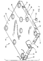
- FIG. 1 shows a modular pallet 10.
- the pallet 10 comprises a corrugated blank 12 which is initially planar but folds to form an upper deck 14 and four tubular structures 16,18,20,22 of generally rectangular cross-section which impart rigidity to the deck 14.
- the tubular structures 16,18,20,22 are retained in their tubular orientation and reinforced with plastic posts, such as the post shown exploded in Figure 5.
- the post has a female part 26 which locates within the tubular structure 16 and serves as a rigid spacer, and upper and lower male parts 28,30 which act as caps which fasten to the female part 26 to secure the tubular structure 16 and deck 14.
- Various components of the blank 12 will be described in greater detail below.
- the blank 12 has a central rectangular portion which forms the deck 14.
- the blank 12 has lateral flaps 32,34,36,38 which extend from each side of the deck 14 along hinge lines 40 pressed into the blank 12 during die-cutting.
- the flap 32 whose construction is typical comprises four rectangular panels 42,44,46,48 joined by parallel hinge lines 50 that permit the flap 32 to be folded conveniently into the tubular structure 16. During such folding, one panel 42 locates uppermost and against a lower face 49 of the deck 14 and another panel 46 locates lowermost and parallel to the lower face 49. Three posts are used to secure the tubular structure 16.
- the post 52 which is typical is mounted to the tubular structure 16 with a set of clearance holes; a large clearance hole 54 formed in the deck 14 adjacent to one hinge line; a slightly larger clearance hole 56 formed in the upper panel 42 and positioned to overlay the clearance hole 54 in the deck 14 when the tubular structure 16 is assembled; and a smaller clearance hole 58 formed in the lower panel 46 which registers vertically with the two other clearance holes 54,56 in the assembled tubular structure 16.
- a female part 60 of the post 52 locates within the tubular structure 16 between the upper and lower panels 42,46 with its upper and lower ends overlaying the clearance holes.
- An upper male part 62 fastens to the upper end portion of the female part 60 to secure the deck 14 and the upper panel 42 therebetween, and a lower male part 64 fastens to the lower end portion of the female part 60 to secure the lower panel 46 therebetween.
- the pallet 10 is adapted to be lifted with a conventional forklift.
- two panels 44,48 which are oriented perpendicular to the lower face 49 of the deck 14 when the tubular structure 16 is assembled have clearance holes dimensioned to receive the tines of a forklift.
- Two such clearance holes 66 register horizontally when the tubular structure 16 is formed to define a continuous horizontal passage through the tubular structure 16.
- Two other clearance holes 68 register during assembly of the tubular structure 16 to define another continuous horizontal passage spaced from the other passage according to the standard spacing associated with forklift tines.
- Similar clearance holes are formed in the opposing tubular structure 20 and define another pair of continuous horizontal passages that register horizontally with the passagesof the tubular structure 16, allowing the forklift tines to extend fully through the two opposing tubular structures 16,20.
- the other pair of opposing tubular structures 18,22 are formed with similar clearance holes (not specifically indicated), thereby permitting a forklift to approach the pallet 10 from all four sides.
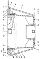
- the post 52 is further detailed in Figures 3 to 6.
- the female part 60 is shaped to receive the upper male part 62 along a central axis 70 of the female part 60 and to allow relative rotation of the upper male part 62 about the axis 70.
- the male part 62 is integrally formed with a circumferential flange 72 that butts against the upper face 74 of the deck 14 and a cylindrical sidewall 76 that extends through the clearance holes 54,56.
- the exterior of the cylindrical sidewall 76 is formed with four identical locking structures (such as the structure locking structure 78 apparent in Figures 3 and 4, structure 80 apparent in Figure 4, and structure 82 apparent in Figure 6) equally spaced circumferentially and each spanning a sector of about 20 degrees.
- the locking structure 82 which is typical, comprises three screw thread segments 84 that are parallel, vertically registered, and inclined at a common angle.
- the female part 60 comprises an upper annular shoulder 86 that locates within the clearance hole 56 in the upper panel 42, a circumferential flange 88 that butts against the upper panel 42, and an upper cylindrical sidewall 90.
- the upper sidewall 90 of the female part 60 is formed internally with four complementary locking structures (such as structures 92,94,96 apparent in Figures 3 to 6) equally spaced circumferentially and each spanning sectors of about 20 degrees.
- the locking structure of the female part 60 which is typical, comprises three screw thread segments 98 which are parallel, vertically registered, and inclined at the same common angle.
- the locking structures of the two parts 60,62 form complementary pairs which interlock simultaneously, such as the pair of locking structures 82,96 shown interlocked in Figure 6.
- the upper male part 62 can be displaced axially relative to the female part 60 through various relative axial positions until, for example, the relative axial orientation of Figure 3 is achieved.
- the deck 14 and the upper panel 42 are sandwiched between the flanges of the male and female parts 60,62 but the two parts 60,62 are not yet locked against relative axial separation.
- the upper male part 62 must still be rotated counter-clockwise (as viewed from above) about the central axis 70.
- the lower surface of the female part 60 is formed with spikes 100 that penetrate the lower panel 46 to hold the female part 60 stationary, and the upper male part 62 is formed with a central cross-bar 102.
- the upper male part 62 may be pressed further into the female part 60 in order to engage the locking structures.
- the complementary screw thread segments 98 progressively interlock in response to rotation, the upper male part 62 is drawn axially into the female part 60 thereby to better grip the upper panel 42 and the deck 14.
- An interlocked relationship between the complementary locking structures 82,96 is shown in Figure 6. In Figure 6, all three screw thread segments 84,98 associated with each of the locking structures 82,96 are engaged in the locking.
- both parts 60,62 are both formed with multiple screw thread segments, but technically the locking structures of one part may each consist of a single screw thread segment.
- the female part 60 and the upper male part 62 are formed with complementary detent structures that resist relative rotation of the parts 60,62 from the locked orientation (as shown in Figure 6) back to an unlocked orientation (as shown in Figure 3).
- the detent structures are formed on the screw thread segments of the locking structures themselves.
- the complementary pair of locking structures 82,96 shown in Figure 6 are typical.
- Upper surfaces of the screw thread segments 84 associated with the upper male part 62 are formed with sets of ratchet teeth (such as the exemplary set indicated generally with reference numeral 104) and lower surfaces of the screw thread segments 98 associated with the female part 60 are formed with complementary sets of ratchet teeth (such as the exemplary set indicated generally with reference numeral 106).
- the sets of ratchet teeth 104,106 are shaped to progressively interlock as the upper male part 62 is rotated in the counter-clockwise direction and to resist rotation in the clockwise direction. In this embodiment, the detent structures cannot be released and the parts 60,62 separated unless the corrugated blank 12 is destroyed.
- the lower male part 64 is identical to the upper male part 62, except for scale, and fastens to a lower end of the female part 60 in a similar manner.
- the lower male part 64 is once again received within the female part 60 along the central axis 70 and can be located in various relative axial positions selected to accommodate the thickness of the lower panel 46 sandwiched between the two parts 60,64.
- the female part 60 is formed internally with locking and detent structures that cooperate with corresponding components on the exterior of the lower male part 64.
- FIG. 7 An alternative post 108 appropriate for the pallet 10 of Figure 1 is illustrated in Figures 7 to 11.
- the construction of the post 108 permits convenient disassembly and removal of the post 108.
- the post 108 comprises a female part 110 together with upper and lower male parts 112,114 which have been indicated with unique reference numerals.
- Features of those parts which are similar to those of the post 52 of Figures 3 to 6 have been indicated with common reference numerals, and the description below will highlight differences in construction or function.
- the upper male part 112 has a circumferential sidewall 76 formed externally with four identical locking structures equally circumferentially spaced apart and each spanning a sector of about 20 degrees.
- the female part 110 has a circumferential sidewall 90 formed internally with four complementary locking structures equally spaced circumferentially and each spanning a sector of about 20 degrees.
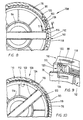
- a typical pair of complementary locking structures 116,118 is shown in Figure 11 where the locking structures 116,118 may be seen to comprise sets of parallel (horizontal) part-circular ratchet teeth shaped to interlock in a downward direction along the central axis 70 of the female part 110 but rotate relative to one another about the central axis 70.
- the interlocking is progressive and increases as axial separation of the two parts 60,62 is reduced thereby permitting the male part 62 to be locked to the female part 110 against axial separation in various selectable relative axial positions which accommodate decks or blanks of different thickness.
- a predetermined relative angular orientation as shown in Figure 7
- the four pairs of ratchet teeth are positioned to engage simultaneously as the upper male part 112 is pushed downward into the female part 110 to a locked orientation (as in Figure 8).
- the upper male part 112 is actually rotated clockwise through about 2 to 3 degrees after insertion to achieve the exact locked orientation shown in Figure 8 as explained more fully below).
- Relative rotation of the male part 62 through roughly 20 degrees counter-clockwise causes the pairs of locking structures to disengage to allow axial separation of the two parts 60,62.
- a detent mechanism 120 (most apparent in Figure 9) is provided to resist angular rotation of the upper male part 112 relative to the female part 110 between the locked and unlocked orientations.
- the detent mechanism 120 comprises a set of vertical ratchet teeth 122 formed internally on the circumferential sidewall 90 of the female part 110.
- the detent mechanism 120 comprises a complementary single tooth or pall 124 formed externally on the cylindrical sidewall 76 of the upper male part 112.
- the detent structures are positioned so that, when the male part 112 is inserted into the female part 110 and the male part 112 is then rotated clockwise through about 2 to 3 degrees, the pall 124 engages the ratchet teeth 122 (as shown in Figures 8 and 9) to resist relative rotation from the locked orientation in response to jostling or vibration.
- Manual rotation of the male part 112 through about 2 to 3 degrees counter-clockwise causes the pall 124 to disengage from the ratchet teeth 122, allowing unhindered rotation of the male part 112 through a total angle slightly greater than 20 degrees to the unlocked orientation (substantially as shown in Figure 10) and axial separation of the parts 110,112 unhindered by the detent mechanism 120.
- This post construction not only accommodates different deck thicknesses and resists loosening of parts 110,112 in response to vibration, but also permits non-destructive disassembly of the post 108.
- the lower male part 114 is identical to the upper male part 112 except for scale.
- the female part 110 is formed with internal sets of ratchet teeth (not shown) proximate to its lower end that are used to lock the lower male part 114 to the female part 110 against axial separation and with vertical ratchet teeth (not shown) constituting part of a detent mechanism used to resist rotation of the lower male part 114 between locked and unlocked orientations relative to the female part 110.
- the posts 52,108 have been described in connection with a pallet 10 comprising a corrugated folding blank 12.
- the posts 52,108 can, however, be used with a rigid upper deck formed with appropriate clearance holes to form a pallet. In such a pallet, the posts 52,108 can be used to attach a rigid lower deck formed with appropriate clearance holes.
Landscapes
- Engineering & Computer Science (AREA)
- Mechanical Engineering (AREA)
- Pallets (AREA)
- Valve Device For Special Equipments (AREA)
- Iron Core Of Rotating Electric Machines (AREA)
- Crystals, And After-Treatments Of Crystals (AREA)
- Catching Or Destruction (AREA)
Claims (9)
- Pfosten (52, 108) für eine Palettentragfläche (14), wobei der Pfosten einen männlichen Teil (62, 112), der eine axial sich erstreckende Seitenwand (76) und einen peripherischen Flansch (72) hat, und einen weiblichen Teil (60, 110) aufweist, der so ausgebildet ist, dass er den männlichen Teil aufnehmen kann, wobei der weibliche Teil (60,110) eine sich axial erstreckende Seitenwand (90) und einen peripherischen Flansch (88) aufweist, wobei der männliche Teil (62,112) sich entlang einer Längsachse (70) des weiblichen Teils (60,110) erstreckt, und weiterhin zusammenwirkende Verschlußvorrichtungen (78, 80, 82, 116; 92, 94, 96, 118) an dem männlichen Teil (62, 112) und an dem weiblichen Teil (60,110) aufweist, um den männlichen und weiblichen Teil in einer festgelegten, relatif axialen Position zu verankern und der Entriegelung zu widerstehen, und wobei die zusammenwirkenden Verschlußvorrichtungen (78, 80, 82, 116; 92, 94, 96, 118) komplementäre Paare von Verschlußstrukturen aufweisen, wobei bei jedem Paar eine Verschlußstruktur (78, 80, 82, 116) außen an der axial sich erweiternden Seitenwand (76) des männlichen Teils (62, 112) angebracht ist, und die komplementäre Verschlußstruktur (92, 94, 96, 118) an der axial sich erstreckenden Seitenwand (90) des weiblichen Teils (60, 110) innerhalb angebracht ist, dadurch gekennzeichnet, dass der männliche Teil (62, 112) in Bezug auf die Längsachse (70) des weiblichen Teils (60, 110) drehbar ist, um die relative axiale Position des männlichen und weiblichen Teils zu bestimmen, dass die Verriegelungsstrukturen (78, 80, 82, 116; 92, 94, 96, 118) jedes sich ergänzenden Paars so geformt sind, dass sie die Drehung des männlichen Teils (62, 112) in Bezug auf die Längsachse (70) ermöglichen, wodurch der männliche und weibliche Teil zwischen einer unverschlossenen Ausrichtung, in der die Verschlußstruktur eine axiale Teilung der männlichen und weiblichen Teile erlauben, und einer verschlossenen Ausrichtung, in der die Verschlußstrukturen (78, 80, 82, 116; 92, 94, 96, 118) einer axialen Trennung der männlichen und weiblichen Teile widerstehen, bewegt werden und dadurch dass Arretierungsvorrichtungen (104, 106; 120) vorgesehen sind um einer relativen Drehung der männlichen und weiblichen Teile (62, 112; 60, 110) zu widerstehen, wobei die Arrtierungsvorrichtung eine Sperrstruktur (104, 124) aufweist, die außerhalb an dem männlichen Teil (62, 112) angebracht ist, und eine komplementäre Sperrstruktur (106, 122), die innerhalb an dem weiblichen Teil (60, 110) angebracht ist.
- Pfosten (52, 108) nach Anspruch 1, wobei die Verriegelungsstrukturen (78, 80, 82, 116; 92, 94, 118) jedes sich ergänzenden Paares eine Mehrzahl vorwiegend paralleler Schraubengewindeabschnitte (84, 98) aufweisen, die an einem der männlichen und weiblichen Bauteile ausgebildet sind (62, 112; 60,110), und zumindest einen Schraubengewindeabschnitt (98, 84), der derart angeordnet ist, dass er mit der genannten Mehrzahl der Schraubengewindeabschnitte (84, 98) an dem anderen der weiblichen und männlichen Bauteile (60,110; 62,112) in Eingriff ist, und wobei die Mehrzahl der Schraubengewindeabschnitte (84, 98) und der zumindest eine Schraubengewindeabschnitt (98, 84) derartig geneigt sind, dass durch die ineinandergreifenden Schraubengewindeabschnitte eine relative Drehung der männlichen und weiblichen Bauteile (62, 112; 60, 110) in einer vorbestimmten Winkelrichtung um die Achse (70) als Folge hat, dass die ineinandergreifenden Schraubengewinde den männlichen Bauteil (62, 112) axial in den weiblichen Bauteil (60,110) ziehen.
- Pfosten nach Anspruch 2, wobei die Arretierungsvorrichtungen (104,106;120) Rastzähne (104), die an jedem der Mehrzahl der Schraubengewindeabschnitte (84) ausgebildet sind, und komplementäre Rastzähne (106) aufweisen, die an dem zumindest einen Schraubengewindeabschnitt (98) ausgebildet sind, wobei die Rastzähne (104) und die komplementären Rastzähne (106) so geformt sind, dass sie progressiv ineinander passen übereinstimmend mit der relativen Drehung der männlichen und weiblichen Bauteile (62,112;60,110) in der vorbestimmten Winkelrichtung und um sich gegen relative Drehung der männlichen und weiblichen Bauteile zu sperren, die in der entgegengesetzten Richtung der Winkelrichtung liegen.
- Pfosten nach Anspruch 1, wobei jedes komplementäre Paar der Verriegelungsstrukturen eine erste Verriegelungsstruktur (118) aufweist, die an dem weiblichen Bauteil (110) ausgebildet ist, das eine Mehrzahl von parallel verlaufenden, teilrunden Rastzähnen (118) aufweist, die senkrecht zu der Längsachse (70) verlaufen; und, eine zweite Verriegelungsstruktur (116), die auf dem männlichen Bauteil (112) ausgebildet ist, die einen Satz parallel verlaufender teilrunder Rastzähne (116) aufweist, die so geformt und ausgerichtet sind, dass sie progressiv mit den Rastzähnen (118) des weiblichen Bauteils (110) ineinandergreifen, wenn der männliche Bauteil (112) axial in das weibliche Bauteil (110) versetzt wird.
- Pfosten nach Anspruch 4, wobei die Verriegelungsstruktur (122) eines der männlichen und weiblichen Bauteile (112; 110) einen Satz Rastzähne (122) aufweist, die parallel ausgerichtet sind zu der Längsachse (70); und die Arretierungsstruktur (124) der anderen der weiblichen und männlichen Bauteile (110;112) einen Zahn (124) aufweist, der dazu ausgebildet ist, um mit dem Satz der Rastzähne (122) ineinanderzugreifen.
- Pfosten nach Anspruch 4 oder Anspruch 5, wobei jedes der Paare der Verriegelungsstrukturen (116, 118) aufgeht, wenn sie sich relativ zueinander durch einen ersten Winkel von ihrer verschlossenen Ausrichtung zu ihrer unverschlossenen Ausrichtung drehen; und die Arretierungsvorrichtungen (122, 124) sind dazu angeordnet, um außer Eingriff zu kommen, wenn die Paare der Verriegelungsstrukturen (116, 118) von ihrer verschlossenen Ausrichtung in Richtung auf ihre geöffnete Ausrichtung durch einen zweiten Winkel drehen, der kleiner als der erste Winkel ist.
- Modulpalette (10), die einen gefalteten planaren Zuschnitt (12) aufweist, der eine obere Tragfläche (14) und vier Röhrenstrukturen (16, 18, 20, 22) hat, die der Tragfläche Festigkeit verleihen, wobei jede dieser Röhrenstrukturen (16, 18, 20, 22) in ihrer röhrenförmigen Ausrichtung gehalten und verstärkt wird durch eine Mehrzahl von Pfosten (52, 108), und wobei jeder dieser Pfosten (52, 108) so ist, wie in einem der vorgenannten Ansprüche beansprucht ist.
- Modulpalette nach Anspruch 7, wobei ein Teil der oberen Tragfläche (14) zwischen dem peripherischen Flansch (72) des männlichen Bauteils (62, 112) und dem peripherischen Flansch (88) des weiblichen Bauteils (60, 110) von jedem der Pfosten (52, 108) zwischengeschoben wird.
- Modulpalette nach Anspruch 7 oder Anspruch 8, wobei jede der Röhrenstrukturen (16, 18, 20, 22) eine entsprechende seitliche Klappe (32, 34, 36, 38) aufweisen, mit einer Seite der oberen Tragfläche (14) verbunden sind und entlang einer Scharnierlinie (40) mit der genannten verbundenen Seite der oberen Tragfläche verbunden sind, wobei jede Seitenklappe (32, 34, 36, 38) eine Mehrzahl von Platten (42, 44, 46, 48) aufweist, die durch Schamierlinien (50) derart zusammengefügt sind, dass die Klappe (32, 34, 36, 38) in die Röhrenstruktur (16, 18, 20, 22) klappt, wobei eine der Platten (42) parallel verläuft zu und gegen eine der Seiten der oberen Tragfläche (14), und eine andere der Platten (46) parallel zu und räumlich entfernt von der einen Seite (49) der oberen Tragfläche (14) ist, und wobei eine Bohrung für die Aufnahme jedes der Pfosten durch ein Durchgangsloch (56) in der einen Platte (42) festgelegt ist, das mit einem Durchgangsloch (58) in der anderen Platte (46) und mit einem Durchgangsloch (54) in der oberen Tragfläche fluchtet.
Applications Claiming Priority (3)
| Application Number | Priority Date | Filing Date | Title |
|---|---|---|---|
| US08/562,561 US5603266A (en) | 1995-11-24 | 1995-11-24 | Modular pallets and components therefor |
| US562561 | 1995-11-24 | ||
| PCT/CA1996/000751 WO1997019862A2 (en) | 1995-11-24 | 1996-11-14 | Modular pallet |
Publications (2)
| Publication Number | Publication Date |
|---|---|
| EP0876285A1 EP0876285A1 (de) | 1998-11-11 |
| EP0876285B1 true EP0876285B1 (de) | 2001-07-25 |
Family
ID=24246791
Family Applications (1)
| Application Number | Title | Priority Date | Filing Date |
|---|---|---|---|
| EP96937155A Expired - Lifetime EP0876285B1 (de) | 1995-11-24 | 1996-11-14 | Modulare Palette |
Country Status (7)
| Country | Link |
|---|---|
| US (1) | US5603266A (de) |
| EP (1) | EP0876285B1 (de) |
| AT (1) | ATE203481T1 (de) |
| AU (1) | AU7488696A (de) |
| CA (1) | CA2189917C (de) |
| DE (1) | DE69614148D1 (de) |
| WO (1) | WO1997019862A2 (de) |
Families Citing this family (22)
| Publication number | Priority date | Publication date | Assignee | Title |
|---|---|---|---|---|
| WO2000071431A1 (en) * | 1999-05-19 | 2000-11-30 | Palletronix Corporation | Components for modular pallets |
| FR2798905B1 (fr) * | 1999-09-27 | 2002-03-01 | Sca Emballage France | Conteneur du type caisse-palette |
| US6837008B2 (en) * | 2000-02-09 | 2005-01-04 | University Of Florida | Device for impeding a route of travel of crawling arthropods |
| US6378242B1 (en) * | 2000-05-11 | 2002-04-30 | University Of Florida | Coaster for shielding against crawling arthropods |
| US20040226489A1 (en) * | 2002-03-28 | 2004-11-18 | Greene Joseph Paul | Interlocking modular tubular pallet |
| US20040071540A1 (en) * | 2002-10-15 | 2004-04-15 | Lucas Philip J. | Disposable/recyclable pallet system and method |
| US20050229819A1 (en) * | 2004-03-03 | 2005-10-20 | Hollander David S | Hybrid shipping pallet system |
| US7360493B2 (en) * | 2004-08-12 | 2008-04-22 | 21St Century Plastics Corporation | Modular pallet and method |
| US7779765B2 (en) | 2006-03-03 | 2010-08-24 | Daniel Kelly | Pallet with telescoped leg assemblies |
| US8656843B2 (en) * | 2006-05-18 | 2014-02-25 | Conitex-Sonoco, Llc | Pallets rails and methods for making same |
| US20070266909A1 (en) * | 2006-05-18 | 2007-11-22 | Conitex-Sonoco, Llc | Nestable Pallet |
| US20090223422A1 (en) * | 2006-05-18 | 2009-09-10 | Conitex-Sonoco, Llc | Pallets rails and methods for making same |
| US8701570B2 (en) | 2011-05-27 | 2014-04-22 | Capstone Innovations, Llc | Expandable modular interlocking pallet system |
| US8813658B2 (en) * | 2011-12-17 | 2014-08-26 | Chep Technology Pty Limited | Low friction shipping platform |
| DE102012003207A1 (de) * | 2012-02-17 | 2013-08-22 | Schoeller Arca Systems Gmbh | Mehrteilige Transportpalette |
| US9433454B2 (en) | 2013-03-14 | 2016-09-06 | Amei Technologies, Inc. | Variable angle screws, plates and systems |
| US11059623B1 (en) | 2020-02-26 | 2021-07-13 | International Business Machines Corporation | Self-locking structure for isolation damper based platforms |
| WO2022009183A1 (en) * | 2020-07-10 | 2022-01-13 | Kar-Tainer International Ltd | Modular goods-carrying system |
| IT202000022018A1 (it) * | 2020-09-18 | 2022-03-18 | Riccardo Serafin | Pallet particolarmente versatile |
| KR20260026058A (ko) * | 2023-06-16 | 2026-02-25 | 폴 장 | 압축 지지력이 증강된 복합 팔레트 및 그 제조 방법 |
| CN222474770U (zh) * | 2024-06-17 | 2025-02-14 | 微一绿色环保科技(海盐)有限公司 | 一种载物托盘 |
| CN119078994A (zh) * | 2024-10-09 | 2024-12-06 | 岚图汽车科技有限公司 | 动力总成偏置合装装置 |
Family Cites Families (15)
| Publication number | Priority date | Publication date | Assignee | Title |
|---|---|---|---|---|
| NL136319C (de) * | 1966-01-10 | |||
| US3610172A (en) * | 1969-08-21 | 1971-10-05 | Menasha Corp | Pallet construction |
| GB1362075A (en) * | 1972-01-08 | 1974-07-30 | Mardon Illingworth | Attachable leg |
| US3915099A (en) * | 1972-10-02 | 1975-10-28 | Wonder Ind Inc | Support column and disposable pallet structure |
| US3804032A (en) * | 1972-10-02 | 1974-04-16 | L Baucom | Pallet and pallet leg |
| SE437968B (sv) * | 1982-02-26 | 1985-03-25 | Lars Hammarberg | Lastpall |
| US4604014A (en) * | 1984-07-12 | 1986-08-05 | Illinois Tool Works Inc. | Pallet fastener |
| GB2172573B (en) * | 1985-03-22 | 1989-02-01 | Philip Marcel Thomas | Pallet |
| US5388533A (en) * | 1988-08-09 | 1995-02-14 | Pigott; Brandon L. | Pallet and components thereof |
| US5193464A (en) * | 1991-04-25 | 1993-03-16 | Plastic Pallet Systems, Inc. | Polymer pallet leg for a cardboard pallet base |
| US5197396A (en) * | 1991-08-05 | 1993-03-30 | Penda Corporation | Double deck plastic pallet |
| US5195440A (en) * | 1991-09-30 | 1993-03-23 | Container Corporation International Inc. | Pallet fabricated of still foldable material |
| US5367961A (en) * | 1992-10-28 | 1994-11-29 | Arai; Hiroshi | Pallet support leg including semi-circular flange blades |
| US5417167A (en) * | 1993-03-03 | 1995-05-23 | Salflex Polymers Ltd. | Plastic pallet |
| US5513577A (en) * | 1994-06-07 | 1996-05-07 | Weis; Jack E. | Adjustable pallet leg |
-
1995
- 1995-11-24 US US08/562,561 patent/US5603266A/en not_active Expired - Fee Related
-
1996
- 1996-11-08 CA CA002189917A patent/CA2189917C/en not_active Expired - Fee Related
- 1996-11-14 AT AT96937155T patent/ATE203481T1/de active
- 1996-11-14 EP EP96937155A patent/EP0876285B1/de not_active Expired - Lifetime
- 1996-11-14 WO PCT/CA1996/000751 patent/WO1997019862A2/en not_active Ceased
- 1996-11-14 AU AU74886/96A patent/AU7488696A/en not_active Abandoned
- 1996-11-14 DE DE69614148T patent/DE69614148D1/de not_active Expired - Lifetime
Also Published As
| Publication number | Publication date |
|---|---|
| DE69614148D1 (de) | 2001-08-30 |
| ATE203481T1 (de) | 2001-08-15 |
| EP0876285A1 (de) | 1998-11-11 |
| WO1997019862A3 (en) | 1997-08-28 |
| AU7488696A (en) | 1997-06-19 |
| WO1997019862A2 (en) | 1997-06-05 |
| CA2189917A1 (en) | 1997-05-25 |
| US5603266A (en) | 1997-02-18 |
| CA2189917C (en) | 2006-10-17 |
Similar Documents
| Publication | Publication Date | Title |
|---|---|---|
| EP0876285B1 (de) | Modulare Palette | |
| US5143283A (en) | Reinforced container for large objects | |
| US8365677B2 (en) | Foldably constructed force-resisting structures having interior support ribs | |
| US7007613B2 (en) | Foldable pallet with minimized use of material and having self-locking fasteners | |
| US9783333B1 (en) | Post construction and tiered palletizable container comprising such posts | |
| EP0674595B1 (de) | Transportbehälter mit selbstschliessendem oberrand | |
| US6547127B2 (en) | Tote box with multiple piece top rail including corner pieces with projections | |
| US10246219B2 (en) | Foldably constructed force-resisting structure or support | |
| CN110436014A (zh) | 组合托盘箱和托盘箱 | |
| US20070068426A1 (en) | Foldable support leg and pallet assembly formed therefrom | |
| WO2002020358A1 (en) | Tote box with corner enhancers and multiple piece top rail | |
| US3763791A (en) | Disposable pallet | |
| US5513577A (en) | Adjustable pallet leg | |
| US6305601B1 (en) | Tote box with corner enhancers and top rail | |
| US7597194B2 (en) | Shipping container with integrated pallet and reinforced wall structure | |
| US5386786A (en) | Predominantly paperboard spacer comprising interlocked beams | |
| WO2000071431A1 (en) | Components for modular pallets | |
| DE19948124A1 (de) | Zerlegbare Stapelkiste | |
| US6793085B1 (en) | High-stability composable case | |
| US12397965B1 (en) | Modular crate components and systems | |
| AU2000266968A1 (en) | High-stability composable case | |
| EP1290297A1 (de) | Bühne | |
| JP2593289Y2 (ja) | 引出し用収納枠 | |
| AU705407C (en) | Slats for furniture | |
| WO2003020603A1 (en) | Collapsible packing boxes |
Legal Events
| Date | Code | Title | Description |
|---|---|---|---|
| PUAI | Public reference made under article 153(3) epc to a published international application that has entered the european phase |
Free format text: ORIGINAL CODE: 0009012 |
|
| 17P | Request for examination filed |
Effective date: 19980828 |
|
| AK | Designated contracting states |
Kind code of ref document: A1 Designated state(s): AT BE CH DE DK ES FI FR GB GR IE IT LI LU MC NL PT SE |
|
| 17Q | First examination report despatched |
Effective date: 19990305 |
|
| GRAG | Despatch of communication of intention to grant |
Free format text: ORIGINAL CODE: EPIDOS AGRA |
|
| GRAG | Despatch of communication of intention to grant |
Free format text: ORIGINAL CODE: EPIDOS AGRA |
|
| GRAH | Despatch of communication of intention to grant a patent |
Free format text: ORIGINAL CODE: EPIDOS IGRA |
|
| GRAH | Despatch of communication of intention to grant a patent |
Free format text: ORIGINAL CODE: EPIDOS IGRA |
|
| GRAA | (expected) grant |
Free format text: ORIGINAL CODE: 0009210 |
|
| AK | Designated contracting states |
Kind code of ref document: B1 Designated state(s): AT BE CH DE DK ES FI FR GB GR IE IT LI LU MC NL PT SE |
|
| PG25 | Lapsed in a contracting state [announced via postgrant information from national office to epo] |
Ref country code: NL Free format text: LAPSE BECAUSE OF FAILURE TO SUBMIT A TRANSLATION OF THE DESCRIPTION OR TO PAY THE FEE WITHIN THE PRESCRIBED TIME-LIMIT Effective date: 20010725 Ref country code: LI Free format text: LAPSE BECAUSE OF FAILURE TO SUBMIT A TRANSLATION OF THE DESCRIPTION OR TO PAY THE FEE WITHIN THE PRESCRIBED TIME-LIMIT Effective date: 20010725 Ref country code: IT Free format text: LAPSE BECAUSE OF FAILURE TO SUBMIT A TRANSLATION OF THE DESCRIPTION OR TO PAY THE FEE WITHIN THE PRESCRIBED TIME-LIMIT;WARNING: LAPSES OF ITALIAN PATENTS WITH EFFECTIVE DATE BEFORE 2007 MAY HAVE OCCURRED AT ANY TIME BEFORE 2007. THE CORRECT EFFECTIVE DATE MAY BE DIFFERENT FROM THE ONE RECORDED. Effective date: 20010725 Ref country code: FR Free format text: LAPSE BECAUSE OF FAILURE TO SUBMIT A TRANSLATION OF THE DESCRIPTION OR TO PAY THE FEE WITHIN THE PRESCRIBED TIME-LIMIT Effective date: 20010725 Ref country code: FI Free format text: LAPSE BECAUSE OF FAILURE TO SUBMIT A TRANSLATION OF THE DESCRIPTION OR TO PAY THE FEE WITHIN THE PRESCRIBED TIME-LIMIT Effective date: 20010725 Ref country code: CH Free format text: LAPSE BECAUSE OF FAILURE TO SUBMIT A TRANSLATION OF THE DESCRIPTION OR TO PAY THE FEE WITHIN THE PRESCRIBED TIME-LIMIT Effective date: 20010725 Ref country code: BE Free format text: LAPSE BECAUSE OF FAILURE TO SUBMIT A TRANSLATION OF THE DESCRIPTION OR TO PAY THE FEE WITHIN THE PRESCRIBED TIME-LIMIT Effective date: 20010725 Ref country code: AT Free format text: LAPSE BECAUSE OF FAILURE TO SUBMIT A TRANSLATION OF THE DESCRIPTION OR TO PAY THE FEE WITHIN THE PRESCRIBED TIME-LIMIT Effective date: 20010725 |
|
| REF | Corresponds to: |
Ref document number: 203481 Country of ref document: AT Date of ref document: 20010815 Kind code of ref document: T |
|
| REG | Reference to a national code |
Ref country code: CH Ref legal event code: EP |
|
| REG | Reference to a national code |
Ref country code: IE Ref legal event code: FG4D |
|
| REF | Corresponds to: |
Ref document number: 69614148 Country of ref document: DE Date of ref document: 20010830 |
|
| PG25 | Lapsed in a contracting state [announced via postgrant information from national office to epo] |
Ref country code: SE Free format text: LAPSE BECAUSE OF FAILURE TO SUBMIT A TRANSLATION OF THE DESCRIPTION OR TO PAY THE FEE WITHIN THE PRESCRIBED TIME-LIMIT Effective date: 20011025 Ref country code: PT Free format text: LAPSE BECAUSE OF FAILURE TO SUBMIT A TRANSLATION OF THE DESCRIPTION OR TO PAY THE FEE WITHIN THE PRESCRIBED TIME-LIMIT Effective date: 20011025 Ref country code: DK Free format text: LAPSE BECAUSE OF FAILURE TO SUBMIT A TRANSLATION OF THE DESCRIPTION OR TO PAY THE FEE WITHIN THE PRESCRIBED TIME-LIMIT Effective date: 20011025 |
|
| PG25 | Lapsed in a contracting state [announced via postgrant information from national office to epo] |
Ref country code: GR Free format text: LAPSE BECAUSE OF FAILURE TO SUBMIT A TRANSLATION OF THE DESCRIPTION OR TO PAY THE FEE WITHIN THE PRESCRIBED TIME-LIMIT Effective date: 20011026 Ref country code: DE Free format text: LAPSE BECAUSE OF FAILURE TO SUBMIT A TRANSLATION OF THE DESCRIPTION OR TO PAY THE FEE WITHIN THE PRESCRIBED TIME-LIMIT Effective date: 20011026 |
|
| PG25 | Lapsed in a contracting state [announced via postgrant information from national office to epo] |
Ref country code: MC Free format text: LAPSE BECAUSE OF NON-PAYMENT OF DUE FEES Effective date: 20011114 Ref country code: LU Free format text: LAPSE BECAUSE OF NON-PAYMENT OF DUE FEES Effective date: 20011114 Ref country code: IE Free format text: LAPSE BECAUSE OF FAILURE TO SUBMIT A TRANSLATION OF THE DESCRIPTION OR TO PAY THE FEE WITHIN THE PRESCRIBED TIME-LIMIT Effective date: 20011114 Ref country code: GB Free format text: LAPSE BECAUSE OF NON-PAYMENT OF DUE FEES Effective date: 20011114 |
|
| EN | Fr: translation not filed | ||
| REG | Reference to a national code |
Ref country code: GB Ref legal event code: IF02 |
|
| NLV1 | Nl: lapsed or annulled due to failure to fulfill the requirements of art. 29p and 29m of the patents act | ||
| PG25 | Lapsed in a contracting state [announced via postgrant information from national office to epo] |
Ref country code: ES Free format text: LAPSE BECAUSE OF FAILURE TO SUBMIT A TRANSLATION OF THE DESCRIPTION OR TO PAY THE FEE WITHIN THE PRESCRIBED TIME-LIMIT Effective date: 20020131 |
|
| REG | Reference to a national code |
Ref country code: CH Ref legal event code: PL |
|
| PLBE | No opposition filed within time limit |
Free format text: ORIGINAL CODE: 0009261 |
|
| STAA | Information on the status of an ep patent application or granted ep patent |
Free format text: STATUS: NO OPPOSITION FILED WITHIN TIME LIMIT |
|
| 26N | No opposition filed | ||
| REG | Reference to a national code |
Ref country code: IE Ref legal event code: MM4A |
|
| REG | Reference to a national code |
Ref country code: HK Ref legal event code: WD Ref document number: 1017130 Country of ref document: HK |