EP0876682B1 - Vorrichtung zur detektierung von wärmestrahlung und damit ausgerüstetes anwesenheits-detektierungsgerät - Google Patents
Vorrichtung zur detektierung von wärmestrahlung und damit ausgerüstetes anwesenheits-detektierungsgerät Download PDFInfo
- Publication number
- EP0876682B1 EP0876682B1 EP97901666A EP97901666A EP0876682B1 EP 0876682 B1 EP0876682 B1 EP 0876682B1 EP 97901666 A EP97901666 A EP 97901666A EP 97901666 A EP97901666 A EP 97901666A EP 0876682 B1 EP0876682 B1 EP 0876682B1
- Authority
- EP
- European Patent Office
- Prior art keywords
- detector
- hot
- junction points
- cold
- thermocouple
- Prior art date
- Legal status (The legal status is an assumption and is not a legal conclusion. Google has not performed a legal analysis and makes no representation as to the accuracy of the status listed.)
- Expired - Lifetime
Links
Images


Classifications
-
- G—PHYSICS
- G08—SIGNALLING
- G08B—SIGNALLING SYSTEMS, e.g. PERSONAL CALLING SYSTEMS; ORDER TELEGRAPHS; ALARM SYSTEMS
- G08B13/00—Burglar, theft or intruder alarms
- G08B13/18—Actuation by interference with heat, light, or radiation of shorter wavelength; Actuation by intruding sources of heat, light, or radiation of shorter wavelength
- G08B13/189—Actuation by interference with heat, light, or radiation of shorter wavelength; Actuation by intruding sources of heat, light, or radiation of shorter wavelength using passive radiation detection systems
- G08B13/19—Actuation by interference with heat, light, or radiation of shorter wavelength; Actuation by intruding sources of heat, light, or radiation of shorter wavelength using passive radiation detection systems using infrared-radiation detection systems
- G08B13/193—Actuation by interference with heat, light, or radiation of shorter wavelength; Actuation by intruding sources of heat, light, or radiation of shorter wavelength using passive radiation detection systems using infrared-radiation detection systems using focusing means
-
- H—ELECTRICITY
- H10—SEMICONDUCTOR DEVICES; ELECTRIC SOLID-STATE DEVICES NOT OTHERWISE PROVIDED FOR
- H10N—ELECTRIC SOLID-STATE DEVICES NOT OTHERWISE PROVIDED FOR
- H10N10/00—Thermoelectric devices comprising a junction of dissimilar materials, i.e. devices exhibiting Seebeck or Peltier effects
- H10N10/80—Constructional details
- H10N10/81—Structural details of the junction
- H10N10/817—Structural details of the junction the junction being non-separable, e.g. being cemented, sintered or soldered
-
- Y—GENERAL TAGGING OF NEW TECHNOLOGICAL DEVELOPMENTS; GENERAL TAGGING OF CROSS-SECTIONAL TECHNOLOGIES SPANNING OVER SEVERAL SECTIONS OF THE IPC; TECHNICAL SUBJECTS COVERED BY FORMER USPC CROSS-REFERENCE ART COLLECTIONS [XRACs] AND DIGESTS
- Y10—TECHNICAL SUBJECTS COVERED BY FORMER USPC
- Y10S—TECHNICAL SUBJECTS COVERED BY FORMER USPC CROSS-REFERENCE ART COLLECTIONS [XRACs] AND DIGESTS
- Y10S250/00—Radiant energy
- Y10S250/01—Passive intrusion detectors
Definitions
- the present invention relates to a radiation detection device thermal and a presence detection device based on such a device.
- the invention can be used in particular, but not exclusively, for the detection of an intrusion into the surveillance of security zones.
- Sealing systems are generally inadequate by the fact that the most are usable only once and are unable to afford the remote monitoring.
- pyroelectric and semiconductor devices are generally used for the detection of thermal radiation emitted by a moving source.
- the thermal radiation emitted varies with the emissivity of on the surface, these detectors have the great disadvantage of having their responsiveness dependent on the wavelength. It is therefore necessary to choose the detector in function of the source to be monitored since it works in a frequency band narrow.
- these types of detectors heat up with the radiation they always receive and require a cooling system.
- thermopile in shape cylindrical extending parallel to the incident light to be measured and arranged so that its cylindrical face is not exposed to this incident light.
- the cylindrical face comprises, near a flat face for receiving the light, hot junctions and, near the second flat face, cold junctions.
- the thermopile is attached to a support at the second flat face via thermal conductive adhesive.
- An object of the present invention is to provide a device for detection of thermal radiation which does not suffer from the aforementioned drawbacks.
- a reflector type concentrator with a detector of the aforementioned type makes it possible to pinpoint a surveillance zone with precision and detect any change in the state of thermal imbalance in the area monitored.
- the detector responds to a small difference of temperature representative of the difference between the energies absorbed and transformed into heat flux under exposed regions and under non-exposed regions exposed.
- the concentrator is a parabolic reflector.
- the detector is mounted movable by relative to an axis of the concentrator to allow easy adaptation to the field of detection by simple position adjustment.
- the use of a concentrator advantageously replaces the use of an optical lens to focus the incident thermal rays, and thus avoids losses by transmission or by capacitive effect of the material of the lens.
- the operating principle and manufacturing technology of the detector allow to dispense with conventional cooling problems which require expensive and expensive cryostats or Peltier devices in energy.
- the detector is sensitive to any object, even at very low temperatures, emitting by thermal radiation in a very wide band extending from 0.75 at 1000 micrometers, that is between the visible and the microwaves. It provides information representative of instantaneous imbalance variations energy between a system and its environment, and thus function as variable speed thermal flowmeter.
- the detector is composed of at least a pair of planar thermocouple elements having a cold junction in contact thermal with a protected portion of the detector and at least one hot junction in thermal contact with an exposed portion of the detector.
- the exposed portion (s) and the protected portion (s) may constitute a common active surface of the detector, being respectively formed by substantially absorbent surface elements and by substantially reflective surface elements relative to radiation thermal.
- the detector comprises a plurality of thermocouple elements mounted in series and arranged in several lines connected at the ends so as to form a meandering path, the cold and hot junctions being arranged in rows respective alternate arranged transversely to the lines and being in contact thermal with a material which presents the sensitive surface in the form of strips reflective and absorbent arranged in alternating rows in phase and aligned respectively with cold and hot junctions.
- thermocouple elements are produced by alternating elements of copper and constantan deposited on a material substrate electrically insulating, such as the material known under the name "Kapton” which is a registered trademark of the Dupont de Nemours Company, and the elements thermocouples are covered with a material that is substantially transparent to the thermal radiation, which can also be Kapton, the portions of the material covering a cold junction being coated with a layer of material reflective.
- the reflective parts can be obtained by depositing gold on the surface of the material covering the thermocouples.
- the layer of isothermal material is a layer metal intended to be brought into contact with a mechanical support surface.
- the invention also relates to a presence detection device.
- a presence detection device comprising at least one type of thermal radiation detection device mentioned above, and a control means receiving the detection signal (s) and emitting a signal indicative of presence based on the signal (s) detection.
- FIG. 1 shows a detection assembly 10 composed of a parabolic reflector 12 and a thermal radiation detector 14.
- the detector has an active surface maintained opposite the reflector thanks to a support structure 16.
- the reflector 12 is held securely around its circumference by a casing 18.
- the support structure comprises a first rod 20 secured at one end to the casing and extending parallel to the axis main A-A 'of the reflector 12 in the direction of its flaring.
- a second rod 22 is slidably mounted on the first rod 20 and in square to it.
- This second rod 22 is finished, towards its free end, by a square portion 22a aligned with the main axis A-A ' of the reflector 12.
- the free end of the portion 22a of this second rod 22 has a support surface 24 for the detector 14, thus making it possible to position the latter at a determined point relative to the reflector - by example its focus - by sliding the second rod 22 along the first rod 20.
- the detection assembly is fixed on a base by means of fixing lugs 26 which depend on the housing 18.
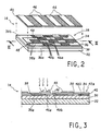
- FIGS 2 and 3 show in detail the thermal radiation detector 14 used in the detection assembly but in simplified form, in particular in regarding the number of active elements.
- Detector 14 includes a substrate 30 of flexible material, such as "Kapton", of a thickness comprised substantially between 20 and 60 micrometers.
- the surface 30a of the substrate intended to be turned towards the detector support 24 includes a deposit of isothermal material 32, by example a metal such as copper, with a thickness substantially between 20 and 100 micrometers.
- the other surface 30b of the substrate 30 comprises a succession of elements thermocouples 34, 36 forming a continuous track 38.
- the track is configured under the shape of several parallel main lines about 5 mm long and 0.5 mm wide, connected at the ends so as to form a continuous path in meanders from one end to the other of the track.
- Runway 38 is made up of a deposit of copper coated constantan on short successive portions 38a discontinuous. Each copper / constantan interface on the surface of runway 38 creates a planar thermocouple junction 40a, 40b.
- thermocouple junctions 40a, 40b are arranged in perpendicular rows to the main lines of it.
- Track 38 is covered with a film 42 with a thickness of 5 to 25 micrometers of material substantially transparent to thermal radiation and electrically insulating, such as Kapton.
- the film 42 is coated, on surface portions above the junctions intended to define cold junctions 40a, of a deposit of material reflective 44, for example a layer of gold with a thickness between 0.1 and 5 micrometers.
- the reflective material 44 comprises a series of strips spanning alternating rows of junctions.
- the surfaces 46 of the film 42 no coated with reflective material 44 constitute the surface portions absorbent, located in a complementary manner above the junctions intended to define hot junctions 40b.
- These surface portions 46 can be possibly covered with a material with high absorption of radiation thermal, such as black paint.
- the film can be produced in Kapton of the "special black body" type, marketed by the company DuPont de Nemours.
- thermocouple junction elements 34, 36 When the active surface 42a of the detector 14 receives radiation due to the appearance of a heat source, such as a person, parts 46 of film 42 not coated with reflective material 44 undergo a higher temperature increase than parts coated with material reflective. A temperature differential is thus formed on the active surface of the detector, which will be transmitted to the underlying thermocouple junction elements 34, 36. Thus, an alternation of cold and hot junctions 40a, 40b is obtained. along runway 38 of junctions. Each pair of cold and hot junctions adjacent 40a, 40b produces an electromotive force according to the Seebeck effect. We then obtains a succession of elementary stacks in series along the track 38, delivering a detection signal in the form of a potential difference between the two ends of the track 38.
- Ohmic contacts 48 soldered to these two ends allow the detection signal to be collected. This signal is proportional to the temperature differential created in response to radiation thermal concentrated by the reflector 12 on the active surface of the detector 14. It is therefore representative of the heat flux received on the active surface 42a of the detector 14.
- the detector 14 can be easily produced by a person skilled in the art using printed circuit technology.
- the device is extremely flat, the thickness being less than 0.2 mm, rectangular or square, or even circular, over an area typically between 0.25 and 1 cm 2 . It typically comprises 150 to 200 thermoelectric junctions in series, but the manufacturing technology makes it possible to produce a much greater number of junctions on the same substrate.
- a detector of the type described offers a typical sensitivity between 1.5 and 2.0 microVm 2 / W and has a very low internal electrical resistance, of the order of 200 Ohms. This last characteristic allows significant amplification of the signal, by a factor of 1,000 to 10,000, or even more depending on the application, without being bothered by its own noise.
- the detector In radiation detection mode, the detector has a constant of time around 100 ms.
- the manufacturing technology and the choice of constituent materials of the detector allow use at ambient temperatures up to 250 ° C by contact.
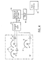
- Figure 4 is a block diagram of an example of a monitoring carried out from the detection assembly 10 of FIG. 1.
- each set has a well-defined detection field which corresponds to a surveillance zone specific.
- the detection field is adapted to the surveillance zone required in playing on one or more of the following parameters: the shape of the reflector 12, the size of the latter, the distance between the detection assembly and the base of the area the orientation of the reflector in the surveillance zone, and possibly the position of the sensitive surface of the detector 14 relative to its reflector 12.
- the shape of the reflector 12 the size of the latter
- the distance between the detection assembly and the base of the area the orientation of the reflector in the surveillance zone and possibly the position of the sensitive surface of the detector 14 relative to its reflector 12.
- the base of the cone which defines the detection surface, can be easily modulated to obtain circular or oval contours of different dimensions by varying only the distance and orientation of the reflector relative to this detection surface.
- the output signal of each detection set is transmitted to a stage respective preamplifier 52 whose gain is adjustable over a range between about 100 to 10,000.
- the preamplified signal can be optionally processed by filtering, clipping or digitization units (represented globally by reference 54) depending on the nature of the surveillance.
- the signals after preamplification and possible processing are collected on respective channels 56 of a detector 58 of amplitude variation rate (dV / dt) of the signal.
- the detector is associated with a calculation unit 60 programmed for identify the forms of analyzed signals corresponding to an intrusion. When one of these conditions is detected, the computing unit 60 sends a signal detection to an alarm station 62, possibly with data indicative of the area concerned and the nature of the intrusion.
- FIG. 5 is an example of recording, in the form of a graph, of signals collected by the detection assembly according to FIG. 1 installed in a corridor monitored.
- the ordinate represents the magnitude of the output signal, expressed in relative values, and the abscissa represents the timescale.
- the detector In an idle situation, the detector emits a floor signal presenting relatively small fluctuations. During an intrusion by a presence human, a high amplitude peak is obtained.
- the report shows respective detection peaks for a person entering the detection zone by performing a jump (peak A), a normal passage (pic B) and an entry on tiptoe (pic C).
- the signal obtained is easily detectable in all these cases thanks to the rapid detector response time and the very high sensitivity allowed by the combination of the sensor and its concentrator of the thinking type. It is possible to envisage signal discrimination at level of the calculation unit 60 making it possible to provide information on the displacement in space and time in the monitored area, as well as the number of people present.
- the detection system provides a detection signal caused by a modification, at detector 14, of the heat balance between the radiation received and the radiation re-emitted.
- the presence of an intruder in the field of detection constitutes a modification of the thermal mapping of the area monitored, either by the provision of heat (most likely), or by the masking of a heat source, which may be the case in an industrial site. Since it is almost impossible to know the temperature of each point on the surface hidden by the intruder, and that the temperature of the intruder must be equal to the average temperature of the surface it hides so that the balance remains stable, it is extremely difficult to defraud a system of surveillance based on devices according to the present invention.
- the invention lends itself to numerous variants both at the level of the detector of thermal radiation than at the concentrator.
- the concentrator can be of complex shape, studied so that the field detection is modeled on a specific contour perimeter.
- We can in particular to use computer-aided design tools for this purpose running on software for analyzing optical ray traces.
Landscapes
- Physics & Mathematics (AREA)
- General Physics & Mathematics (AREA)
- Photometry And Measurement Of Optical Pulse Characteristics (AREA)
- Geophysics And Detection Of Objects (AREA)
- Investigating Or Analyzing Materials Using Thermal Means (AREA)
- Radiation Pyrometers (AREA)
- Solid State Image Pick-Up Elements (AREA)
- Burglar Alarm Systems (AREA)
Claims (12)
- Vorrichtung zum Detektieren von Wärmestrahlung,
dadurch gekennzeichnet, dass sie umfasst:einen Detektor (14) mit einem Substrat (30), welches auf einer ersten Seite (30b) ein oder mehrere Thermopaarverbindungen, als "heiße" (40b) bezeichnet, aufweist, die dazu dienen, einer Wärmestrahlung ausgesetzt zu werden, und ein oder mehrere Thermopaaverbindungen, als "kalte" (40b) bezeichnet, aufweist, die dazu dienen, von der Wärmestrahlung geschützt zu werden, wobei der Detektor auf eine Temperaturdifferenz zwischen heißen und kalten Verbindungen anspricht, undeinen Konzentrator vom Reflektortyp (12) welcher dem Detektor zugeordnet ist, um auf diesen die Wärmestrahlung zu konzentrieren, die aus einer vorbestimmten Raumzone kommt,und dass die zweite Seite (30a) des Substrats, die der ersten Seite abgewandt ist, sich in Berührung mit einer isothermen Materialschicht (32) befindet, die sich gegenüber den heißen und kalten Verbindungen erstreckt. - Vorrichtung nach Anspruch 1,
dadurch gekennzeichnet, dass sie außerdem einen Detektor für Amplitudenänderung (dV/dt) des von dem Detektor erfassten Signals aufweist, der dazu ausgelegt ist, ein Detektorsignal der Vorrichtung zu liefern. - Vorrichtung (10) nach Anspruch 1,
dadurch gekennzeichnet, dass sie außerdem eine Analyseeinrichtung für das von dem Amplitudenänderungsdetektor ausgegebene Signal aufweist. - Vorrichtung nach einem der Ansprüche 1 bis 3,
dadurch gekennzeichnet, dass der Detektor (14) sich aus mindestens einem Paar planarer Thermopaarelemente (34, 36) zusammensetzt, welche die eine oder die mehreren heißen und kalten Verbindungen aufweisen. - Vorrichtung nach einem der Ansprüche 1 bis 4,
dadurch gekennzeichnet, dass der Detektor (14) außerdem auf den heißen Verbindungen (40b) im Wesentlichen absorbierende Oberflächenelemente aufweist, und auf den kalten Verbindungen (40a) im Wesentlichen reflektierende Oberflächenelemente (44) aufweist. - Vorrichtung nach Anspruch 5,
dadurch gekennzeichnet, dass der Detektor (14) außerdem eine Mehrzahl von Thermopaarelementen (34, 36) aufweist, die in Reihe und in mehreren Linien angeordnet sind, welche an ihren Enden derart miteinander verbunden sind, dass sie eine Mäanderbahn (38) bilden, wobei die kalten und die heißen Verbindungen (40a, 40b) an alternierenden Plätzen in Querrichtung der Linien angeordnet sind und sich in Wärmekontakt mit einem Film (42) zu befinden, der reflektierende Bänder (44) und absorbierende Bänder (46) trägt, die an alternierenden Phasenplätzen angeordnet sind und mit den kalten Verbindungen (40a) bzw. heißen Verbindungen (40b) fluchten. - Vorrichtung nach Anspruch 5 oder 6,
dadurch gekennzeichnet, dass die paarweisen Elemente von Thermopaaren (34, 36) durch abwechselnde Elemente aus Kupfer und Konstantan gebildet sind, angeordnet auf dem Substrat (30) aus elektrisch isolierendem und thermisch stark absorbierendem Material, und dass die Thermopaarelemente mit einem Material (42) bedeckt sind, welches eine erhöhte Wärmeabsorption aufweist, wobei die Materialbereiche, die eine kalte Verbindung (40a) bedecken,mit einer reflektierenden Materialschicht (44) bedeckt sind. - Vorrichtung nach Anspruch 7,
dadurch gekennzeichnet, dass das Substrat (30) aus Kapton besteht und dass das die paarweisen Thermopaarelemente (34, 36) bedeckende Material (42) aus Kapton besteht und an den reflektierenden Oberflächenbereichen (44) mit Gold bedeckt ist. - Vorrichtung nach einem der Ansprüche 1 bis 8,
dadurch gekennzeichnet, dass die isotherme Materialschicht eine Metallschicht (32) ist. - Vorrichtung nach einem der Ansprüche 1 bis 9,
dadurch gekennzeichnet, dass der Reflektor (12) parabolisch ausgebildet ist. - Vorrichtung nach einem der Ansprüche 1 bis 10,
dadurch gekennzeichnet, dass sie einen Träger (16) für den Detektor (14) aufweist, der entlang einer in Bezug auf den Reflektor festgelegten Achse (A - A') beweglich gelagert ist. - Anwesenheitsdetektor-Vorrichtung mit mindestens einer Vorrichtung zum Detektieren von Wärmestrahlung (10) nach einem der Ansprüche 1 bis 11, und mit einer Steuereinrichtung (54, 60), die das Detektorsignal oder die Detektorsignale empfängt und ein als Funktion des oder der Detektorsignale für ein Vorhandensein kennzeichnendes Signal abgibt.
Applications Claiming Priority (3)
| Application Number | Priority Date | Filing Date | Title |
|---|---|---|---|
| LU88704A LU88704A1 (fr) | 1996-01-26 | 1996-01-26 | Dispositif de détection de rayonnement thermique et appareil de détection de présence à base d'un tel dispositif |
| LU88704 | 1996-01-26 | ||
| PCT/FR1997/000142 WO1997027634A1 (fr) | 1996-01-26 | 1997-01-24 | Dispositif de detection de rayonnement thermique et appareil de detection de presence a base d'un tel dispositif |
Publications (2)
| Publication Number | Publication Date |
|---|---|
| EP0876682A1 EP0876682A1 (de) | 1998-11-11 |
| EP0876682B1 true EP0876682B1 (de) | 2002-10-23 |
Family
ID=19731576
Family Applications (1)
| Application Number | Title | Priority Date | Filing Date |
|---|---|---|---|
| EP97901666A Expired - Lifetime EP0876682B1 (de) | 1996-01-26 | 1997-01-24 | Vorrichtung zur detektierung von wärmestrahlung und damit ausgerüstetes anwesenheits-detektierungsgerät |
Country Status (9)
| Country | Link |
|---|---|
| US (1) | US6204502B1 (de) |
| EP (1) | EP0876682B1 (de) |
| JP (1) | JP2000516736A (de) |
| AT (1) | ATE226761T1 (de) |
| CA (1) | CA2244153A1 (de) |
| DE (1) | DE69716579D1 (de) |
| LU (1) | LU88704A1 (de) |
| NO (1) | NO983428L (de) |
| WO (1) | WO1997027634A1 (de) |
Families Citing this family (10)
| Publication number | Priority date | Publication date | Assignee | Title |
|---|---|---|---|---|
| ITTO980111A1 (it) * | 1998-02-12 | 1999-08-12 | Elkron Spa | Lente per la focalizzazione di radiazione infrarossa e procedimento per la sua realizzazione |
| NL1012709C2 (nl) * | 1999-07-26 | 2001-02-01 | Berkin Bv | Werkwijze voor het vervaardigen van een thermozuil op een elektrisch isolerende drager. |
| FR2832798B1 (fr) * | 2001-11-27 | 2004-01-30 | Captec | Comparateur de flux thermiques |
| JP4373695B2 (ja) * | 2003-04-16 | 2009-11-25 | 浜松ホトニクス株式会社 | 裏面照射型光検出装置の製造方法 |
| WO2006003798A1 (ja) * | 2004-07-01 | 2006-01-12 | Ulvac, Inc. | 基板温度測定装置及び処理装置 |
| JP2008060488A (ja) * | 2006-09-04 | 2008-03-13 | Kansai Paint Co Ltd | 片面電極型熱電変換モジュール |
| JP5135011B2 (ja) * | 2008-03-18 | 2013-01-30 | 沖電気防災株式会社 | 熱電変換温度センサおよびその製造方法 |
| KR101249292B1 (ko) * | 2008-11-26 | 2013-04-01 | 한국전자통신연구원 | 열전소자, 열전소자 모듈, 및 그 열전 소자의 형성 방법 |
| US9377365B2 (en) * | 2013-04-22 | 2016-06-28 | Excelitas Technologies Singapore Pte. Ltd. | Thermal sensor module with lens array |
| US10018510B2 (en) | 2013-04-22 | 2018-07-10 | Excelitas Technologies Singapore Pte. Ltd. | Motion and presence detector |
Family Cites Families (6)
| Publication number | Priority date | Publication date | Assignee | Title |
|---|---|---|---|---|
| DE1566748C2 (de) * | 1967-11-17 | 1971-07-29 | Thrings Advanced Developments | Feueralarmvorrichtung |
| CH599642A5 (de) * | 1976-11-15 | 1978-05-31 | Cerberus Ag | |
| JPS58171873A (ja) | 1982-04-02 | 1983-10-08 | Showa Denko Kk | サ−モパイルの製造方法 |
| US5045123A (en) | 1988-05-17 | 1991-09-03 | Kabushiki Kaisha Toshiba | Thermopile |
| JPH0382988A (ja) * | 1989-08-25 | 1991-04-08 | Omron Corp | 赤外線放出物体センサ装置 |
| US5059543A (en) | 1990-09-21 | 1991-10-22 | The Board Of Regents Acting For And On Behalf Of The University Of Michigan | Method of manufacturing thermopile infrared detector |
-
1996
- 1996-01-26 LU LU88704A patent/LU88704A1/fr unknown
-
1997
- 1997-01-24 US US09/117,041 patent/US6204502B1/en not_active Expired - Fee Related
- 1997-01-24 DE DE69716579T patent/DE69716579D1/de not_active Expired - Lifetime
- 1997-01-24 AT AT97901666T patent/ATE226761T1/de not_active IP Right Cessation
- 1997-01-24 WO PCT/FR1997/000142 patent/WO1997027634A1/fr not_active Ceased
- 1997-01-24 CA CA002244153A patent/CA2244153A1/en not_active Abandoned
- 1997-01-24 EP EP97901666A patent/EP0876682B1/de not_active Expired - Lifetime
- 1997-01-24 JP JP09526612A patent/JP2000516736A/ja active Pending
-
1998
- 1998-07-24 NO NO983428A patent/NO983428L/no not_active Application Discontinuation
Also Published As
| Publication number | Publication date |
|---|---|
| EP0876682A1 (de) | 1998-11-11 |
| CA2244153A1 (en) | 1997-07-31 |
| DE69716579D1 (de) | 2002-11-28 |
| ATE226761T1 (de) | 2002-11-15 |
| LU88704A1 (fr) | 1997-07-26 |
| NO983428L (no) | 1998-09-24 |
| US6204502B1 (en) | 2001-03-20 |
| NO983428D0 (no) | 1998-07-24 |
| WO1997027634A1 (fr) | 1997-07-31 |
| JP2000516736A (ja) | 2000-12-12 |
Similar Documents
| Publication | Publication Date | Title |
|---|---|---|
| JP3895474B2 (ja) | サブミリ波で機能する撮像システム | |
| US5045702A (en) | Infrared intrustion detector | |
| EP2700922B1 (de) | Bolometrischer Detektor einer elektromagnetischen Strahlung im Terahertzbereich, und Vorrichtung zur Matrixerkennung, die mit solchen Detektoren ausgestattet ist | |
| US4792682A (en) | Pyroelectric infrared temperature compensated detector | |
| FR2999803A1 (fr) | Dispositif de detection infrarouge | |
| FR2735574A1 (fr) | Dispositif de detection bolometrique pour ondes millimetriques et submillimetriques et procede de fabrication de ce dispositif | |
| LU88704A1 (fr) | Dispositif de détection de rayonnement thermique et appareil de détection de présence à base d'un tel dispositif | |
| US6034371A (en) | Semi-opaque chopper for thermal imaging system and method | |
| EP1953511A2 (de) | Thermische Bildwandlermatrix mit optischem Leseverfahren | |
| US5952661A (en) | Chopper for thermal imaging system and method | |
| US2981913A (en) | Selective infra-red detectors | |
| EP3973259A1 (de) | Vorrichtung zum aussenden und steuern von infrarotlicht und gassensor mit einer solchen vorrichtung | |
| US3535523A (en) | Radiant flux measuring apparatus of the thermopile type | |
| JPH027193B2 (de) | ||
| EP2711686B1 (de) | Optischer Detektor eines Gases | |
| FR2684763A1 (fr) | Dispostif integre de detection et d'identification d'obstacles embarque notamment a bord d'un vehicule automobile. | |
| US3792275A (en) | Infrared intrusion sensor | |
| JPH0249124A (ja) | サーモパイル | |
| US3453434A (en) | Infrared ray detector utilizing ferroelectric single crystal | |
| FR2512591A1 (fr) | Detecteur de rayonnement, notamment de rayonnement infrarouge | |
| WO2019158768A1 (en) | Gas sensor with thermopile | |
| Abdullah et al. | Device architecture for metasurface integrated uncooled SixGeyO1-xy infrared microbolometers | |
| JPH09218086A (ja) | 赤外線センサ | |
| FR2688889A1 (fr) | Dispositif de mesure de la vitesse de deplacement d'un objet. | |
| FR2727215A1 (fr) | Dispositif de veille panoramique infrarouge statique a detecteurs matriciels multiples |
Legal Events
| Date | Code | Title | Description |
|---|---|---|---|
| PUAI | Public reference made under article 153(3) epc to a published international application that has entered the european phase |
Free format text: ORIGINAL CODE: 0009012 |
|
| 17P | Request for examination filed |
Effective date: 19980727 |
|
| AK | Designated contracting states |
Kind code of ref document: A1 Designated state(s): AT BE CH DE DK ES FI FR GB GR IE IT LI LU MC NL PT SE |
|
| AX | Request for extension of the european patent |
Free format text: LT PAYMENT 980724;LV PAYMENT 980724;SI PAYMENT 980724 |
|
| 17Q | First examination report despatched |
Effective date: 19990303 |
|
| GRAG | Despatch of communication of intention to grant |
Free format text: ORIGINAL CODE: EPIDOS AGRA |
|
| GRAG | Despatch of communication of intention to grant |
Free format text: ORIGINAL CODE: EPIDOS AGRA |
|
| GRAH | Despatch of communication of intention to grant a patent |
Free format text: ORIGINAL CODE: EPIDOS IGRA |
|
| GRAH | Despatch of communication of intention to grant a patent |
Free format text: ORIGINAL CODE: EPIDOS IGRA |
|
| GRAA | (expected) grant |
Free format text: ORIGINAL CODE: 0009210 |
|
| AK | Designated contracting states |
Kind code of ref document: B1 Designated state(s): AT BE CH DE DK ES FI FR GB GR IE IT LI LU MC NL PT SE |
|
| AX | Request for extension of the european patent |
Free format text: LT PAYMENT 19980724;LV PAYMENT 19980724;SI PAYMENT 19980724 |
|
| PG25 | Lapsed in a contracting state [announced via postgrant information from national office to epo] |
Ref country code: NL Free format text: LAPSE BECAUSE OF FAILURE TO SUBMIT A TRANSLATION OF THE DESCRIPTION OR TO PAY THE FEE WITHIN THE PRESCRIBED TIME-LIMIT Effective date: 20021023 Ref country code: IT Free format text: LAPSE BECAUSE OF FAILURE TO SUBMIT A TRANSLATION OF THE DESCRIPTION OR TO PAY THE FEE WITHIN THE PRE;WARNING: LAPSES OF ITALIAN PATENTS WITH EFFECTIVE DATE BEFORE 2007 MAY HAVE OCCURRED AT ANY TIME BEFORE 2007. THE CORRECT EFFECTIVE DATE MAY BE DIFFERENT FROM THE ONE RECORDED.SCRIBED TIME-LIMIT Effective date: 20021023 Ref country code: IE Free format text: LAPSE BECAUSE OF FAILURE TO SUBMIT A TRANSLATION OF THE DESCRIPTION OR TO PAY THE FEE WITHIN THE PRESCRIBED TIME-LIMIT Effective date: 20021023 Ref country code: GR Free format text: LAPSE BECAUSE OF FAILURE TO SUBMIT A TRANSLATION OF THE DESCRIPTION OR TO PAY THE FEE WITHIN THE PRESCRIBED TIME-LIMIT Effective date: 20021023 Ref country code: GB Free format text: LAPSE BECAUSE OF FAILURE TO SUBMIT A TRANSLATION OF THE DESCRIPTION OR TO PAY THE FEE WITHIN THE PRESCRIBED TIME-LIMIT Effective date: 20021023 Ref country code: FI Free format text: LAPSE BECAUSE OF FAILURE TO SUBMIT A TRANSLATION OF THE DESCRIPTION OR TO PAY THE FEE WITHIN THE PRESCRIBED TIME-LIMIT Effective date: 20021023 Ref country code: AT Free format text: LAPSE BECAUSE OF FAILURE TO SUBMIT A TRANSLATION OF THE DESCRIPTION OR TO PAY THE FEE WITHIN THE PRESCRIBED TIME-LIMIT Effective date: 20021023 |
|
| REF | Corresponds to: |
Ref document number: 226761 Country of ref document: AT Date of ref document: 20021115 Kind code of ref document: T |
|
| REG | Reference to a national code |
Ref country code: GB Ref legal event code: FG4D Free format text: NOT ENGLISH |
|
| REG | Reference to a national code |
Ref country code: CH Ref legal event code: EP |
|
| REG | Reference to a national code |
Ref country code: IE Ref legal event code: FG4D Free format text: FRENCH |
|
| REF | Corresponds to: |
Ref document number: 69716579 Country of ref document: DE Date of ref document: 20021128 |
|
| PG25 | Lapsed in a contracting state [announced via postgrant information from national office to epo] |
Ref country code: SE Free format text: LAPSE BECAUSE OF FAILURE TO SUBMIT A TRANSLATION OF THE DESCRIPTION OR TO PAY THE FEE WITHIN THE PRESCRIBED TIME-LIMIT Effective date: 20030123 Ref country code: PT Free format text: LAPSE BECAUSE OF FAILURE TO SUBMIT A TRANSLATION OF THE DESCRIPTION OR TO PAY THE FEE WITHIN THE PRESCRIBED TIME-LIMIT Effective date: 20030123 Ref country code: DK Free format text: LAPSE BECAUSE OF FAILURE TO SUBMIT A TRANSLATION OF THE DESCRIPTION OR TO PAY THE FEE WITHIN THE PRESCRIBED TIME-LIMIT Effective date: 20030123 |
|
| PG25 | Lapsed in a contracting state [announced via postgrant information from national office to epo] |
Ref country code: LU Free format text: LAPSE BECAUSE OF NON-PAYMENT OF DUE FEES Effective date: 20030124 Ref country code: DE Free format text: LAPSE BECAUSE OF FAILURE TO SUBMIT A TRANSLATION OF THE DESCRIPTION OR TO PAY THE FEE WITHIN THE PRESCRIBED TIME-LIMIT Effective date: 20030124 |
|
| PG25 | Lapsed in a contracting state [announced via postgrant information from national office to epo] |
Ref country code: MC Free format text: LAPSE BECAUSE OF NON-PAYMENT OF DUE FEES Effective date: 20030131 Ref country code: LI Free format text: LAPSE BECAUSE OF NON-PAYMENT OF DUE FEES Effective date: 20030131 Ref country code: CH Free format text: LAPSE BECAUSE OF NON-PAYMENT OF DUE FEES Effective date: 20030131 Ref country code: BE Free format text: LAPSE BECAUSE OF NON-PAYMENT OF DUE FEES Effective date: 20030131 |
|
| LTIE | Lt: invalidation of european patent or patent extension |
Effective date: 20021023 |
|
| NLV1 | Nl: lapsed or annulled due to failure to fulfill the requirements of art. 29p and 29m of the patents act | ||
| GBV | Gb: ep patent (uk) treated as always having been void in accordance with gb section 77(7)/1977 [no translation filed] |
Effective date: 20021023 |
|
| PG25 | Lapsed in a contracting state [announced via postgrant information from national office to epo] |
Ref country code: ES Free format text: LAPSE BECAUSE OF FAILURE TO SUBMIT A TRANSLATION OF THE DESCRIPTION OR TO PAY THE FEE WITHIN THE PRESCRIBED TIME-LIMIT Effective date: 20030429 |
|
| REG | Reference to a national code |
Ref country code: IE Ref legal event code: FD4D Ref document number: 0876682E Country of ref document: IE |
|
| PLBE | No opposition filed within time limit |
Free format text: ORIGINAL CODE: 0009261 |
|
| STAA | Information on the status of an ep patent application or granted ep patent |
Free format text: STATUS: NO OPPOSITION FILED WITHIN TIME LIMIT |
|
| REG | Reference to a national code |
Ref country code: CH Ref legal event code: PL |
|
| PG25 | Lapsed in a contracting state [announced via postgrant information from national office to epo] |
Ref country code: FR Free format text: LAPSE BECAUSE OF NON-PAYMENT OF DUE FEES Effective date: 20030930 |
|
| 26N | No opposition filed |
Effective date: 20030724 |
|
| REG | Reference to a national code |
Ref country code: FR Ref legal event code: ST |