EP0876701B1 - Bordnetz eines kraftfahrzeuges - Google Patents
Bordnetz eines kraftfahrzeuges Download PDFInfo
- Publication number
- EP0876701B1 EP0876701B1 EP97901557A EP97901557A EP0876701B1 EP 0876701 B1 EP0876701 B1 EP 0876701B1 EP 97901557 A EP97901557 A EP 97901557A EP 97901557 A EP97901557 A EP 97901557A EP 0876701 B1 EP0876701 B1 EP 0876701B1
- Authority
- EP
- European Patent Office
- Prior art keywords
- power input
- voltage
- line
- input
- signal input
- Prior art date
- Legal status (The legal status is an assumption and is not a legal conclusion. Google has not performed a legal analysis and makes no representation as to the accuracy of the status listed.)
- Expired - Lifetime
Links
Images
Classifications
-
- H—ELECTRICITY
- H02—GENERATION; CONVERSION OR DISTRIBUTION OF ELECTRIC POWER
- H02J—ELECTRIC POWER NETWORKS; CIRCUIT ARRANGEMENTS OR SYSTEMS FOR SUPPLYING OR DISTRIBUTING ELECTRIC POWER; SYSTEMS FOR STORING ELECTRIC ENERGY
- H02J9/00—Circuit arrangements for emergency or stand-by power supply, e.g. for emergency lighting
- H02J9/04—Circuit arrangements for emergency or stand-by power supply, e.g. for emergency lighting in which the distribution system is disconnected from the normal source and connected to a standby source
- H02J9/06—Circuit arrangements for emergency or stand-by power supply, e.g. for emergency lighting in which the distribution system is disconnected from the normal source and connected to a standby source with automatic change-over, e.g. UPS systems
- H02J9/061—Circuit arrangements for emergency or stand-by power supply, e.g. for emergency lighting in which the distribution system is disconnected from the normal source and connected to a standby source with automatic change-over, e.g. UPS systems for DC powered loads
-
- B—PERFORMING OPERATIONS; TRANSPORTING
- B60—VEHICLES IN GENERAL
- B60R—VEHICLES, VEHICLE FITTINGS, OR VEHICLE PARTS, NOT OTHERWISE PROVIDED FOR
- B60R16/00—Electric or fluid circuits specially adapted for vehicles and not otherwise provided for; Arrangement of elements of electric or fluid circuits specially adapted for vehicles and not otherwise provided for
- B60R16/02—Electric or fluid circuits specially adapted for vehicles and not otherwise provided for; Arrangement of elements of electric or fluid circuits specially adapted for vehicles and not otherwise provided for electric constitutive elements
- B60R16/03—Electric or fluid circuits specially adapted for vehicles and not otherwise provided for; Arrangement of elements of electric or fluid circuits specially adapted for vehicles and not otherwise provided for electric constitutive elements for supply of electrical power to vehicle subsystems or for
-
- H—ELECTRICITY
- H02—GENERATION; CONVERSION OR DISTRIBUTION OF ELECTRIC POWER
- H02J—ELECTRIC POWER NETWORKS; CIRCUIT ARRANGEMENTS OR SYSTEMS FOR SUPPLYING OR DISTRIBUTING ELECTRIC POWER; SYSTEMS FOR STORING ELECTRIC ENERGY
- H02J2105/00—Networks for supplying or distributing electric power characterised by their spatial reach or by the load
- H02J2105/30—Networks for supplying or distributing electric power characterised by their spatial reach or by the load the load networks being external to vehicles, i.e. exchanging power with vehicles
- H02J2105/33—Networks for supplying or distributing electric power characterised by their spatial reach or by the load the load networks being external to vehicles, i.e. exchanging power with vehicles exchanging power with road vehicles
Definitions
- the invention relates to the electrical system of a motor vehicle with a main line, directly or via a fuse with the vehicle battery is connected to a branch line that is connected via an ignition switch is connected to the battery, and with a voltage regulator that has a power input, a signal input and has an output, the signal input to the secondary line and the power input via a Diode are connected to the main line and the Power input via another diode that is directed towards the Power input is permeable, even with the secondary line connected is.
- Such an electrical system is known from EP 0 646 498 A1.
- On the main and secondary lines in this example include on Controller connected to a non-volatile data storage contains. If the voltage on the main line fails, the Voltage at the input of the regulator to which the main line leads, with the help of an auxiliary source, namely a rechargeable Battery, buffered.
- the main line is also over two decoupling diodes connected in series, between which the auxiliary source is connected to that of the secondary line connected. There is a buffering of the voltage on the secondary line not provided.
- the voltage regulator of the vehicle electrical system outputs a voltage that is independent of voltage fluctuations at the input.
- Voltage regulators are necessary in order to work safely electronic control and regulating devices in motor vehicles to ensure.
- This can e.g. a controller for act as an electrically controlled hydraulic brake system (ABS), which prevents the vehicle wheels from locking.
- ABS electrically controlled hydraulic brake system
- the input of the voltage regulator is connected via a capacitor connected to the ground connection of the electrical system.
- the condenser ensures that even in the event of voltage dips on the main line at least for a certain period of time (discharge time of the Capacitor) the power input of the voltage regulator still is supplied with sufficient voltage.
- the voltage regulator also has a signal input, which is connected to the secondary line of the vehicle electrical system.
- the Branch line is also connected to the via an ignition switch
- the positive pole of the battery is connected and is usually used in automobile construction marked with the capital letters IGN (Ignition). If a voltage is applied to the signal input, then a internal switch in the voltage regulator operated so that the voltage regulator is activated.
- the signal input is also included a buffer capacitor so that voltage drops the secondary line does not immediately switch off the voltage regulator to lead.
- the invention is therefore based on the task of a Motor vehicle that supplies a voltage regulator to simple In such a way that in the event of voltage dips, be it on the main line or on the secondary line, the voltage regulator remains active as long as possible so that the connected Electronic components as long as possible with a constant Voltage can be supplied.
- the invention proposes in a vehicle electrical system of the type mentioned at the beginning, a buffer capacitor to a common connection point of the secondary line, the further diode and the high-impedance signal input connect that the buffer capacitor has the input voltages both at the signal input and at the power input buffers, and the capacitance of the buffer capacitor to the necessary buffer time for the power input like this vote that in the event of a voltage breakdown on both the Main line as well as on the secondary line at the power input sufficient voltage for a certain discharge time is delivered.
- the configuration of the vehicle electrical system according to the invention has Consequence that on the buffer capacitor, which is normally at the Main line is provided, can be dispensed with because of now only buffer capacitor on the secondary line is connected, takes over its task.
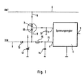
- FIG. 1 electrical system shown or the external wiring of a Voltage regulator 1 explained in more detail.
- the 1 shows a voltage regulator 1 with a power input 2, an output 3 and a signal input 4. Further inputs and outputs can be provided.
- the power input 2 is connected directly (or with the interposition of a fuse) to the positive pole of the vehicle electrical system via a line 5, which connects to the main line 6.
- the power input 2 of the voltage regulator 1 is also connected via a further line 8 to the secondary line 9 via an ignition switch (not shown) to the positive pole of the vehicle electrical system.
- Both the line 5, which leads to the main line 6, and the line 8, which leads to the secondary line 9, each have a diode 7, 10 connected to one another. This has the consequence that, depending on which line (main line 6 or secondary line 9), the higher voltage is present, this is forwarded to power input 2.
- the individual diodes 7, 10 can also be represented as small signal double diodes, since no capacitor charging currents have to flow through them.
- the secondary line 9 connects via a further line 11 the signal input 4 of the voltage regulator 1.
- Line 8 is via a buffer capacitor 12 with the negative pole of the vehicle electrical system connected, with a diode 13 in the secondary line 9 prevents the charged capacitor 12 from discharging can.
- the signal input 4 is through a resistor-capacitor combination 14.15 protected against voltage peaks.
- This protective device consists of a resistor 15 in line 11 and a capacitor 14, the signal input 4 connects to the negative pole of the vehicle electrical system.
- the Capacitance of the protective capacitor is much less than that of the buffer capacitor 12. Resistor 13 and capacitor 14 therefore form a common protective circuit, which is not refer to the actual idea of the invention.
- a small protective capacitor 16 (nF range) may be useful.
- the wiring of the voltage regulator works as follows.
- the voltage on the main line 6 is on via the diode 7 the power input 2 of the voltage regulator 1. If the Branch line 9 by operating the ignition switch with voltage is supplied, there is a voltage signal at signal input 4 as soon as the buffer capacitor 12 is charged. The loading time the buffer capacitor 12 is short because line 9 (IGN) has a low resistance is.
- the voltage regulator 1 As soon as a voltage signal is present at signal input 4, the voltage regulator 1 is activated so that at the output 3 a constant voltage is present, even if the Voltage on the main line 6 (BAT) changes because e.g. Further Consumers can be connected to the main line 6.
- BAT Voltage on the main line 6
- the buffer capacitor 12 ensures that for a relatively long period of signal input with sufficient Voltage is supplied so that the voltage regulator remains active.
- the long buffer time results from the Dimensioning (large capacity) of the buffer capacitor in With regard to the third case mentioned above and the high impedance of the signal input so that the voltage drop across the capacitor only takes place slowly via the high-impedance signal input.
- the buffer capacitor provides 12 that at least for a certain discharge time, one at the power input of voltage regulator 1 there is sufficient voltage.
- the Buffer capacitor on the secondary line 9 the task of the buffer capacitor, the immediately according to the prior art is connected to the power input 2.
- the buffer capacitor 12 thus both ensures that the main line is buffered as well as for buffering the secondary line.
- the capacity of the buffer capacitor 12 is on the necessary buffer time tuned for power input 2.
- this circuit can be used to practically the same buffering as in the prior art, while in the event of a voltage dip only on the secondary line the much longer discharge time of the buffer capacitor of the voltage regulator 1 remains active longer than with the solution in State of the art.
Landscapes
- Business, Economics & Management (AREA)
- Emergency Management (AREA)
- Engineering & Computer Science (AREA)
- Power Engineering (AREA)
- Direct Current Feeding And Distribution (AREA)
- Stand-By Power Supply Arrangements (AREA)
Description
Dies hat zur Folge, daß je nachdem, auf welcher Leitung (Hauptleitung 6 oder Nebenleitung 9), die höhere Spannung anliegt, diese zum Leistungseingang 2 weitergeleitet wird. Die einzelnen Dioden 7,10 können auch als kleine Signaldoppeldiode dargestellt werden, da durch sie keine Kondensator-Ladeströme fließen müssen.
Claims (4)
- Bordnetz eines Kraftfahrzeuges mit einer Hauptleitung (6), die unmittelbar oder über eine Schmelzsicherung mit der Fahrzeugbatterie verbunden ist, mit einer Nebenleitung (9), die über einen Zündschalter mit der Batterie verbunden ist, und mit einem Spannungsregler (1), der einen Leistungseingang (2), einen Signaleingang (4) sowie einen Ausgang (3) aufweist, wobei der Signaleingang (4) an die Nebenleitung (9)und der Leistungseingang über eine Diode (7) an die Hauptleitung (6) angeschlossen sind und wobei der Leistungseingang (2) über eine weitere Diode (10), die in Richtung zum Leistungseingang (2) durchlässig ist, mit der Nebenleitung verbunden ist, dadurch gekennzeichnet, daß ein Pufferkondensator (12) so an einen gemeinsamen Verbindungspunkt der Nebenleitung (9), der weiteren Diode (10) und des hochohmig ausgeführten Signaleingangs (4) angeschlossen ist, daß der Pufferkondensator (12) die Eingangsspannungen sowohl an dem Signaleingang (4) als auch an dem Leistungseingang (2) puffert, und daß die Kapazität des Pufferkondensators auf die notwendige Pufferzeit für den Leistungseingang (2) derart abgestimmt ist, daß bei Spannungszusammenbruch sowohl an der Hauptleitung (6) als auch an der Nebenleitung (9) am Leistungseingang (2) für eine gewisse Entladungszeit eine ausreichende Spannung geliefert wird.
- Bordnetz nach Anspruch 1, dadurch gekennzeichnet, daß die Verbindung des Leistungseingangs (2) mit der Hauptleitung (6) frei von einem Pufferkondensator ist.
- Bordnetz nach Anspruch 1 oder 2, dadurch gekennzeichnet, daß in der Nebenleitung (8) eine Diode (13) vorgesehen ist, über die der Pufferkondensator (12) geladen wird.
- Bordnetz nach einem der vorhergehenden Ansprüche, dadurch gekennzeichnet, daß der Signaleingang (4) mit einer Schutzbeschaltung (14, 15) versehen ist.
Applications Claiming Priority (3)
| Application Number | Priority Date | Filing Date | Title |
|---|---|---|---|
| DE19602171 | 1996-01-23 | ||
| DE1996102171 DE19602171A1 (de) | 1996-01-23 | 1996-01-23 | Beschaltung eines Spannungsreglers im Bordnetz eines Kfz's |
| PCT/EP1997/000242 WO1997027660A1 (de) | 1996-01-23 | 1997-01-20 | Beschaltung eines spannungsreglers im bordnetz eines kraftfahrzeuges |
Publications (2)
| Publication Number | Publication Date |
|---|---|
| EP0876701A1 EP0876701A1 (de) | 1998-11-11 |
| EP0876701B1 true EP0876701B1 (de) | 2002-11-13 |
Family
ID=7783364
Family Applications (1)
| Application Number | Title | Priority Date | Filing Date |
|---|---|---|---|
| EP97901557A Expired - Lifetime EP0876701B1 (de) | 1996-01-23 | 1997-01-20 | Bordnetz eines kraftfahrzeuges |
Country Status (5)
| Country | Link |
|---|---|
| US (1) | US6046512A (de) |
| EP (1) | EP0876701B1 (de) |
| JP (1) | JP2000504551A (de) |
| DE (2) | DE19602171A1 (de) |
| WO (1) | WO1997027660A1 (de) |
Families Citing this family (12)
| Publication number | Priority date | Publication date | Assignee | Title |
|---|---|---|---|---|
| JP3747618B2 (ja) * | 1998-03-17 | 2006-02-22 | 株式会社デンソー | 電源回路 |
| DE19913131B4 (de) | 1999-03-23 | 2004-07-22 | Siemens Ag | Stromversorgungssystem mit zwei Batterien unterschiedlicher Spannung |
| FR2795251B1 (fr) * | 1999-06-17 | 2001-09-07 | Magneti Marelli France | Dispositif d'alimentation de microprocesseur de vehicule automobile a resistance accrue aux chutes d'alimentation |
| DE10017590A1 (de) * | 2000-04-08 | 2001-10-11 | Mannesmann Vdo Ag | Stromversorgungseinrichtung |
| US6275017B1 (en) | 2000-05-25 | 2001-08-14 | Daimlerchrysler Corporation | Start-up circuit for voltage regulator with current foldback |
| US7191351B2 (en) * | 2001-09-12 | 2007-03-13 | Rockwell Automation Technologies, Inc. | Method and network for providing backup power to networked devices |
| US6924621B2 (en) | 2002-05-07 | 2005-08-02 | C.E. Niehoff & Co. | System and method for controlling electric load and battery charge in a vehicle |
| FR2874136B1 (fr) * | 2004-08-09 | 2009-11-20 | Valeo Securite Habitacle | Dispositif d'alimentation pour appareils electriques d'actionnement dans les vehicules automobiles |
| DE102006046032B3 (de) * | 2006-09-28 | 2007-10-31 | Siemens Ag | Steuervorrichtung mit Klemme 15-Halteschaltung |
| DE102008040547A1 (de) * | 2008-07-18 | 2010-01-21 | Robert Bosch Gmbh | Verfahren und Vorrichtung zur Betriebsspannungsversorgung für ein Steuergerät eines Kraftfahrzeuges |
| CN109643906B (zh) * | 2016-08-30 | 2023-07-04 | 三洋电机株式会社 | 管理装置和电源系统 |
| DE102017221621A1 (de) * | 2017-12-01 | 2019-06-06 | Bayerische Motoren Werke Aktiengesellschaft | Vorrichtung zur redundanten Energieversorgung zumindest eines Verbrauchers eines Kraftfahrzeugs aus einem Bordnetz, Bordnetz sowie Kraftfahrzeug |
Citations (1)
| Publication number | Priority date | Publication date | Assignee | Title |
|---|---|---|---|---|
| EP0646498A1 (de) * | 1993-10-04 | 1995-04-05 | Ford Motor Company Limited | Stromversorgung für elektrische Geräte in Fahrzeugen |
Family Cites Families (8)
| Publication number | Priority date | Publication date | Assignee | Title |
|---|---|---|---|---|
| JPS6087001U (ja) * | 1983-11-15 | 1985-06-15 | パイオニア株式会社 | 制御回路のバツクアツプ電源回路 |
| DE3435057C2 (de) * | 1984-09-25 | 1994-02-24 | Wabco Westinghouse Fahrzeug | Schutzschaltung gegen Unterspannungen im Bordnetz eines Kraftfahrzeuges |
| FR2605471B1 (fr) * | 1986-05-23 | 1991-05-17 | Ducellier & Cie | Perfectionnement a un dispositif d'alimentation electrique en regime temporaire des circuits auxiliaires d'un vehicule automobile |
| US5331211A (en) * | 1988-05-23 | 1994-07-19 | Nippondenso Co., Ltd. | Releasing circuit for actuating vehicular safety device |
| DE4109645A1 (de) * | 1991-03-23 | 1992-09-24 | Bosch Gmbh Robert | Einrichtung zur unterdrueckung von spannungseinbruechen |
| JPH0556577A (ja) * | 1991-08-27 | 1993-03-05 | Seikosha Co Ltd | 電源制御装置 |
| DE4219398A1 (de) * | 1992-06-13 | 1993-12-16 | Claas Ohg | Gepufferte Spannungsversorgung für Bordelektronik |
| DE4343011C2 (de) * | 1993-12-16 | 2002-08-29 | Bosch Gmbh Robert | Einrichtung zur Spannungsversorgung für eine Prozessoreinheit |
-
1996
- 1996-01-23 DE DE1996102171 patent/DE19602171A1/de not_active Withdrawn
-
1997
- 1997-01-20 DE DE59708715T patent/DE59708715D1/de not_active Expired - Lifetime
- 1997-01-20 EP EP97901557A patent/EP0876701B1/de not_active Expired - Lifetime
- 1997-01-20 US US09/117,125 patent/US6046512A/en not_active Expired - Lifetime
- 1997-01-20 WO PCT/EP1997/000242 patent/WO1997027660A1/de not_active Ceased
- 1997-01-20 JP JP52651297A patent/JP2000504551A/ja not_active Ceased
Patent Citations (1)
| Publication number | Priority date | Publication date | Assignee | Title |
|---|---|---|---|---|
| EP0646498A1 (de) * | 1993-10-04 | 1995-04-05 | Ford Motor Company Limited | Stromversorgung für elektrische Geräte in Fahrzeugen |
Also Published As
| Publication number | Publication date |
|---|---|
| DE59708715D1 (de) | 2002-12-19 |
| JP2000504551A (ja) | 2000-04-11 |
| EP0876701A1 (de) | 1998-11-11 |
| US6046512A (en) | 2000-04-04 |
| DE19602171A1 (de) | 1997-07-24 |
| WO1997027660A1 (de) | 1997-07-31 |
Similar Documents
| Publication | Publication Date | Title |
|---|---|---|
| EP1561269B1 (de) | Bordnetz zur versorgung mindestens eines verbrauchers mit erhöhten anforderungen an die verfügbarkeit des bordnetzes | |
| DE19854953C1 (de) | Batteriebordnetz mit Sicherheitsabschaltung | |
| DE19644858C2 (de) | Energiespeicherschutzvorrichtung für ein Fahrzeuginsassenschutzsystem | |
| EP0363356B1 (de) | Spannungsversorgung für elektronische geräte, insbesondere für sicherheitsrelevante geräte in kraftfahrzeugen | |
| DE102007017187B4 (de) | Bordnetz für ein Kraftfahrzeug und Verfahren zum Betreiben eines Bordnetzes eines Kraftfahrzeugs | |
| DE19542085B4 (de) | Sicherheitseinrichtung für Fahrzeuginsassen | |
| DE19913131A1 (de) | Stromversorgungssystem mit zwei Batterien unterschiedlicher Spannung | |
| DE3506487C2 (de) | Spannungsversorgungseinrichtung für eine Insassenschutzvorrichtung in einem Fahrzeug | |
| EP1241768A2 (de) | Anordnung und Verfahren zum Schutz eines Mehrspannungsbordnetzes gegen Spannungsüberschläge zwischen verschiedenen Spannungsebenen sowie gegen Verpolung von aussen | |
| DE10020141B4 (de) | Bordnetzsystem | |
| DE19651612A1 (de) | Elektronische Schaltung zur Spannungsversorgung | |
| WO1997027660A1 (de) | Beschaltung eines spannungsreglers im bordnetz eines kraftfahrzeuges | |
| EP3914482B1 (de) | Verfahren und vorrichtung zur regelung der elektrischen spannung für eine sicherheitsrelevante last | |
| EP1155919B1 (de) | Elektrisches Versorgungsnetz, insbesondere Bordnetz für ein Kraftfahrzeug, und Verfahren zur Detektion eines Kurzschlusses im Versorgungsnetz | |
| EP0732793B1 (de) | Schaltungsvorrichtung, insbesondere für sicherheitskritische Systeme in Fahrzeugen zur Personenbeförderung | |
| DE19813964A1 (de) | Bussystem mit einer Zentraleinheit eine Mehrzahl von Steuermodulen, insbesondere für Insassenschutzsysteme in Kraftfahrzeugen | |
| EP0539531B1 (de) | Einrichtung zur unterdrückung von spannungseinbrüchen | |
| WO2004017481A1 (de) | Sensor-schutzschaltung | |
| WO2000042688A1 (de) | Schaltungsanordnung zum schutz gegen spannungsverpolung | |
| DE68917076T2 (de) | Für ein Kraftfahrzeug anwendbares Vielfachpfadübertragungssystem. | |
| EP0872940A2 (de) | Verfahren zum Betreiben eines Energieversorgungsgeräts und Energieversorungsgerät | |
| EP0965501A2 (de) | Vorrichtung zum Zünden eines Zündelements eines Kraftfahrzeug-Insassenschutzmittels | |
| WO2004051823A1 (de) | Mobile stromversorgungseinheit mit einem autarkiekondensator | |
| EP0731003A1 (de) | Schaltung zur Steuerung und Zündung von Insassen-Schutzvorrichtungen | |
| EP1220768B1 (de) | Zündeinrichtung für eine pyrotechnische insassenschutzeinrichtung |
Legal Events
| Date | Code | Title | Description |
|---|---|---|---|
| PUAI | Public reference made under article 153(3) epc to a published international application that has entered the european phase |
Free format text: ORIGINAL CODE: 0009012 |
|
| 17P | Request for examination filed |
Effective date: 19980824 |
|
| AK | Designated contracting states |
Kind code of ref document: A1 Designated state(s): DE FR GB |
|
| RAP1 | Party data changed (applicant data changed or rights of an application transferred) |
Owner name: CONTINENTAL TEVES AG & CO. OHG |
|
| GRAG | Despatch of communication of intention to grant |
Free format text: ORIGINAL CODE: EPIDOS AGRA |
|
| RTI1 | Title (correction) |
Free format text: MOTOR VEHICLE POWER SUPPLY NETWORK |
|
| 17Q | First examination report despatched |
Effective date: 20020125 |
|
| GRAG | Despatch of communication of intention to grant |
Free format text: ORIGINAL CODE: EPIDOS AGRA |
|
| GRAH | Despatch of communication of intention to grant a patent |
Free format text: ORIGINAL CODE: EPIDOS IGRA |
|
| GRAH | Despatch of communication of intention to grant a patent |
Free format text: ORIGINAL CODE: EPIDOS IGRA |
|
| GRAA | (expected) grant |
Free format text: ORIGINAL CODE: 0009210 |
|
| AK | Designated contracting states |
Kind code of ref document: B1 Designated state(s): DE FR GB |
|
| PG25 | Lapsed in a contracting state [announced via postgrant information from national office to epo] |
Ref country code: GB Free format text: LAPSE BECAUSE OF FAILURE TO SUBMIT A TRANSLATION OF THE DESCRIPTION OR TO PAY THE FEE WITHIN THE PRESCRIBED TIME-LIMIT Effective date: 20021113 |
|
| REG | Reference to a national code |
Ref country code: GB Ref legal event code: FG4D Free format text: NOT ENGLISH |
|
| REF | Corresponds to: |
Ref document number: 59708715 Country of ref document: DE Date of ref document: 20021219 |
|
| GBV | Gb: ep patent (uk) treated as always having been void in accordance with gb section 77(7)/1977 [no translation filed] |
Effective date: 20021113 |
|
| ET | Fr: translation filed | ||
| PLBE | No opposition filed within time limit |
Free format text: ORIGINAL CODE: 0009261 |
|
| STAA | Information on the status of an ep patent application or granted ep patent |
Free format text: STATUS: NO OPPOSITION FILED WITHIN TIME LIMIT |
|
| 26N | No opposition filed |
Effective date: 20030814 |
|
| PGFP | Annual fee paid to national office [announced via postgrant information from national office to epo] |
Ref country code: FR Payment date: 20120202 Year of fee payment: 16 |
|
| PGFP | Annual fee paid to national office [announced via postgrant information from national office to epo] |
Ref country code: DE Payment date: 20120131 Year of fee payment: 16 |
|
| REG | Reference to a national code |
Ref country code: DE Ref legal event code: R231 Ref document number: 59708715 Country of ref document: DE |
|
| PG25 | Lapsed in a contracting state [announced via postgrant information from national office to epo] |
Ref country code: DE Free format text: LAPSE BECAUSE OF THE APPLICANT RENOUNCES Effective date: 20120811 |
|
| REG | Reference to a national code |
Ref country code: FR Ref legal event code: ST Effective date: 20130930 |
|
| PG25 | Lapsed in a contracting state [announced via postgrant information from national office to epo] |
Ref country code: FR Free format text: LAPSE BECAUSE OF NON-PAYMENT OF DUE FEES Effective date: 20130131 |