EP0876990A2 - Notaus-Stoppbremse für Kräne - Google Patents
Notaus-Stoppbremse für Kräne Download PDFInfo
- Publication number
- EP0876990A2 EP0876990A2 EP98250119A EP98250119A EP0876990A2 EP 0876990 A2 EP0876990 A2 EP 0876990A2 EP 98250119 A EP98250119 A EP 98250119A EP 98250119 A EP98250119 A EP 98250119A EP 0876990 A2 EP0876990 A2 EP 0876990A2
- Authority
- EP
- European Patent Office
- Prior art keywords
- brake
- emergency stop
- levers
- lever
- bearings
- Prior art date
- Legal status (The legal status is an assumption and is not a legal conclusion. Google has not performed a legal analysis and makes no representation as to the accuracy of the status listed.)
- Withdrawn
Links
- 238000009423 ventilation Methods 0.000 claims description 7
- 239000007788 liquid Substances 0.000 claims description 4
- 239000000446 fuel Substances 0.000 claims description 3
- 238000013461 design Methods 0.000 description 4
- 230000007246 mechanism Effects 0.000 description 4
- 238000009434 installation Methods 0.000 description 3
- 229910000831 Steel Inorganic materials 0.000 description 2
- 238000010276 construction Methods 0.000 description 2
- 239000010959 steel Substances 0.000 description 2
- 238000010521 absorption reaction Methods 0.000 description 1
- 230000006978 adaptation Effects 0.000 description 1
- 230000005540 biological transmission Effects 0.000 description 1
- 238000005266 casting Methods 0.000 description 1
- 230000005489 elastic deformation Effects 0.000 description 1
- 229910052500 inorganic mineral Inorganic materials 0.000 description 1
- 238000011835 investigation Methods 0.000 description 1
- 238000004519 manufacturing process Methods 0.000 description 1
- 239000002184 metal Substances 0.000 description 1
- 229910052751 metal Inorganic materials 0.000 description 1
- 150000002739 metals Chemical class 0.000 description 1
- 239000011707 mineral Substances 0.000 description 1
- 239000000565 sealant Substances 0.000 description 1
- 230000035939 shock Effects 0.000 description 1
- 238000012549 training Methods 0.000 description 1
- 238000012546 transfer Methods 0.000 description 1
- 238000013022 venting Methods 0.000 description 1
Images


Classifications
-
- F—MECHANICAL ENGINEERING; LIGHTING; HEATING; WEAPONS; BLASTING
- F16—ENGINEERING ELEMENTS AND UNITS; GENERAL MEASURES FOR PRODUCING AND MAINTAINING EFFECTIVE FUNCTIONING OF MACHINES OR INSTALLATIONS; THERMAL INSULATION IN GENERAL
- F16D—COUPLINGS FOR TRANSMITTING ROTATION; CLUTCHES; BRAKES
- F16D55/00—Brakes with substantially-radial braking surfaces pressed together in axial direction, e.g. disc brakes
- F16D55/02—Brakes with substantially-radial braking surfaces pressed together in axial direction, e.g. disc brakes with axially-movable discs or pads pressed against axially-located rotating members
- F16D55/22—Brakes with substantially-radial braking surfaces pressed together in axial direction, e.g. disc brakes with axially-movable discs or pads pressed against axially-located rotating members by clamping an axially-located rotating disc between movable braking members, e.g. movable brake discs or brake pads
- F16D55/224—Brakes with substantially-radial braking surfaces pressed together in axial direction, e.g. disc brakes with axially-movable discs or pads pressed against axially-located rotating members by clamping an axially-located rotating disc between movable braking members, e.g. movable brake discs or brake pads with a common actuating member for the braking members
- F16D55/2245—Brakes with substantially-radial braking surfaces pressed together in axial direction, e.g. disc brakes with axially-movable discs or pads pressed against axially-located rotating members by clamping an axially-located rotating disc between movable braking members, e.g. movable brake discs or brake pads with a common actuating member for the braking members in which the common actuating member acts on two levers carrying the braking members, e.g. tong-type brakes
-
- B—PERFORMING OPERATIONS; TRANSPORTING
- B66—HOISTING; LIFTING; HAULING
- B66D—CAPSTANS; WINCHES; TACKLES, e.g. PULLEY BLOCKS; HOISTS
- B66D5/00—Braking or detent devices characterised by application to lifting or hoisting gear, e.g. for controlling the lowering of loads
- B66D5/02—Crane, lift hoist, or winch brakes operating on drums, barrels, or ropes
- B66D5/12—Crane, lift hoist, or winch brakes operating on drums, barrels, or ropes with axial effect
- B66D5/14—Crane, lift hoist, or winch brakes operating on drums, barrels, or ropes with axial effect embodying discs
-
- F—MECHANICAL ENGINEERING; LIGHTING; HEATING; WEAPONS; BLASTING
- F16—ENGINEERING ELEMENTS AND UNITS; GENERAL MEASURES FOR PRODUCING AND MAINTAINING EFFECTIVE FUNCTIONING OF MACHINES OR INSTALLATIONS; THERMAL INSULATION IN GENERAL
- F16D—COUPLINGS FOR TRANSMITTING ROTATION; CLUTCHES; BRAKES
- F16D2121/00—Type of actuator operation force
- F16D2121/02—Fluid pressure
- F16D2121/12—Fluid pressure for releasing a normally applied brake, the type of actuator being irrelevant or not provided for in groups F16D2121/04 - F16D2121/10
Definitions
- the invention relates to an emergency stop brake for cranes, in particular for Transport of liquid fuels, according to the preamble of claim 1.
- a disc brake for industrial systems is disclosed in DE-OS 2817695.
- This has four brake levers, with four brake shoes provided on the brake levers, with one provided between the brake levers or the brake shoes Brake disc, with at least one brake spring generating the braking force and with a brake release device acting on the brake levers.
- the brake release device has only one ventilation unit, but two ventilation mechanisms, the two Release mechanisms are connected to each other via a joint parallelogram and a release mechanism between two brake levers is effective. From Kinematic sequence ago the known arrangement is structurally complex and for the special requirements placed on an emergency stop brake not suitable. In addition, the transferable forces are limited.
- an emergency stop brake designed in a compact design with short, rigid levers, strong coil spring and large bearings and a piston-cylinder unit as Ventilation device. This is in the middle of the lever, articulated on both levers, arranged between the brake spring and the bearing.
- the one designed according to the invention Emergency stop brake does not have a fixed caliper, so that due to the mobility of the Both levers always apply the same forces to the brake shoes. It will be a Forces parallelogram formed, which is also a misalignment of the brake in the Swivel plane allowed.
- a specified jaw ventilation path of more than The axial play of the large rope drums can be compensated for by 1 mm, as well the blow due to bearing play and elastic compliance of the Substructure.
- An inclination of the brake disc in the perpendicular to The level lying on the swivel plane can be taken into account when installing the brake will. Alternatively, this can also be done by calotte mounting of the brake shoes be balanced.
- the piston-cylinder unit arranged between the brake spring and the bearing takes on the one hand the function of the venting device and on the other hand a holding function for the emergency stop brake
- the piston-cylinder unit acts as an attenuator to prevent the so-called bounce. This means a brief re-opening of the brake when actuated. This bounce is particularly to be expected if the construction of the brake is very stiff , the mass is large and the system is weakly damped.
- the second embodiment is a standing version with a torque transfer of the stored spring energy to the brake shoes.
- Lever and brake shoes are connected to each other via a continuous shaft.
- the spring is not supported between both levers, but via a pull rod on the outside of a lever.
- the connection to the other lever is made via the pull rod, which is connected to the open one Reaches through the holes of the two levers.
- torsion of the shaft prevents the impact shock like a torsion bar spring.
- Both versions are characterized by slightly moved masses negligible friction shunts. In combination with the strong brake spring engagement times of less than 200 m sec. Also the rare case a break in the shaft of the cable drum can be safely intercepted. The Arrangement of a corresponding sensor system is assumed.
- the unfavorable boundary conditions especially in a steel mill, such as high ones Ambient temperatures (up to the blow), large fluctuation range of the Ambient temperatures, vibrations, elastic deformations of the Substructure, production-related emissions of metals and minerals Dusts must be taken into account by designing the sealant and the bearings will.
- FIG. 1 and 2 is a first in a plan view and in a side view Embodiment of an emergency stop brake designed according to the invention shown.
- the main components are the spring accumulator in the form of a Coil spring 1, which is clamped between two pivotally mounted lifts 2,3 is.
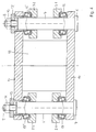
- From the side view (Fig.2) or section (Fig. 4) shows that each lever 2, 3 from two parallel spaced tabs 2.1; 2.2 or 3.1; 3.2 exists.
- the two tabs 2.1; 2.2 or 3.1; 3.2 are each over a Bolzano 4,5 connected to each other.
- the bolt 4.5 has a head 6.7 and on End of a threaded section 8.9. It is attached using a nut 10, 11, which comes to rest on a socket 12, 13 (FIG. 4).
- a piston-cylinder unit arranged on both levers 2, 3.
- This consists of one Cylinder 27 and a double-acting one not shown here Piston.
- the piston rod 28 guided outwards is at the end with an eye 29 provided for linkage to lever 2.
- the free end of the cylinder 27 has also an eye 30 through which a bolt 31 extends.
- the levers are 2,3 appropriately trained in terms of great rigidity. This applies in particular to the cross-sectional widening in the area of the bearings 16, 17.
- the link bearing for the piston-cylinder unit between the plates 2.1, 2.2 or 3.1, 3.2 a web plate 36, 36 'arranged upright.
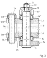
- FIG. 3 shows the section in the direction A-A in FIG. 1 on an enlarged scale shown.
- the respective brake shoes 19, 20 FIG. 1
- two tabs 32.1, 32.2 or spaced apart from one another 33.1, 33.2 the parts marked 33.n and 38.n are shown in the Figures not shown. These parts correspond to the parts with 32.n and 37.n. are designated for the bolt 21 and belong to the bolt 22, the head of which is shown in FIG. 1 is indicated by 35.
- the respective tab 32.1, 32.2 or 33.1, 33.2 has one Bore through which the corresponding bolt 21, 22 engages.
- the bolt 21, 22 is provided with a head 34, 35, which on the upper tab 32.2 or 33.2 comes to the plant.
- the bolt 20, 21 in Contact area of a guide bush 37.1, 37.2, 38.1, 38.2 comprises the also serves as a warehouse.
- the lever arm between the bearings 16, 16 ' and the bolt 21, 22 is short, is for stiffening between the tabs 2.1, 2.2 or 3.1, 3.2 a web plate 23, 23 'arranged upright.
- FIG. 4 shows, on an enlarged scale, a section in the direction D-D in FIG. 1.
- This illustration shows in particular the design of the bearings 16, 16 ', 17, 17' are designed as tapered roller bearings in this embodiment. But it could can also be a plain bearing.
- the two bearings 16, 16 'and 17, 17' can be braced against each other.
- an angle plate 18 is arranged between the base plate and the cover plate 15, an angle plate 18 is arranged. This is intended in particular to Deflection of the cover plate 15 can be prevented, only as an angled Tab is designed to, as can be seen in Figure 1, free accessibility of to enable the piston-cylinder unit and the brake spring 1 above.
- FIGS 5 and 6 show a second embodiment of an inventive trained emergency stop brake, the same reference numerals for the same parts have been used.
- this standing embodiment are on a level Carrier plate 40 two support brackets 41, 41 'and 42, 42' spaced from one another arranged. One extends through the respective pair of support stands 41, 41 'and 42, 42' Shaft 43, 44, which is fixedly connected to a short brake lever 45, 46.
- a brake lever 45,46 is articulated to a brake shoe 47,48.
- the arrangement of the usual brake pad on the end face of the respective brake shoe 47.48 omitted here. Between the two brake shoes 47, 48 is in an emergency Brake disc 26 to be braked.
- the linkage of the brake shoe 47.48 on the respective brake lever 45, 46 takes place via a through the brake lever 45, 46 extending bolt 49.50.
- the shaft bearing 43.54 'forming the jaw bearing 51.51' or 52.52 'through the support bracket pairs 41.41 'and 42.42' and is firmly connected to the levers 53.1, 53.2, 54.1, 54.2. in the The levers are different from the first embodiment according to FIGS. 1 to 4 53.54 trained differently here.
- Each lever 53, 54 consists of a pair parallel tabs 53.1, 53.2 or 54.1, 54.2, which via a sleeve 72, 73 are interconnected.
- lever 53 on the right is angled at right angles.
- levers 53, 54 with one each Plate 55.56 provided.
- Extends through holes 57.58 in the plates 55.56 a rod 59, which is provided at both ends with a threaded section 60, 61 is.
- Stop pieces 62,63 arranged, between which the brake spring 1 can be tensioned.
- the position at the right end shown with dashed lines shows the Installation position before tensioning the brake spring 1. The tensioning is done by means of a nut 64 which comes to rest on a washer 65.
- the rod 59 has two spherical caps 66, 67 arranged on the plates Support 55.56 inserts 68.69.
- the rod 59 is also a nut 70 for adjusting the counter-holding force arranged, which comes to rest on a washer 71.
- the brake spring 1 presses the piston rod 28 and thus the piston into the cylinder 27 and the two pivoting levers 53, 54 pivot the two short brake levers via the shaft 43, 44 45.46 and press the brake shoes 47.48 against the brake disc 26.
Landscapes
- Engineering & Computer Science (AREA)
- Mechanical Engineering (AREA)
- General Engineering & Computer Science (AREA)
- Braking Arrangements (AREA)
Abstract
Description

- große Backenlüftung von mehr als 1 mm (Ausgleich des Lagerspieles der Seiltrommel)
- Anpassung an die mögliche Schiefstellung der Bremsscheibe
- Aufnahme großer Bremsmomente
- kurze Einfallzeit von < 200 m sec.
- Vermeidung von Prellschlag
- Zuverlässigkeit des Systems in Erfüllung der Bereitschaftssituation
- Berücksichtigung der Einsatzbedingungen beim Transport feuerflüssiger Massen
- Reduzierung der Kraftnebenschlüsse
- prellschlagarme Bremse
- fehlertolerantes Bremssystem
- gedämpfter Kraftaufbau
- schleiffreier Betrieb
- massereduziertes Betätigungssystem
- anschlußreduziertes Betätigungssystem
- rückwirkungsfreie Einhaltung der Bremsebene
- Figur 1
- eine Draufsicht einer ersten Ausführungsform einer erfindungsgemäß ausgebildeten Notaus-Stoppbremse
- Figur 2
- eine Seitenansicht
- Figur 3
- im vergrößerten Maßstab einen Schnitt in Richtung A-A in Fig. 1
- Figur 4
- im vergrößerten Maßstab einen Schnitt in Richtung D-D in Fig. 1
- Figur 5
- eine Vorderansicht mit teilweise Aufbruch einer zweiten Ausführungsform einer erfindungsgemäß ausgebildeten Notaus-Stoppbremse
- Figur 6
- eine Seitenansicht
Claims (13)
- Notaus-Stoppbremse für Krane, insbesondere zum Transport feuerflüssiger Massen, mit zwei einander gegenüberliegenden in Schwenklagern gelagerte Heben, mit einer zwischen in Backenlager gelagerten Bremsbacken vorgesehenen Bremsscheibe, mit einer am offenen Ende der Hebel angeordnete, die Bremskraft erzeugende Bremsfeder und mit einer an die Hebel angreifenden Bremslüfteinrichtung, wobei an der Bremsscheibe mindestens zwei symmetrisch über den Umfang verteilt angeordnete Notaus-Stoppbremsen vorgesehen sind,
dadurch gekennzeichnet,
daß im mittleren Bereich der kurzen, steifen Hebel (2, 3) zwischen der als funktionsgerecht bemessenen Spiralfeder ausgebildeten Bremsfeder (1) und den groß bemessenen Lagern (16, 17) eine an beiden Hebeln (2, 3) angelenkte Kolben-Zylindereinheit als Lüfteinrichtung angeordnet ist. - Notaus-Stoppbremse nach Anspruch 1
dadurch gekennzeichnet,
daß die Bremseinrichtung liegend angeordnet ist und die Bremsbacken (19, 20) an im Bremsscheibenbereich liegenden Ende der als Bremshebel ausgebildeten Hebel (2, 3) angeordnet sind und die Lager (16, 17) zwischen den Backenlagern (34, 35) und den Anlenklagern für die Kolben-Zylindereinheit sich befinden, wobei der Abstand zwischen Backenlager (34, 35) und den Lagern (16, 17) signifikant geringer ist als der zwischen den Lagern (16, 17) und Mittelachse Bremsfeder (1). - Notaus-Stoppbremse nach Anspruch 2,
dadurch gekennzeichnet,
daß das Verhältnis der Abstände mindestens 1:3 beträgt. - Notaus-Stoppbremse nach Anspruch 2 oder 3,
dadurch gekennzeichnet,
daß die Hebel (2, 3) im Bereich der Lager (16, 17) eine in der Längsebene liegende größere Erstreckung aufweisen als die daran anschließenden Bereiche. - Notaus-Stoppbremse nach einem der Ansprüche 2 bis 4,
dadurch gekennzeichnet,
daß zur Versteifung der Bremseinrichtung zwischen einander gegenüberliegenden Laschen (2.1, 2.2 bzw. 3.1, 3.2) der Hebel (2, 3) einerseits und zwischen einem Bodenblech (14) und einem Deckblech (15) andererseits Stegbleche (23, 23', 36, 36') bzw. ein Winkelblech (18) hochkantstehend angeordnet sind. - Notaus-Stoppbremse nach einem der Ansprüche 2 bis 5,
dadurch gekennzeichnet,
daß in der Längsebene der jeweilige Hebel (2, 3) zwischen Lager (16, 17) und Anlenklager eine in Richtung der Bremsscheibe (26) liegende Abwinkelung aufweist. - Notaus-Stoppbremse nach Anspruch 6,
dadurch gekennzeichnet,
daß die Abwinkelung mehr als 30° beträgt. - Notaus-Stoppbremse nach Anspruch 1,
dadurch gekennzeichnet,
daß die Bremseinrichtung stehend angeordnet ist und Bremsbacken (47, 48) einschließlich Backenlager (51, 51', 52, 52') einerseits und Hebel (53, 54) einschließlich Bremsfeder (1) und Kolben-Zylindereinheit andererseits parallel nebeneinander auf einer ebenen Trägerplatte (40) angeordnet sind und durch eine durch das jeweilige Backenlager (51, 52) und Lager sich erstreckende schwenkbare Welle (43, 44) in Wirkverbindung miteinander stehen. - Notaus-Stoppbremse nach Anspruch 8,
dadurch gekennzeichnet,
daß auf der ebenen Trägerplatte (40) je Backenlager (51, 52) zwei parallel im Abstand von einander liegende Stützböcke (41, 41', 42, 42') befestigt sind, zwischen denen ein kurzer Bremshebel (45, 46) angeordnet ist, an dessen einem Ende angelenkt die Bremsbacke (47, 48) befestigt ist und dessen anderes Ende mit der durch ihn sich erstreckenden Welle (43, 44) fest verbunden ist und die über die Stützböcke (41, 42) hinaus sich erstreckende Welle (43, 44) mit dem offenen Ende der Hebel (53, 54) fest verbunden ist. - Notaus-Stoppbremse nach Anspruch 8 oder 9,
dadurch gekennzeichnet,
daß ein Hebel (54) vom Lager aus nahezu gradlinig nach oben sich erstreckt und der andere Hebel (53) eine rechtwinklig auf den anderen Hebel (54) zugehende Abwinkelung aufweist und die Bremsfeder (1) am abgewinkelten Hebel (53) angeordnet ist. - Notaus-Stoppbremse nach Anspruch 10,
dadurch gekennzeichnet,
daß beide Hebel (53, 54) am offenen Ende plattenartig (55, 56) ausgebildet sind und durch eine in beiden Platten (55, 56) angeordnete Bohrung (57, 58) eine Stange (59) sich erstreckt, auf der Anschlagstücke (62, 63) zur Aufnahme der Bremsfeder (1) angeordnet sind. - Notaus-Stoppbremse nach Anspruch 11,
dadurch gekennzeichnet,
daß beide Enden der Stange (59) mit je einem Gewindeabschnitt (60, 61) zur Aufnahme einer Mutter (64, 70) versehen sind. - Notaus-Stoppbremse nach Anspruch 10 oder 11,
dadurch gekennzeichnet,
daß die Abstützung der Stange (59) im plattenartigen Endbereich der Hebel (53, 54) durch je einen Kalottenkörper (66, 67) erfolgt.
Applications Claiming Priority (2)
| Application Number | Priority Date | Filing Date | Title |
|---|---|---|---|
| DE1997119079 DE19719079C1 (de) | 1997-04-30 | 1997-04-30 | Notaus-Stoppbremse für Krane |
| DE19719079 | 1997-04-30 |
Publications (2)
| Publication Number | Publication Date |
|---|---|
| EP0876990A2 true EP0876990A2 (de) | 1998-11-11 |
| EP0876990A3 EP0876990A3 (de) | 1999-10-13 |
Family
ID=7828760
Family Applications (1)
| Application Number | Title | Priority Date | Filing Date |
|---|---|---|---|
| EP98250119A Withdrawn EP0876990A3 (de) | 1997-04-30 | 1998-04-03 | Notaus-Stoppbremse für Kräne |
Country Status (2)
| Country | Link |
|---|---|
| EP (1) | EP0876990A3 (de) |
| DE (1) | DE19719079C1 (de) |
Cited By (1)
| Publication number | Priority date | Publication date | Assignee | Title |
|---|---|---|---|---|
| CN105584950A (zh) * | 2016-03-16 | 2016-05-18 | 北京普世科石油机械新技术有限公司 | 一种自动保持恒间隙工作安全一体化制动油缸 |
Families Citing this family (2)
| Publication number | Priority date | Publication date | Assignee | Title |
|---|---|---|---|---|
| DE502007007014D1 (de) | 2007-11-12 | 2011-06-01 | Thyssenkrupp Elevator Ag | Bremsvorrichtung zum Bremsen eines Fahrkorbs |
| DE102010023700B4 (de) * | 2010-06-14 | 2012-01-26 | Pintsch Bubenzer Gmbh | Stellvorrichtung für eine selbstverstärkende Bremseinrichtung und selbstverstärkende Bremseinrichtung |
Family Cites Families (3)
| Publication number | Priority date | Publication date | Assignee | Title |
|---|---|---|---|---|
| DE2817695C2 (de) * | 1978-04-22 | 1984-07-05 | Norbert Dipl.-Ing. 4130 Moers Asmus | Teilbelagscheibenbremse |
| US4696377A (en) * | 1985-09-27 | 1987-09-29 | Ltv Energy Products Company | Brake system for drawworks |
| CA2036363C (en) * | 1990-04-13 | 1999-08-24 | William Sheridan | Disk brake for elevator |
-
1997
- 1997-04-30 DE DE1997119079 patent/DE19719079C1/de not_active Expired - Lifetime
-
1998
- 1998-04-03 EP EP98250119A patent/EP0876990A3/de not_active Withdrawn
Cited By (2)
| Publication number | Priority date | Publication date | Assignee | Title |
|---|---|---|---|---|
| CN105584950A (zh) * | 2016-03-16 | 2016-05-18 | 北京普世科石油机械新技术有限公司 | 一种自动保持恒间隙工作安全一体化制动油缸 |
| CN105584950B (zh) * | 2016-03-16 | 2018-02-02 | 北京普世科石油机械新技术有限公司 | 一种自动保持恒间隙工作安全一体化制动油缸 |
Also Published As
| Publication number | Publication date |
|---|---|
| DE19719079C1 (de) | 1998-09-24 |
| EP0876990A3 (de) | 1999-10-13 |
Similar Documents
| Publication | Publication Date | Title |
|---|---|---|
| EP1067084B1 (de) | Vorrichtung und Verfahren zur Verhinderung von Vertikalverschiebungen und Vertikalschwingungen an Lastaufnahmemitteln von Vertikalförderanlagen | |
| DE102011053178B3 (de) | Reibungsbremse mit einer senkrecht zur Zuspannrichtung wirkenden Aktoreinheit | |
| DE2837547C2 (de) | Zugkräfte zwischen zwei Bauteilen aufnehmendes, höhenverstellbares und Kippbewegungen zulassendes Lager | |
| EP0065176A2 (de) | Einrichtung zum Aufbringen der Last auf balkenförmige Aufnehmer | |
| EP0396870B1 (de) | Waage mit Ueberlastschutz | |
| DE3019468A1 (de) | Fahrwerk fuer eisenbahnfahrzeuge | |
| EP1770047A1 (de) | Vorrichtung zum Aufhängen einer Schiene, insbesondere eine Fahrschiene eines Hängeförderers oder eines Hebezeuges | |
| DE102017101028A1 (de) | Bremszangeneinheit | |
| DE19719079C1 (de) | Notaus-Stoppbremse für Krane | |
| DE2421874C3 (de) | Laufstabilisator für ein Hochgeschwindigkeits-Schienenfahrzeug | |
| DE2400198A1 (de) | Sicherheitsbremse | |
| DE60123490T2 (de) | Vorrichtung für eine verriegelungseinheit eines behälter-ladegeschirrs | |
| DE102007052280B4 (de) | Richtungsunabhängig ansprechender Geschwindigkeitsbegrenzer | |
| EP0438660B1 (de) | Kraftmesseinrichtung für auskragende Lasten | |
| DE102021120048B4 (de) | Scheibenbremse für ein Nutzfahrzeug | |
| DE29708129U1 (de) | Notaus-Stoppbremse für Krane | |
| DE3103538C2 (de) | Schienenfahrzeug für schwere Lasten, insbesondere für metallurgische Gefäße | |
| DE3617026C2 (de) | ||
| DE3409158A1 (de) | Halterungsanordnung von bremsklotzeinheiten an schienenfahrzeugen | |
| EP1605174A2 (de) | Elastische Lagerung einer Brems- und Klammeinrichtung | |
| DE60220589T2 (de) | Scheibenbremse, insbesondere für Industriegebrauch | |
| DE19846671A1 (de) | Treibscheibenbremse mit erhöhter Redundanz | |
| DE4206342C2 (de) | Scheibenbremsgestänge für Schienenfahrzeuge mit querverschieblichem Radsatz | |
| EP1825164B1 (de) | Scheibenbremse für ein fahrzeug | |
| DE19635245C2 (de) | Sicherheits-Bremsvorrichtung für Seilförderanlagen |
Legal Events
| Date | Code | Title | Description |
|---|---|---|---|
| PUAI | Public reference made under article 153(3) epc to a published international application that has entered the european phase |
Free format text: ORIGINAL CODE: 0009012 |
|
| AK | Designated contracting states |
Kind code of ref document: A2 Designated state(s): BE DE FR GB NL |
|
| AX | Request for extension of the european patent |
Free format text: AL;LT;LV;MK;RO;SI |
|
| PUAL | Search report despatched |
Free format text: ORIGINAL CODE: 0009013 |
|
| AK | Designated contracting states |
Kind code of ref document: A3 Designated state(s): AT BE CH CY DE DK ES FI FR GB GR IE IT LI LU MC NL PT SE |
|
| AX | Request for extension of the european patent |
Free format text: AL;LT;LV;MK;RO;SI |
|
| 17P | Request for examination filed |
Effective date: 19990928 |
|
| AKX | Designation fees paid | ||
| RBV | Designated contracting states (corrected) |
Designated state(s): BE DE FR GB NL |
|
| REG | Reference to a national code |
Ref country code: DE Ref legal event code: 8566 |
|
| GRAH | Despatch of communication of intention to grant a patent |
Free format text: ORIGINAL CODE: EPIDOS IGRA |
|
| STAA | Information on the status of an ep patent application or granted ep patent |
Free format text: STATUS: THE APPLICATION HAS BEEN WITHDRAWN |
|
| 18W | Application withdrawn |
Effective date: 20030429 |