EP0877107A2 - Procédé et appareil pour le transport d'un groupe de pots - Google Patents
Procédé et appareil pour le transport d'un groupe de pots Download PDFInfo
- Publication number
- EP0877107A2 EP0877107A2 EP98105377A EP98105377A EP0877107A2 EP 0877107 A2 EP0877107 A2 EP 0877107A2 EP 98105377 A EP98105377 A EP 98105377A EP 98105377 A EP98105377 A EP 98105377A EP 0877107 A2 EP0877107 A2 EP 0877107A2
- Authority
- EP
- European Patent Office
- Prior art keywords
- carrier
- cans
- group
- textile machine
- magazine
- Prior art date
- Legal status (The legal status is an assumption and is not a legal conclusion. Google has not performed a legal analysis and makes no representation as to the accuracy of the status listed.)
- Granted
Links
Images


Classifications
-
- D—TEXTILES; PAPER
- D01—NATURAL OR MAN-MADE THREADS OR FIBRES; SPINNING
- D01H—SPINNING OR TWISTING
- D01H9/00—Arrangements for replacing or removing bobbins, cores, receptacles, or completed packages at paying-out or take-up stations ; Combination of spinning-winding machine
Definitions
- the present invention relates to a method according to the preamble of the claim 1 and an apparatus for performing this method.
- the object of the present invention is therefore a method and a corresponding one To create device that can transport into the workplace of the Route as well as simplified from this.
- the method according to the invention can be conveniently according to Claim 2 be trained. In this way the provision and collection take place of a can carrier regardless of the filling of the cans.
- the sliver processing textile machines e.g. B. flyers or open-end spinning machines
- the can carrier and also the working position of the textile machine and / or the storage position of the can magazine with regard to its dimensions are coordinated with one another according to claim 5.
- monitoring can shorten the waiting time on the route the filling work can be achieved.
- monitoring can shorten the waiting time on the route the filling work can be achieved.
- B. triggering an acoustic or optical signal or an exchange a can carrier according to claim 9 is provided.
- a device according to FIGS Features provided according to claim 10. Because the can carrier brought into the route also during the filling of the cans arranged on the can carrier Jug group remains on the line and only after the cans have been filled Leaving the route together with this group of pitchers will be used for the exchange these cans between the transport vehicle (can car) and the route only simple movement and control processes are required, which means construction costs, the manufacture and the material for the elements required for this as well as saving time during work.
- jug magazine and / or textile machine on the one hand are preferably jug magazine and / or textile machine on the one hand and can carrier on the other hand dimensionally according to claim 13 Voted.
- the displacement device of the route can be exchanged, even if still not all cans of a group of cans on a can carrier is filled with sliver again. While one pitcher group is filled another can carrier with filled cans can be picked up and another Can carriers with empty cans are provided.
- the can carrier can be designed in different ways; a special one simpler and therefore more cost-effective can carrier results in training accordingly Claim 15 and possibly 16. Further appropriate training of the can carrier result from the claims up to 17 to 23.
- the can carrier can be transported manually or automatically.
- the can carrier is expediently carried by one according to claims 24 and possibly 25 trained can wagons.
- a can carrier holder is preferably provided on the individual components of the system, wherein as Component "a stretch as a sliver-supplying textile machine, a sliver-consuming textile machine and a jug magazine, always in the number or in the majority.
- monitoring and control can be carried out according to a or more of claims 35 to 37 may be provided.
- both the method according to the invention and the device according to the invention are simple and also allow subsequent implementation on existing ones Machines or systems. Because the cans of a group of cans not only during transport, but also for filling up as a can group submitted together to the route and after filling from here again can be picked up as a complete can group, the taxable as well the time required for a can change, which in the sense of the present Invention is seen as part of the can transport, reduce. He follows this can exchange automatically, so can the device compared to previously known automatic devices simpler and therefore also less expensive be designed and manufactured.
- FIG. 1 in Scheme of a system 1 with a large number of individual components such as a route 2, a belt processing textile machine 4 and a can magazine 5.
- the above-mentioned components can be provided in the single or in the plurality within the system 1 as required, as can also be seen, for example, from FIGS. 4 and 5 (see the two belt-processing textile machines 4).
- the selected component names are not to be interpreted in a narrow word, but are to be understood as synonyms for a certain type of machine or system parts. This is how the term stands in the sense of the present invention Line "2 for one or more tape-supplying or tape-producing machine (s), in which cans 3 are filled with fiber tapes 30 (FIG. 4).
- the cans 3 are essentially rectangular in shape, as shown; however, the present invention can also be used in conjunction with Jugs (not shown) can be used.
- spinning machines can be used as belt processing textile machines 4 Find application, for example ring spinning or open-end spinning machines, but also flyers or knitting or warp knitting machines for the manufacture of fur-like knitted or knitted fiber tapes 30 are supplied.
- flyers or knitting or warp knitting machines for the manufacture of fur-like knitted or knitted fiber tapes 30 are supplied.
- open-end spinning machine chosen.
- the special design of the can magazine 5 is also for the present invention basically irrelevant; In principle, a parking space E (Fig. 1) is sufficient for Pitch 3 out for this purpose.
- the cans 3 filled in the line 2 are as a can group 31 on a can carrier 6 arranged with which they always as a complete unit between the individual components of the system 1 are transported back and forth.
- a plurality of can car 7 are provided, each of which can accommodate a can group 31 as a unit and of the (tape-dispensing or -generating) route 2 for further processing belt processing or consuming textile machine 4 or for intermediate storage brings to the can magazine 5.
- the can car 7 is designed as an automatic machine - the drive of which is not shown for reasons of clarity of the drawings - which can be moved on a path 70 between the individual components of the system 1.
- a can carrier 6 filled with empty cans 3 is brought to a route 2, which is equipped in a conventional manner with one or more filling heads 23.
- the route 2 has a displacement device 20, to which the can carrier 6 with the complete can group 31 is transferred.
- the working position A 1 on the line 2 is understood to be the area in which any can 3 of a can carrier 6 is located in the feed area to the filling head 23, with the aid of which the cans 3 are filled with sliver 30 in a conventional manner (see FIG. 4) will.
- the cans 3 located on the can carrier 6 pass this filling head 23 one after the other in the direction of the arrow f 1 .
- the can 3 to be filled is removed by a gripping device (not shown) of the route 2 first in the direction of the double arrow f 2 for a short time from the can carrier 6 and lifted under the filling head 23 and then, after the can 3 has been filled, by the Gripping device, not shown, placed back on the can carrier 6 at the correct position within the can group 31.
- the can carrier 6 After the can 3 that has just been filled has been returned to its starting position on the can carrier 6, it is moved one step, ie by one can width, in the direction of the arrow f 1 , so that the next empty can 3 is in the working position A 1 arrives, in which it is brought back under the filling head 23 by the gripping device of the path 2. For the entire duration during which any can 3 of the can group 31 belonging to the can carrier 6 is filled, the can carrier 6 remains with the remaining cans 6 of this can group 31 in this (first) working position A 1 on the route 2.
- the can carrier becomes 6 now together with the complete can group 31 on the can car 7 handed over and with its help either for direct processing of the slivers 30 a sliver processing textile machine 4 or if just all such sliver processing textile machines 4 with slivers 30 are supplied, the or one of the can magazines 5 for intermediate storage fed.
- the displacement device 20 has a length which can accommodate more than just one can group 31, the cans 3 of which are just being filled. Rather, a first waiting position B is provided in the direction of displacement (arrow f 1 ) before the working position A 1 , into which a second can group 310 arranged on a second can carrier 60 can already be fed in the direction of the arrow f 3 , if not all of the first can carrier 6 assigned cans 3 are filled.
- a second waiting position C is provided, in which a can carrier 61 with an already filled can group 311 can be deposited in between so that it can be brought to a can car 7 in the direction of arrow f 4 at a given time and is transported away with the help of the car 7.
- the can carrier 6 moves from the working position A 1 to the second waiting position C, which has now become vacant, and from which it can be picked up by the car 7 at the appropriate time. Simultaneously with the gradual shifting of the first can carrier 6 into the waiting position C, the second can carrier 60, which has always been in the immediate vicinity of the first can carrier 6, now also gradually moves from its waiting position B into the working position A 1 .
- the total length of the displacement device 20th is not only so large that only three can carriers 6, 60 ... side by side space Find.
- the open-end spinning machine selected as Example of a belt processing textile machine 4
- the can magazine 5 in order to be able to compensate, it will be advisable in practice to use the sliding device 20 so large that they have a certain buffer function can exercise.
- route 2 has a control device 21, to which a control device 210 is connected in terms of control by means of a control line 211.
- This monitoring device 210 monitors the position of the can carrier 6 located in the working position A 1 and thus the progress of the filling work.
- a signal is triggered by the monitoring device 210 connected to the control device 21 when the can carrier 6 leaves the working position A 1 in the direction of the waiting position C.
- This signal can, for example, trigger an optical or acoustic signal so that a can carrier 60 can be brought manually or automatically from a can car 7 in the direction of arrow f 3 into the first waiting position B, and then by the displacement device 20 in the direction of arrow f 1 to be brought step by step to the working position A1.
- the displacement device 20 is equipped with an endless belt or chain (not shown).
- the displacement device 20 in the simplest and most compact design has such a length that it can accommodate at least two can carriers 6, 60 and 6, 61 at the same time side by side.
- the feed area to the filling head 23 is located in the working position A 1 on the border between the two can carriers 6, 60 and 6, 61.
- another can carrier 60 is already being used by a can carriage 7 brought into the waiting position B in the direction of arrow f 3 .
- the can car 7 is then brought into a position in which after filling all the cans 3 of the previous can group 31 it can take over the can carrier 6, which is moved for this transfer to the can car 7 in the direction of arrow f 4 .
- the exchange of can carriers 6, 60, 61 ... takes place in the described embodiment by parking a can carrier 60 with empty cans 3 in the waiting position B of the route 2 and picking up another can carrier 61 with filled cans 3 from the waiting position C.
- the waiting position B or C can also coincide with the working position A 1 in a simplified embodiment of the displacement device 20.
- the displacement device 20 of the route 2 is sufficiently long, it can be done without interrupting work with one and the same can car 7 first a can carrier 60 delivered to the waiting position B with an empty can group 310 and then another can carrier 61 with a filled can group 311 can be picked up from waiting position C.
- the can car 7 After taking over a can carrier 6 with a complete, filled cans 3 having can group 31 from route 2, the can car 7 brings the Can carrier 6 to the sliver 30 processing textile machine 4 or, if there just no filled cans 3 are required for intermediate storage in the Jug magazine 5. There the can carrier 6 is placed together with the one on it Can group 31 parked to remain (processing of slivers 30 or intermediate storage of the can group 31), while the can car 7 without Can carrier 6 continues to take on further tasks.
- the can groups 31, 310, 311 and thus also the can groups 31, 310, 311 carrying can carriers 6, 60, 61 each of the same size.
- the can carrier 6, 60, 61 at any point in the system 1 (draw frame (s) 2, sliver processing textile machine (s) 4 and jug magazine (s) 5) are used.
- the sliver processing textile machine 4 has a large number of side by side arranged spinning stations D or other workplaces (e.g. at a Knitting or knitting machine), which are all of the same design.
- the textile machine 4 is because of their great length divided into several sections 40, each a specific one Number of spinning positions D - which here as a synonym for any question upcoming jobs stand - have.
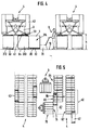
- the can carriers 6, 60, 61 with the cans 3 find their place on or under these textile machines 4 without having to fiddle with and maneuvering for a long time with the can carriers 6, 60, 61 if a can group 31, 310, 311 with empty cans 3 is to be exchanged as a complete unit for a can group 31, 310, 311 with filled cans 3, the sections 40 and the can carriers 6, 60, 61 are dimensioned in accordance with FIGS. 1 and 5 such that either a single can carrier 6, 60, 61 or an integer multiple thereof in an optimal manner at the same time in a second, third, fourth ... working position A 2 , A 3 , A 4 ... (Fig. 5) on or under the textile machine 4.
- the can carriers 6, 60, 61 and also the displacement device 20 of the line 2 are also of a size to the sections 40 of the sliver processing textile machine 4 - or vice versa, the sections 40 adapted to the standard size (as pallets) can carriers 6 ... - adapted.
- first a can carrier with empty cans 3 from the sliver processing Textile machine 4 fetched before another can carrier filled cans 3 can take the place of the first can carrier.
- two can carriers 66 and 67 provided with five cans 3 per section 40, but this is by no means interpret restrictively; it is easily possible, instead, pro Section 40 only one can carrier or three or more can carriers with one to place a different number of cans 3 per group of cans. This depends on the size of the can carrier and the type of sliver processing Textile machine 4 on which the cans 3 are housed for processing the slivers 30 Need to become.
- the open-end spinning machine is the one on which this one is concerned Description refers and which is shown in the drawings, only an example of a belt processing textile machine 4.
- Other belt processing Textile machines e.g. B. circular knitting machines, have no sections 40th such as the ring spinning or the rotor or other type of open-end spinning machine on. Even in such a case, it is beneficial to use the sliver processing or consuming textile machine 4 and the can carrier 4 dimensionally to coordinate with each other, even if the space available in circular fur knitting machines are cheaper than spinning machines or flyers, so that these circular knitting machines u. U. waived this mutual dimensional coordination can be.
- the can magazine 5 is designed so that a defined number, ie. H. an integer multiple, of jug carriers 66, 67 can be placed side by side.
- a defined parking space E storage position reserved so that the intended number of can carriers within the can magazine 5 can actually find space and not by inaccurate parking space is wasted by porters.
- the automatic transport device shown there is the Appendix 1
- a central control device 71 is provided, which via a control line 710 with the control device 21 of the (tape supplying) route 2, upper one Control line 711 with a control device 41 of the belt processing textile machine 4 and a control line 712 with the car 7 in terms of tax Connection is established.
- a further control line 713 is provided, which with another tape processing textile machine 4, not shown, in terms of tax can communicate.
- Control line "in the sense of the present invention is formed by a cable; wireless control connections, for example by radio, infrared etc. can also be used instead of cable connections.
- control lines 710, 711, 713 etc. give the central control device 71, which coordinates the work of the can car 7 or the can car 7, knowledge of how far the work on the individual components of the system 1 has progressed or how many can carriers 6 ... are provided for collection there, and can set corresponding priorities for the work of the car 7 or 7.
- the control device 71 defines transport routes and transport start times and gives its control commands to the suitable can car 7, which then drives the machine 2 or 4 or the can magazine 5. If only a single, self-contained path 70 is provided for a plurality of can wagons 7, a direction of rotation is defined for them, for example according to arrow f 5 .
- the path lengths that a car 7 has to travel through until it reaches the components to be operated or started by it depend on this direction of rotation, which is to be taken into account by the control device 71.
- a closed rail circuit not sufficient, especially if several belt processing textile machines 4 must be operated within the same system 1.
- the components to be started and operated are not all are arranged one behind the other within a closed path 70, but if this track 70 has branches 700, 701 etc., on which the can car 7 can leave the main rail circuit for further, not shown, in a parallel rail section 702 arranged system components such as further lines 2, further sliver processing textile machines 4 or can magazines 5 can be reached and operated.
- a self-propelled can car 7 this has a can carrier holder 72 for the can carrier 6, 60, 61, 66, 67, who has no other task to perform has to carry 31 as the complete can group.
- the can car 6, 60, 61, 66, 67 can therefore be very simple, so that even a commercially available Pallet with standard dimensions can perform this task (see Fig. 4 and 5).
- the Can car 7 in turn, of which only a few copies required and which are complex to set up, especially in automatic systems, do not need to remain on the individual components of Appendix 1.
- the cans 3 not on the route 2 and possibly also on each other component of the system 1 individually from a car 7 removed and on the route 2 and, if desired, on or in the band processing Textile machine 4 or the can magazine 5 provided or from there must be taken over again individually. Rather, the cans 3 remain all the time on the can carriers 6, 60, 61, 66, 67, so that otherwise for the individual reloading of the cans 3 is omitted and thus the time for reloading required time is reduced to a minimum.
- a monitoring device 42 in each of the sliver 30 (Band guard - see FIGS. 1 and 4), which uses a control line 420 with the control device 41 of the belt processing textile machine 4 is connected. If the sliver 30 fed to a spinning station D runs out or breaks, reports the monitoring device 42 immediately sends this to the control device 41.
- the monitoring device 42 can be designed differently. For example a can change (as a change of a complete, on a can carrier 6 ... can group 31 ...) can only be carried out if the slivers 30 of all cans 3 of this group of cans 31 ... expired or have been interrupted, a single, common monitoring device is sufficient 42 for the entire can group 31 .... In this fur there are Monitoring device 42 only then sends a signal to control device 41, when none of the spinning positions D assigned to this can group 31 ... are working , whereupon the control device 41 exchanges the can carrier 6 ... with the empty cans 3 against a can carrier 6 ... with filled cans 3 requests from the central control device 71.
- each spinning station D can also have a separate monitoring device 42 may be assigned so that each individual sliver 30 of this group of cans 31 ... monitored and its leakage or interruption registered and sent to the Control device 41 is reported.
- the control device 41 an adjustment device 410 may be assigned. With the help of this adjustment device 410 a value can be set for the number of non-working cans 3 on a can carrier 6 ... can group 31 ..., in which the Sliver 30 has run out or is interrupted, so that when this is reached Value, d. H. with a preset number of such registrations, one Function is triggered.
- such a function can already be used for Leakage or interruption of a single sliver 30 (but only at two or more fiber ribbons 30 up to the total number of this can group 31 delivered slivers 30 that have been processed or interrupted) to be triggered.
- an automatic transport device (automatically controlled can car 7) is a request signal to the Central control device 71 issued so that an exchange of the can carrier 6 ... is initiated against one with filled cans 3.
- the monitoring device 42 instead an acoustic or optical or a combined signal generated by an operator 9 the absence of this sliver 30 or sliver 30 indicates that this operator 9 carry out the exchange of the can carrier by hand can.
- the can car 79 can in turn be designed differently, for example have a similar can carrier receptacle 72 as that with the help 1 explained can car 7th
- a forklift 78 is used as a can truck, which picks up and carries through the can carrier 65, which is designed as a pallet Pumps "from the floor 10 so that the can carrier 65 can be brought to the desired location within the system 1.
- Fig. 4 it is shown that the belt processing textile machine 4 (here an open-end spinning machine) already two can carriers 63 and 64 with can groups 312 and 313 are located.
- the textile machine 4 has below the spinning positions D with the spinning units, not shown, such a clear height h, that a can carrier 63, 64 or 65 etc. fits here and also the slivers 30 can be fed to the spinning units unhindered. Furthermore there must be sufficient space for the automatic maintenance machines 43 to be unimpeded can drive along the textile machine 4.
- a gap that cannot be seen in FIG. 4 (second working position A 2 - see FIG. 5) below the textile machine 4 has previously arisen in that a forklift 78 has picked up a can carrier (not shown) with a group of cans with empty cans.
- An operator 9 has then moved up to a new can carrier 65 with a can group 314 with filled cans 3 and is just about to equip this second working position A 2 with the new complete can group 314.
- the operator 9 therefore guides the can carrier 65 with the help of the forklift 78 into this working position A 2 and lets the can carrier 65 down there, so that the forklift 78 can leave the textile machine 4 again without taking the can carrier 65 and the can group 314 carried by it.
- the can car 79 only a platform (not shown) on which the expediently by a standard pallet made of can carriers 6 ... is parked.
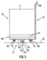
- the can carrier 6 either with the help of a separate transport medium, e.g. B. a can car 7, 79 or a forklift 78 or the like, by hand or automatically between the individual components to transport the system 1 or the can carrier 68 as an integrated To form part of the can car 73 (Fig. 2 and 3).
- This will help of its handle bar 730 as a whole between the individual components of the System 1 transported and as a whole with one and the same can group 315 on the individual components of Appendix 1 for those to be carried out there Work or storage deposited.
- the can car 73 (FIGS. 2 and 3) or 79 (FIG. 5) - regardless of whether the can carrier 6 ... is an integrated part thereof or not - has a chassis 74 with at least one pair of wheels 740, the common axis 743, or the two axes of the wheels 741, 742 of this pair of wheels 740 is or are oriented parallel to the longitudinal extension (double arrow f 6 ) of the can group 31.
- This common axle 743 does not need or the two axles (not shown) of the pair of wheels 740 do not need to be steerable, since the can wagons 73 and 79 can be maneuvered well even without the steerability of the wheels 741 and 742.
- the bearing (s) 744 for the axle (s) 743 is or are therefore rigidly connected to the can carriage 79 or to the can support 68 which is designed as an integral part of the can carriage 73. It is possible without difficulty to insert the can carrier 6, 60, 61, 63, 64, 65, 66 or 67 or the can car 73 with an integrated can carrier 68 into a can carrier receptacle 72 adapted to the can carrier 6 ... along the route 2 , a belt processing textile machine 4 or a can magazine 5 at least partially move in to transfer the can carrier 6 ... or the can carriage 73 by moving to the can carrier receptacle 72 and thus to the line 2, the belt processing textile machine 4 or the can magazine 5 .
- the can carrier receptacle 72 has two can carrier guides on both sides 720 on which the can carrier 6 ... or the can car 73 are parked becomes.
- the can carrier 6 etc. or the can car has 73 with respect to the group of cans arranged on it in the form of a row of cans 31, 310, 311, 312, 313, 314, 315 on the underside of skids 62 (see Fig. 4) with which he is in all or different components of Appendix 1 (including forklift 78 or can 7 or 79).
- the can carrier guides 720 in turn each have a roller conveyor 721 with rollers 722 to move the can carrier 6 ... or the can car 73 facilitate.
- Such a roller conveyor 721 is on the individual components of the Appendix 1, if desired also on the can wagon independent of the can carrier 6 ... 7 or 79 ... provided.
- a can wagon 73 that functions as a can carrier and that fits into the can carrier receptacle 72 to be maneuvered in must be positioned exactly to drive this into the can holder 72 without much effort to be able to perform.
- This wheel 75 or 76 or, if provided, these two wheels 75 and 76 has or each have a vertical pivot axis carried by the can car 73 750 or 760, so that the car 73 on the one hand by this leading or trailing wheel 75 or 76 or stabilized by these two wheels 75 and 76 and on the other hand, steering is possible without difficulty.
- a further improvement in the steerability of the car 73 can be Formation of the chassis 74 (pair of wheels 740 and wheels 75 and 76) according to FIG. 3 to reach.
- the axis has 743 or axes (not shown) of the pair of wheels 740 a greater distance from the floor 731 of the Can car 73 as the horizontal axes 751 and 761 of the wheels 75 and 76.
- the can car 73 assumes a stable end position when it is not on its pair of wheels 740 also rests on wheel 75 or 76 while in its unstable intermediate position with neither of these two wheels 75 and 76 in contact with the floor 10 arrives and is supported solely on the pair of wheels 740.
- the can car 73 is supported only unstable due to the non-steerable pair of wheels 740, which is why for the Transporting the car 73 from one component of the system 1 to the other always one of the other two steerable wheels 75 or 76 to support the Kannenwagens 73 is used.
- the can carrier 6... Or can carriage 73 is adequately secured in its position in or on the individual components of system 1 and (in the case of non-integrated design) on the can carriage 79 or 7 due to the friction . If a roller conveyor 721 is provided, it is generally also not to be expected that the can carrier 6... Or the can carriage 73 will leave its position within the can carrier receptacle 72. Nevertheless, there are further measures for locking the can carrier 6 ... in its working position A 1 (on route 2), A 2 , A 3 , A 4 ... (on the belt-processing textile machine 4), at parking space E (in the can magazine 5 ) or in relation to the transport medium (can car 7, 79 or forklift 78).
- the roller conveyor 721 can have an inclination (not shown) such that the can carrier (integrated or individual with the can carriage 73) receives a movement component which moves it into the can carrier receptacle 72 so that it moves to the end facing away from the operating side System comes to a suitable stop 724.
- the can carrier 68 at a suitable location for. B. according to FIGS. 2 and 3 on its side, has a recess 77 in which a locking device 8 can engage.
- the locking device 8 can be designed differently and automatically or be operable by an operator 9.
- the displacement device of the route 2 can be different be trained.
- the 1, is not designed as an endless belt or chain, but as a sledge or carriage, which is dimensioned such that it always only a single can carrier 6 ... and can take this with Progress of his work step by step from an initial position to an end position and then brought back to its original position.
- the locking device 8 is in the slide-shaped displacement device 24 is arranged.
- the locking device 8 has a two-armed, pivotally mounted locking lever 80, which by a tension spring 81 in contact with one arranged in the displacement device 24 Stop 84 is held and is acted upon such that he with his one Detent pawl 82 end in the path along the can carrier guide 720 in the can holder 72 to be moved 6 ... or Jug cart 73 protrudes.
- the other, free end 83 of the locking lever 80 protrudes over the outer contour of the slide or carriage-shaped displacement device 24 out of route 2.
- the can carrier 6 ... or the can car 73 with integrated can carrier 68 moved into the can carrier receptacle 72, he must the locking lever 80th Push out of the trajectory until it reaches the correct end position the can carrier 6 ... or the can carriage 73 into the recess 77 can intervene to the can carrier 6 ... or the can car 73 in his Secure position.
- the can carrier 6 ... remains in this secured position. or the can car 73, while the route 2, the cans 3 of the can carrier 6 ... or 68 fills, the displacement device 24 step by step Step past the filling station 23 of route 2.
- the displacement device brings 24 finally the free end 83 of the locking lever 80 for contact with the stationary stop 22, whereby the locking lever 80 is pivoted so that the Can carrier 6 ... is released and removed from the displacement device 24 can be. Has the can carrier 6 ... the displacement device 24 leave, it is moved back to its original position.
- Introducing a new can group 31 ... with the help of another can carrier 6 ... can be placed anywhere on the movement path of the displacement device 24 take place, d. H. both in their one and in their other end position as also in one of their intermediate positions.
- a locking device e.g. B. a stop 724 at the closed end of a can carrier receptacle 72, a locking device 8 and the friction of the can carrier guide 720. If with a can carrier equipped with a chassis (Can car 73) no locking device 8 is provided, then that Chassis can be disabled in any other way. this happens according to the embodiment described above, in that the can carrier 73rd by tilting around the pair of wheels 740 on the can carrier guide 720 and is pushed onto this, whereby the chassis 74 is lifted off the floor 10 becomes. In kinematic reversal, it is also conceivable among the components the system 1 lowerable plates or the like. To provide for locking, d. H.
- the locking device thus has a lifting device on, in the first case directly or indirectly (via the can car 73) the can carrier 6 ... acts to lift it off the floor 10 while in the other case, this merely pulls away the support for the chassis 74.
Landscapes
- Engineering & Computer Science (AREA)
- Mechanical Engineering (AREA)
- Textile Engineering (AREA)
- Spinning Or Twisting Of Yarns (AREA)
- Replacing, Conveying, And Pick-Finding For Filamentary Materials (AREA)
Applications Claiming Priority (2)
| Application Number | Priority Date | Filing Date | Title |
|---|---|---|---|
| DE19719765 | 1997-05-10 | ||
| DE19719765A DE19719765A1 (de) | 1997-05-10 | 1997-05-10 | Verfahren und Vorrichtung zum Transportieren einer Kannengruppe |
Publications (4)
| Publication Number | Publication Date |
|---|---|
| EP0877107A2 true EP0877107A2 (fr) | 1998-11-11 |
| EP0877107A3 EP0877107A3 (fr) | 1999-04-14 |
| EP0877107B1 EP0877107B1 (fr) | 2002-12-18 |
| EP0877107B2 EP0877107B2 (fr) | 2005-03-30 |
Family
ID=7829183
Family Applications (1)
| Application Number | Title | Priority Date | Filing Date |
|---|---|---|---|
| EP98105377A Expired - Lifetime EP0877107B2 (fr) | 1997-05-10 | 1998-03-25 | Procédé et appareil pour le transport d'un groupe de pots |
Country Status (4)
| Country | Link |
|---|---|
| US (2) | US6055792A (fr) |
| EP (1) | EP0877107B2 (fr) |
| CZ (1) | CZ137398A3 (fr) |
| DE (2) | DE19719765A1 (fr) |
Families Citing this family (7)
| Publication number | Priority date | Publication date | Assignee | Title |
|---|---|---|---|---|
| DE19953202A1 (de) * | 1999-11-05 | 2001-05-10 | Manfred Langen | Spinnkannentransporter |
| AU2003248600B8 (en) * | 2002-06-14 | 2008-12-11 | Joseph Lam Wei Chak | Layout and design of production facility |
| US8621786B2 (en) | 2003-02-13 | 2014-01-07 | Wei Chak Joseph Lam | Efficient layout and design of production facility |
| US8108989B2 (en) | 2007-06-28 | 2012-02-07 | Crown Equipment Corporation | Manufacturing cell and elements of the cell |
| DE102015102267A1 (de) * | 2015-02-18 | 2016-08-18 | Sipra Patententwicklungs- Und Beteiligungsgesellschaft Mbh | Bestückungsanordnung für eine Spinnstrickmaschine |
| DE102022111675A1 (de) | 2022-05-10 | 2023-11-16 | Trützschler Group SE | Selbstfahrendes Fahrzeug zum Transportieren eines Aufnahmebehälters für ein Faserband und Kannenvorrichtung mit einem Aufnahmebehälter |
| WO2023217671A1 (fr) | 2022-05-10 | 2023-11-16 | Trützschler Group SE | Dispositif de transport sans conducteur comprenant un véhicule à conduite autonome pour transporter un récipient de réception pour un ruban |
Family Cites Families (16)
| Publication number | Priority date | Publication date | Assignee | Title |
|---|---|---|---|---|
| GB333396A (en) † | 1929-08-12 | 1930-08-14 | Mackie & Sons Ltd J | Improvements relating to the delivery of slivers from textile machines into cans |
| DE1781030A1 (de) † | 1968-08-13 | 1971-06-03 | Tmm Research Ltd | Kannenwechseleinrichtung fuer einen Flyer und eine diesen mit Faserbaendern versorgende Strecke |
| PH13610A (en) † | 1973-08-22 | 1980-08-05 | Teijin Ltd | System for transporting a filament-bundle from a spinning process to a cussessive drawing process |
| DE3532172A1 (de) * | 1985-09-10 | 1987-03-12 | Truetzschler & Co | Vorrichtung zum automatischen transport mindestens einer kanne zwischen einer faserbandabliefernden spinnereimaschine und einer faserbandgespeisten spinnereimaschine |
| DE3734258A1 (de) * | 1987-10-09 | 1989-04-20 | Zinser Textilmaschinen Gmbh | Verfahren und vorrichtung zum zufuehren von kannen mit faserband zu einer spinnereimaschine |
| CH681632A5 (fr) * | 1990-02-21 | 1993-04-30 | Rieter Ag Maschf | |
| US5276947A (en) * | 1990-05-18 | 1994-01-11 | Schubert & Salzer Maschinenfabrik Ag | Device for the transportion of cans between machines or devices treating or processing fiber slivers |
| IT1246595B (it) * | 1991-04-12 | 1994-11-24 | Iginia Busisi | Procedimento ed impianto per l'alimentazione di filatoi |
| EP0513439A1 (fr) * | 1991-05-18 | 1992-11-19 | Tetra Laval Holdings & Finance SA | Dispositif de remplissage et fermeture d'emballages pour produits fluides |
| CZ283155B6 (cs) * | 1991-09-23 | 1998-01-14 | Rieter Elitex A.S. | Způsob přípravy vlákenného pramene mezi pramenovým a finálním strojem |
| DE4233357B4 (de) * | 1992-10-05 | 2005-09-22 | Rieter Ingolstadt Spinnereimaschinenbau Ag | Verfahren zum Wechseln und Vorrichtung zum Magazinieren und Wechseln von Spinnkannen |
| JP3490498B2 (ja) * | 1993-05-14 | 2004-01-26 | ツリュツラー ゲゼルシャフト ミット ベシュレンクテル ハフツング ウント コンパニー コマンディトゲゼルシャフト | 紡績機械で縦長断面のケンスにスライバを充填する装置 |
| US5634316A (en) * | 1994-04-02 | 1997-06-03 | Trutzschler Gmbh & Co. Kg | Method and apparatus for handling flat coiler cans before, during and after filling the cans by a sliver-producing textile machine |
| DE4428474A1 (de) * | 1994-08-11 | 1996-02-15 | Truetzschler Gmbh & Co Kg | Verfahren und Vorrichtung zum Ablegen eines Textilfaserbandes in einem Faserbandbehälter, insbesondere an einer Strecke |
| DE4435853A1 (de) * | 1994-10-07 | 1996-04-11 | Innovatex Materials Handling G | Transporter in der Textilindustrie |
| DE19525737A1 (de) * | 1995-07-14 | 1997-01-16 | Schlafhorst & Co W | Kannenspeicher für Rechteck-Spinnkannen an einer Kannenfüllstation |
-
1997
- 1997-05-10 DE DE19719765A patent/DE19719765A1/de not_active Withdrawn
-
1998
- 1998-03-25 EP EP98105377A patent/EP0877107B2/fr not_active Expired - Lifetime
- 1998-03-25 DE DE59806670T patent/DE59806670D1/de not_active Expired - Fee Related
- 1998-05-05 CZ CZ981373A patent/CZ137398A3/cs unknown
- 1998-05-05 US US09/073,231 patent/US6055792A/en not_active Expired - Fee Related
-
2000
- 2000-05-01 US US09/562,483 patent/US6233904B1/en not_active Expired - Fee Related
Also Published As
| Publication number | Publication date |
|---|---|
| EP0877107B1 (fr) | 2002-12-18 |
| DE59806670D1 (de) | 2003-01-30 |
| US6233904B1 (en) | 2001-05-22 |
| EP0877107A3 (fr) | 1999-04-14 |
| CZ137398A3 (cs) | 1998-11-11 |
| DE19719765A1 (de) | 1998-11-12 |
| US6055792A (en) | 2000-05-02 |
| EP0877107B2 (fr) | 2005-03-30 |
Similar Documents
| Publication | Publication Date | Title |
|---|---|---|
| EP0528907B1 (fr) | Procede et dispositif pour le transport de cannettes plates entre des machines ou des dipositifs servant a travailler ou a traiter des bandes de fibres | |
| EP0407703B1 (fr) | Procédé et dispositif pour stocker et déstocker des caissons contenant des matériaux en forme de bâton ou de plaque dans un magasin à rayonnage | |
| DE68909099T2 (de) | Vorrichtung zum automatischen Zuteilen von Vorgarn an Spinnmaschinen. | |
| DE4018088B4 (de) | Verfahren und Vorrichtung zum fortlaufenden Wechsel der Faserbandkannen in einem Maschinenverbund zwischen einer faserbandabliefernden Maschine und einer faserbandverbrauchenden Maschine | |
| EP0925246B1 (fr) | Procede pour le transport de rouleaux vers un changeur de rouleaux | |
| DE3538838A1 (de) | Vorrichtung zum liefern von auflaufspulen zu spulengattern | |
| EP0925248B1 (fr) | Installation pour l'insertion et l'enlevement automatiques de rouleaux | |
| EP0531905B1 (fr) | Dispositif pour transferer des tubes de bobine | |
| DE3928648A1 (de) | Anlage mit einer oder mehreren spinnmaschinen und mit wenigstens einem wechselwagen zum wechseln von kannen | |
| DD297132A5 (de) | Transporteinrichtung fuer wickel | |
| DE102006012484A1 (de) | Vorrichtung in einer Spinnerei zum Transportieren einer kannenlosen Faserbandpackung | |
| CH662586A5 (de) | Spinnanlage zur herstellung von garn aus vorgarn. | |
| EP0525447B1 (fr) | Chariot de transport de pots pour le remplacement automatique de pots | |
| DE4323726A1 (de) | Transportfahrzeug für Faserbandkannen | |
| EP0877107B1 (fr) | Procédé et appareil pour le transport d'un groupe de pots | |
| EP1098017A2 (fr) | Transporteur pour le transfert de pots de filature | |
| EP0198260B1 (fr) | Procédé et dispositif pour le transport et le stockage de bobines, par exemple pour l'alimentation des machines à filer | |
| DE2439769C3 (de) | Verfahren und Transportsystem zum zyklischen Transportieren von mit einem Faserband gefüllten Kannen | |
| DE4015938A1 (de) | Spinnereianlage | |
| DE19860475B4 (de) | Einrichtung zum Aufnehmen und Transportieren von Papierbahn-Restrollen für eine Rollenrotationsdruckmaschine | |
| EP0655093B2 (fr) | Procede et dispositif pour mettre des bidons en magasin | |
| DE10252174A1 (de) | Spinnkannen-Transportwagen | |
| EP0953535B1 (fr) | Procédé et appareil pour l'approvisionnement et le stockage de pots | |
| EP0855456B1 (fr) | Procédé et appareil pour transporter des bobines pleines de ruban de fibres respectivement des tubes vides pour le ruban de fibres | |
| DE4432634A1 (de) | Kannenlose Vorgarnhandhabung |
Legal Events
| Date | Code | Title | Description |
|---|---|---|---|
| PUAI | Public reference made under article 153(3) epc to a published international application that has entered the european phase |
Free format text: ORIGINAL CODE: 0009012 |
|
| AK | Designated contracting states |
Kind code of ref document: A2 Designated state(s): DE FR IT |
|
| AX | Request for extension of the european patent |
Free format text: AL;LT;LV;MK;RO;SI |
|
| PUAL | Search report despatched |
Free format text: ORIGINAL CODE: 0009013 |
|
| AK | Designated contracting states |
Kind code of ref document: A3 Designated state(s): AT BE CH DE DK ES FI FR GB GR IE IT LI LU MC NL PT SE |
|
| AX | Request for extension of the european patent |
Free format text: AL;LT;LV;MK;RO;SI |
|
| 17P | Request for examination filed |
Effective date: 19990724 |
|
| AKX | Designation fees paid |
Free format text: DE FR IT |
|
| 17Q | First examination report despatched |
Effective date: 20010710 |
|
| GRAG | Despatch of communication of intention to grant |
Free format text: ORIGINAL CODE: EPIDOS AGRA |
|
| GRAG | Despatch of communication of intention to grant |
Free format text: ORIGINAL CODE: EPIDOS AGRA |
|
| GRAH | Despatch of communication of intention to grant a patent |
Free format text: ORIGINAL CODE: EPIDOS IGRA |
|
| GRAH | Despatch of communication of intention to grant a patent |
Free format text: ORIGINAL CODE: EPIDOS IGRA |
|
| GRAA | (expected) grant |
Free format text: ORIGINAL CODE: 0009210 |
|
| AK | Designated contracting states |
Kind code of ref document: B1 Designated state(s): DE FR IT |
|
| PG25 | Lapsed in a contracting state [announced via postgrant information from national office to epo] |
Ref country code: FR Free format text: LAPSE BECAUSE OF FAILURE TO SUBMIT A TRANSLATION OF THE DESCRIPTION OR TO PAY THE FEE WITHIN THE PRESCRIBED TIME-LIMIT Effective date: 20021218 |
|
| REF | Corresponds to: |
Ref document number: 59806670 Country of ref document: DE Date of ref document: 20030130 Kind code of ref document: P Ref document number: 59806670 Country of ref document: DE Date of ref document: 20030130 |
|
| PLBQ | Unpublished change to opponent data |
Free format text: ORIGINAL CODE: EPIDOS OPPO |
|
| PLBI | Opposition filed |
Free format text: ORIGINAL CODE: 0009260 |
|
| 26 | Opposition filed |
Opponent name: TRUETZSCHLER GMBH & CO. KG Effective date: 20030820 |
|
| PLAX | Notice of opposition and request to file observation + time limit sent |
Free format text: ORIGINAL CODE: EPIDOSNOBS2 |
|
| EN | Fr: translation not filed | ||
| PLAX | Notice of opposition and request to file observation + time limit sent |
Free format text: ORIGINAL CODE: EPIDOSNOBS2 |
|
| PLBB | Reply of patent proprietor to notice(s) of opposition received |
Free format text: ORIGINAL CODE: EPIDOSNOBS3 |
|
| PUAH | Patent maintained in amended form |
Free format text: ORIGINAL CODE: 0009272 |
|
| STAA | Information on the status of an ep patent application or granted ep patent |
Free format text: STATUS: PATENT MAINTAINED AS AMENDED |
|
| 27A | Patent maintained in amended form |
Effective date: 20050330 |
|
| AK | Designated contracting states |
Kind code of ref document: B2 Designated state(s): DE FR IT |
|
| PGFP | Annual fee paid to national office [announced via postgrant information from national office to epo] |
Ref country code: IT Payment date: 20060331 Year of fee payment: 9 |
|
| EN | Fr: translation not filed | ||
| PGFP | Annual fee paid to national office [announced via postgrant information from national office to epo] |
Ref country code: DE Payment date: 20080415 Year of fee payment: 11 |
|
| PG25 | Lapsed in a contracting state [announced via postgrant information from national office to epo] |
Ref country code: IT Free format text: LAPSE BECAUSE OF NON-PAYMENT OF DUE FEES Effective date: 20070325 |
|
| PG25 | Lapsed in a contracting state [announced via postgrant information from national office to epo] |
Ref country code: DE Free format text: LAPSE BECAUSE OF NON-PAYMENT OF DUE FEES Effective date: 20091001 |