EP0877126A2 - Dispositif d'infiltration - Google Patents
Dispositif d'infiltration Download PDFInfo
- Publication number
- EP0877126A2 EP0877126A2 EP98105705A EP98105705A EP0877126A2 EP 0877126 A2 EP0877126 A2 EP 0877126A2 EP 98105705 A EP98105705 A EP 98105705A EP 98105705 A EP98105705 A EP 98105705A EP 0877126 A2 EP0877126 A2 EP 0877126A2
- Authority
- EP
- European Patent Office
- Prior art keywords
- infiltration device
- water
- shaft
- opening
- throttle element
- Prior art date
- Legal status (The legal status is an assumption and is not a legal conclusion. Google has not performed a legal analysis and makes no representation as to the accuracy of the status listed.)
- Granted
Links
- 230000008595 infiltration Effects 0.000 title claims description 20
- 238000001764 infiltration Methods 0.000 title claims description 20
- XLYOFNOQVPJJNP-UHFFFAOYSA-N water Substances O XLYOFNOQVPJJNP-UHFFFAOYSA-N 0.000 claims abstract description 35
- 238000007789 sealing Methods 0.000 claims 1
- 239000007788 liquid Substances 0.000 description 2
- 238000005259 measurement Methods 0.000 description 2
- 238000000034 method Methods 0.000 description 2
- 238000009825 accumulation Methods 0.000 description 1
- 238000004140 cleaning Methods 0.000 description 1
- 238000011109 contamination Methods 0.000 description 1
- 238000011010 flushing procedure Methods 0.000 description 1
- 238000009434 installation Methods 0.000 description 1
- 230000007257 malfunction Effects 0.000 description 1
- 230000000630 rising effect Effects 0.000 description 1
Images

Classifications
-
- E—FIXED CONSTRUCTIONS
- E03—WATER SUPPLY; SEWERAGE
- E03F—SEWERS; CESSPOOLS
- E03F1/00—Methods, systems, or installations for draining-off sewage or storm water
- E03F1/002—Methods, systems, or installations for draining-off sewage or storm water with disposal into the ground, e.g. via dry wells
-
- E—FIXED CONSTRUCTIONS
- E03—WATER SUPPLY; SEWERAGE
- E03B—INSTALLATIONS OR METHODS FOR OBTAINING, COLLECTING, OR DISTRIBUTING WATER
- E03B3/00—Methods or installations for obtaining or collecting drinking water or tap water
- E03B3/02—Methods or installations for obtaining or collecting drinking water or tap water from rain-water
-
- Y—GENERAL TAGGING OF NEW TECHNOLOGICAL DEVELOPMENTS; GENERAL TAGGING OF CROSS-SECTIONAL TECHNOLOGIES SPANNING OVER SEVERAL SECTIONS OF THE IPC; TECHNICAL SUBJECTS COVERED BY FORMER USPC CROSS-REFERENCE ART COLLECTIONS [XRACs] AND DIGESTS
- Y02—TECHNOLOGIES OR APPLICATIONS FOR MITIGATION OR ADAPTATION AGAINST CLIMATE CHANGE
- Y02A—TECHNOLOGIES FOR ADAPTATION TO CLIMATE CHANGE
- Y02A10/00—TECHNOLOGIES FOR ADAPTATION TO CLIMATE CHANGE at coastal zones; at river basins
- Y02A10/30—Flood prevention; Flood or storm water management, e.g. using flood barriers
-
- Y—GENERAL TAGGING OF NEW TECHNOLOGICAL DEVELOPMENTS; GENERAL TAGGING OF CROSS-SECTIONAL TECHNOLOGIES SPANNING OVER SEVERAL SECTIONS OF THE IPC; TECHNICAL SUBJECTS COVERED BY FORMER USPC CROSS-REFERENCE ART COLLECTIONS [XRACs] AND DIGESTS
- Y02—TECHNOLOGIES OR APPLICATIONS FOR MITIGATION OR ADAPTATION AGAINST CLIMATE CHANGE
- Y02A—TECHNOLOGIES FOR ADAPTATION TO CLIMATE CHANGE
- Y02A20/00—Water conservation; Efficient water supply; Efficient water use
- Y02A20/108—Rainwater harvesting
-
- Y—GENERAL TAGGING OF NEW TECHNOLOGICAL DEVELOPMENTS; GENERAL TAGGING OF CROSS-SECTIONAL TECHNOLOGIES SPANNING OVER SEVERAL SECTIONS OF THE IPC; TECHNICAL SUBJECTS COVERED BY FORMER USPC CROSS-REFERENCE ART COLLECTIONS [XRACs] AND DIGESTS
- Y02—TECHNOLOGIES OR APPLICATIONS FOR MITIGATION OR ADAPTATION AGAINST CLIMATE CHANGE
- Y02A—TECHNOLOGIES FOR ADAPTATION TO CLIMATE CHANGE
- Y02A20/00—Water conservation; Efficient water supply; Efficient water use
- Y02A20/40—Protecting water resources
Definitions
- the invention relates to an infiltration device for rainwater, consisting from a pipe socket with a water inlet arranged inside a shaft, a water drain located inside the shaft and a water overflow, the amount of water emerging through the water outlet through a throttle element is adjustable and wherein the water flowing through the throttle element through a Drain opening in the shaft can drain.
- a generic infiltration device is rainwater infiltration over a Trough-trench system with accumulation regulation.
- the trough trench is one example Aligned parallel to the road layout and provided with a drain connection.
- the The stowage regulator of the known prior art is installed in a shaft and has an inlet, an overflow and a rotary lobe, depending on the angular position releases a variable discharge cross-section for the rainwater drain.
- This Movable rotary lobes have been found to be disadvantageous in practical operation because through deposits in the drain water in a relatively short time baking the Rotary piston takes place and a malfunction of the entire system occurs.
- the actually released opening for the overflow water can not determine precisely, so that an exact measurement of the discharge capacity is not possible.
- an individual measurement of this molded part for each installation is i. d. R. required.
- a flushing of the entire manhole system, which for cleaning purposes in More or less large distances is required only through perfect opening and then realign the rotary lobe.
- this diaphragm slide of the throttle element through the movement mechanics over the entire cross-section to be released is movable.
- this diaphragm slide is one with an opening provided, flat component, which is slidably mounted in a guide link is advantageous, this guide is made up of two flat components, which on their two longitudinal edges and liquid-tightly connected to each other at the lower transverse edge are.
- the opening of the slit diaphragm is designed egg-shaped with the tip pointing upwards to the transverse wall.
- the throttle drain system is based on the structure of the prior art Technology and consists of a shaft pipe into which the water inlet from the connected trough-trench system opens. This water inlet is liquid-tight connected to the throttle shaft.
- This discharge throttle preferably inside the Shaft arranged, has an inlet, an overflow and a cross-section reducible Procedure. This process, which can be reduced in cross section, is carried out according to the invention by the throttle closure designed as an aperture slide.
- the aperture slider is infinitely adjustable via the movement mechanism or is interchangeable.
- the released cross-sectional area on the throttle can be on the movement mechanics defined. So that the drain donation, d. i.e. by the free passage of the throttle flow of water per unit of time, perfect be determined.
- the fine adjustment of the runoff donation can also take place in that the movement mechanism is designed as a non-rising spindle that has a Device can be adjusted continuously.
- the Throttle lock is set in defined stages via a locking mechanism and each with a lock or a similar locking device against unauthorized adjustment is secured.
- Another advantage of the diaphragm slide according to the invention is therein seen that the friction surfaces between the diaphragm slide and the guide link are kept low. This will cause the contamination to become stuck entire aperture-slide system avoided. Is z.
- the egg-shaped design of the opening of the diaphragm slide according to the invention enables correct dosing of the volume flow.
- the egg - shaped design of the opening of the Aperture slider is not mandatory. Rather, the aperture slider also have a circular opening or various smaller ones Opening culverts that one after the other in the clear cross section of the water drain can be inserted.
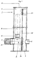
- Fig. 1 shows the shaft 1 with the connected drain pipe 2, which in turn with the trough-drainage system not shown here is connected.
- the drain pipe 2 can be connected to the discharge throttle 3 in a liquid-tight manner.
- the discharge throttle 3 has the connecting piece 31 for the seepage pipe 2, the water overflow 32 by a inserted tube 33 - shown in dashed lines - arbitrarily upwards into the lumen 11 of the Shaft 1 is extendable.
- the throttle element 5 is a movement mechanism 51, which with an actuating rod, spindle or a similar actuating element 52 with is connected to the throttle element 5, vertically movable in the illustration shown
- the shaft 1 can be closed with the shaft cover 12.
- the water outlet opening 6 is arranged through the shaft the throttle element 5 emerging water can leave the shaft.
- the water drain opening 6 can be designed as an arch, the water inlet opening for Bottom of the shaft 1 is directed. This prevents that in the event of a fault in the Shaft 1 harmful liquids, z. B. Light liquids in the receiving water can be delivered or penetrate into the trench.
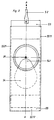
- FIG. 2 shows the diaphragm slide 53 of the throttle element 5 with the guide link 55 in top view.
- the diaphragm slide 53 is shown in a position in which the egg-shaped Opening 54 dips with its tip 541 into the clear cross-section 35 of the discharge throttle 3. In this position, only water from the outlet throttle 3 into the tip 541 Enter lumen 11 of shaft 1.
- the guide link 55 consists of two flat components 551, 552 (Fig. 3), which its two longitudinal edges 5511, 5521 and the lower transverse edge 5512 liquid-tight are interconnected.
- Fig. 3 shows the cross section through the representation in Fig. 2 along the line A-A. Same Components have been given the same names here.
Landscapes
- Engineering & Computer Science (AREA)
- Health & Medical Sciences (AREA)
- Life Sciences & Earth Sciences (AREA)
- Hydrology & Water Resources (AREA)
- Public Health (AREA)
- Water Supply & Treatment (AREA)
- Environmental & Geological Engineering (AREA)
- Separation By Low-Temperature Treatments (AREA)
- Electrical Discharge Machining, Electrochemical Machining, And Combined Machining (AREA)
- Infusion, Injection, And Reservoir Apparatuses (AREA)
- Devices For Use In Laboratory Experiments (AREA)
- Sewage (AREA)
- Sliding Valves (AREA)
- Nozzles (AREA)
- Glass Compositions (AREA)
- Centrifugal Separators (AREA)
- Fluid-Driven Valves (AREA)
Applications Claiming Priority (2)
| Application Number | Priority Date | Filing Date | Title |
|---|---|---|---|
| DE29708322U | 1997-05-09 | ||
| DE29708322U DE29708322U1 (de) | 1997-05-09 | 1997-05-09 | Versickerungsvorrichtung |
Publications (3)
| Publication Number | Publication Date |
|---|---|
| EP0877126A2 true EP0877126A2 (fr) | 1998-11-11 |
| EP0877126A3 EP0877126A3 (fr) | 1999-01-27 |
| EP0877126B1 EP0877126B1 (fr) | 2004-05-12 |
Family
ID=8040153
Family Applications (1)
| Application Number | Title | Priority Date | Filing Date |
|---|---|---|---|
| EP98105705A Expired - Lifetime EP0877126B1 (fr) | 1997-05-09 | 1998-03-28 | Dispositif d'infiltration |
Country Status (5)
| Country | Link |
|---|---|
| EP (1) | EP0877126B1 (fr) |
| AT (1) | ATE266777T1 (fr) |
| CZ (1) | CZ7813U1 (fr) |
| DE (2) | DE29708322U1 (fr) |
| PL (1) | PL326211A1 (fr) |
Cited By (3)
| Publication number | Priority date | Publication date | Assignee | Title |
|---|---|---|---|---|
| DE102004002745A1 (de) * | 2004-01-20 | 2005-08-04 | Lingen, Elena | Übergabeschacht |
| WO2015187074A1 (fr) * | 2014-06-05 | 2015-12-10 | Kjell Andersson | Puits d'eau pluviale |
| US12006676B2 (en) | 2018-05-11 | 2024-06-11 | Aco Ahlmann Se & Co. Kg | Drainage body unit, drainage body system and shaft element |
Families Citing this family (3)
| Publication number | Priority date | Publication date | Assignee | Title |
|---|---|---|---|---|
| DE29715802U1 (de) * | 1997-09-03 | 1997-10-23 | REHAU AG + Co., 95111 Rehau | Schluckbrunnen |
| DE29919821U1 (de) * | 1999-11-11 | 2000-01-20 | REHAU AG + Co., 95111 Rehau | Versickerungsvorrichtung |
| DE202006006098U1 (de) * | 2006-04-15 | 2007-08-30 | Rehau Ag + Co | Schachtanordnung |
Citations (1)
| Publication number | Priority date | Publication date | Assignee | Title |
|---|---|---|---|---|
| DE29516580U1 (de) | 1995-10-20 | 1995-12-07 | Rehau Ag + Co, 95111 Rehau | Versickerungsvorrichtung |
Family Cites Families (6)
| Publication number | Priority date | Publication date | Assignee | Title |
|---|---|---|---|---|
| DE2727955A1 (de) * | 1977-06-22 | 1979-01-18 | Nikolaus Blank | Steuerung fuer unterirdische be- und entwaesserungsanlagen |
| DE7801273U1 (de) * | 1978-01-18 | 1978-06-29 | Ernst Schmieding Gmbh & Co, 4600 Dortmund | Kanal- oder rinnenschieber |
| DE3240902C2 (de) * | 1982-11-05 | 1994-10-06 | Steinhardt Lothar | Abflußmengenregler |
| US4678367A (en) * | 1986-01-29 | 1987-07-07 | Warner James I | Riser assembly for a sub-surface irrigation and drainage system |
| GB2198322B (en) * | 1986-11-01 | 1990-10-17 | Raymond Lodge | Sports surface construction |
| DE29514845U1 (de) * | 1995-09-15 | 1995-11-23 | Porta Rohr Technik GmbH, 32457 Porta Westfalica | Anstauregelorgan |
-
1997
- 1997-05-09 DE DE29708322U patent/DE29708322U1/de not_active Expired - Lifetime
-
1998
- 1998-03-28 DE DE59811357T patent/DE59811357D1/de not_active Expired - Fee Related
- 1998-03-28 AT AT98105705T patent/ATE266777T1/de not_active IP Right Cessation
- 1998-03-28 EP EP98105705A patent/EP0877126B1/fr not_active Expired - Lifetime
- 1998-05-07 CZ CZ19988024U patent/CZ7813U1/cs not_active IP Right Cessation
- 1998-05-08 PL PL98326211A patent/PL326211A1/xx unknown
Patent Citations (1)
| Publication number | Priority date | Publication date | Assignee | Title |
|---|---|---|---|---|
| DE29516580U1 (de) | 1995-10-20 | 1995-12-07 | Rehau Ag + Co, 95111 Rehau | Versickerungsvorrichtung |
Cited By (4)
| Publication number | Priority date | Publication date | Assignee | Title |
|---|---|---|---|---|
| DE102004002745A1 (de) * | 2004-01-20 | 2005-08-04 | Lingen, Elena | Übergabeschacht |
| WO2015187074A1 (fr) * | 2014-06-05 | 2015-12-10 | Kjell Andersson | Puits d'eau pluviale |
| US12006676B2 (en) | 2018-05-11 | 2024-06-11 | Aco Ahlmann Se & Co. Kg | Drainage body unit, drainage body system and shaft element |
| EP3791027B1 (fr) * | 2018-05-11 | 2024-08-07 | ACO Ahlmann SE & Co. KG | Unité de rigole de corps de remplissage, système de rigole de corps de remplissage et éléments de regard |
Also Published As
| Publication number | Publication date |
|---|---|
| CZ7813U1 (cs) | 1998-09-14 |
| EP0877126B1 (fr) | 2004-05-12 |
| PL326211A1 (en) | 1998-11-23 |
| EP0877126A3 (fr) | 1999-01-27 |
| DE59811357D1 (de) | 2004-06-17 |
| DE29708322U1 (de) | 1997-07-10 |
| ATE266777T1 (de) | 2004-05-15 |
Similar Documents
| Publication | Publication Date | Title |
|---|---|---|
| DE2311840C2 (de) | Mischventil für zwei Fluidströmungen | |
| DE2847504A1 (de) | Mischkopf zum mischen von wenigstens zwei fliessfaehigen materialkomponenten | |
| EP0877126B1 (fr) | Dispositif d'infiltration | |
| EP0120988B2 (fr) | Installation de filtration se rinçant à contre-courant | |
| EP1707692B1 (fr) | Robinet pourvu d'un bec téléscopique | |
| DE29909979U1 (de) | Schwimmerventil für industrielle Flüssigkeiten | |
| EP1245258A2 (fr) | Dispositif de nettoyage, en particulier pour la filtration de liquides | |
| EP3705647B1 (fr) | Réservoir de chasse d'eau pourvu de soupape de remplissage | |
| DE3912436C2 (de) | Vorrichtung zum Regeln des Abflusses | |
| DE19629137A1 (de) | Steuereinrichtung für ein Fluid, wie Wasser | |
| CH716848A2 (de) | Becken mit Bodenablauf. | |
| DE2727955A1 (de) | Steuerung fuer unterirdische be- und entwaesserungsanlagen | |
| DE3432731A1 (de) | Thermostatisch gesteuerte unterputzarmatur | |
| DE2809825C2 (de) | Rückstauverschluß für Abwasserleitungen | |
| CH687048A5 (de) | Abflussregulator insbesondere fuer ein Regenwasser aufnehmendes Rueckhaltebecken. | |
| DE2347524B2 (de) | Selbsttaetig schliessendes mischventil mit einem mit zwei seitlichen wassereintrittsoeffnungen versehenen gehaeuse | |
| DE4137768C1 (en) | Automatic hoist with downwards open bell - has outlet tube, whose top end retains movably top-open float pot | |
| DE7730965U1 (de) | Hahn fuer spuelkaesten | |
| DE3908009A1 (de) | Sanitaerventil | |
| DE102004056565A1 (de) | Ventil für Sanitärarmaturen | |
| DE29516580U1 (de) | Versickerungsvorrichtung | |
| DE7914750U1 (de) | Abflussmengenregler fuer wasserspeicherbecken o.dgl. | |
| DE4412825A1 (de) | Dampfbügeleisen | |
| DE3108792C2 (de) | Ablaufeinrichtung für Abwasser mit einem Siphon und einer doppelten Rückstausicherung | |
| EP4375431A1 (fr) | Bassin avec bouche d'écoulement |
Legal Events
| Date | Code | Title | Description |
|---|---|---|---|
| PUAI | Public reference made under article 153(3) epc to a published international application that has entered the european phase |
Free format text: ORIGINAL CODE: 0009012 |
|
| AK | Designated contracting states |
Kind code of ref document: A2 Designated state(s): AT BE CH DE FR LI LU NL |
|
| AX | Request for extension of the european patent |
Free format text: AL;LT;LV;MK;RO;SI |
|
| PUAL | Search report despatched |
Free format text: ORIGINAL CODE: 0009013 |
|
| AK | Designated contracting states |
Kind code of ref document: A3 Designated state(s): AT BE CH DE DK ES FI FR GB GR IE IT LI LU MC NL PT SE |
|
| AX | Request for extension of the european patent |
Free format text: AL;LT;LV;MK;RO;SI |
|
| 17P | Request for examination filed |
Effective date: 19990212 |
|
| RIN1 | Information on inventor provided before grant (corrected) |
Inventor name: MUELLER, STEPHAN Inventor name: KANIA, GUIDO |
|
| AKX | Designation fees paid |
Free format text: AT BE CH DE FR LI LU NL |
|
| 17Q | First examination report despatched |
Effective date: 20020513 |
|
| GRAP | Despatch of communication of intention to grant a patent |
Free format text: ORIGINAL CODE: EPIDOSNIGR1 |
|
| GRAS | Grant fee paid |
Free format text: ORIGINAL CODE: EPIDOSNIGR3 |
|
| GRAA | (expected) grant |
Free format text: ORIGINAL CODE: 0009210 |
|
| AK | Designated contracting states |
Kind code of ref document: B1 Designated state(s): AT BE CH DE FR LI LU NL |
|
| PG25 | Lapsed in a contracting state [announced via postgrant information from national office to epo] |
Ref country code: NL Free format text: LAPSE BECAUSE OF FAILURE TO SUBMIT A TRANSLATION OF THE DESCRIPTION OR TO PAY THE FEE WITHIN THE PRESCRIBED TIME-LIMIT Effective date: 20040512 Ref country code: FR Free format text: LAPSE BECAUSE OF FAILURE TO SUBMIT A TRANSLATION OF THE DESCRIPTION OR TO PAY THE FEE WITHIN THE PRESCRIBED TIME-LIMIT Effective date: 20040512 |
|
| REG | Reference to a national code |
Ref country code: CH Ref legal event code: EP |
|
| REF | Corresponds to: |
Ref document number: 59811357 Country of ref document: DE Date of ref document: 20040617 Kind code of ref document: P |
|
| NLV1 | Nl: lapsed or annulled due to failure to fulfill the requirements of art. 29p and 29m of the patents act | ||
| PLBE | No opposition filed within time limit |
Free format text: ORIGINAL CODE: 0009261 |
|
| STAA | Information on the status of an ep patent application or granted ep patent |
Free format text: STATUS: NO OPPOSITION FILED WITHIN TIME LIMIT |
|
| PG25 | Lapsed in a contracting state [announced via postgrant information from national office to epo] |
Ref country code: LU Free format text: LAPSE BECAUSE OF NON-PAYMENT OF DUE FEES Effective date: 20050328 |
|
| PG25 | Lapsed in a contracting state [announced via postgrant information from national office to epo] |
Ref country code: BE Free format text: LAPSE BECAUSE OF NON-PAYMENT OF DUE FEES Effective date: 20050331 |
|
| 26N | No opposition filed |
Effective date: 20050215 |
|
| EN | Fr: translation not filed | ||
| BERE | Be: lapsed |
Owner name: *REHAU A.G. + CO. Effective date: 20050331 |
|
| BERE | Be: lapsed |
Owner name: *REHAU A.G. + CO. Effective date: 20050331 |
|
| PGFP | Annual fee paid to national office [announced via postgrant information from national office to epo] |
Ref country code: CH Payment date: 20080304 Year of fee payment: 11 |
|
| PGFP | Annual fee paid to national office [announced via postgrant information from national office to epo] |
Ref country code: AT Payment date: 20080303 Year of fee payment: 11 |
|
| PGFP | Annual fee paid to national office [announced via postgrant information from national office to epo] |
Ref country code: DE Payment date: 20080331 Year of fee payment: 11 |
|
| PG25 | Lapsed in a contracting state [announced via postgrant information from national office to epo] |
Ref country code: AT Free format text: LAPSE BECAUSE OF NON-PAYMENT OF DUE FEES Effective date: 20090328 |
|
| REG | Reference to a national code |
Ref country code: CH Ref legal event code: PL |
|
| PG25 | Lapsed in a contracting state [announced via postgrant information from national office to epo] |
Ref country code: LI Free format text: LAPSE BECAUSE OF NON-PAYMENT OF DUE FEES Effective date: 20090331 Ref country code: DE Free format text: LAPSE BECAUSE OF NON-PAYMENT OF DUE FEES Effective date: 20091001 Ref country code: CH Free format text: LAPSE BECAUSE OF NON-PAYMENT OF DUE FEES Effective date: 20090331 |