EP0877136A2 - Porte pour chambre froide, notmment porte coulissante, avec à l'exterieur un dispositif de verrouillage et avec à l'interieur un dispositif de déverrouillage de secours - Google Patents
Porte pour chambre froide, notmment porte coulissante, avec à l'exterieur un dispositif de verrouillage et avec à l'interieur un dispositif de déverrouillage de secours Download PDFInfo
- Publication number
- EP0877136A2 EP0877136A2 EP98108052A EP98108052A EP0877136A2 EP 0877136 A2 EP0877136 A2 EP 0877136A2 EP 98108052 A EP98108052 A EP 98108052A EP 98108052 A EP98108052 A EP 98108052A EP 0877136 A2 EP0877136 A2 EP 0877136A2
- Authority
- EP
- European Patent Office
- Prior art keywords
- door
- hole
- pin
- rooms according
- lock
- Prior art date
- Legal status (The legal status is an assumption and is not a legal conclusion. Google has not performed a legal analysis and makes no representation as to the accuracy of the status listed.)
- Granted
Links
- 230000008878 coupling Effects 0.000 claims abstract description 6
- 238000010168 coupling process Methods 0.000 claims abstract description 6
- 238000005859 coupling reaction Methods 0.000 claims abstract description 6
- 241001125879 Gobio Species 0.000 claims description 7
- 230000000903 blocking effect Effects 0.000 claims description 6
- 238000000034 method Methods 0.000 claims description 6
- 230000006835 compression Effects 0.000 claims description 4
- 238000007906 compression Methods 0.000 claims description 4
- 238000003780 insertion Methods 0.000 claims description 4
- 230000037431 insertion Effects 0.000 claims description 4
- 239000000463 material Substances 0.000 claims description 3
- 229910052751 metal Inorganic materials 0.000 claims description 2
- 239000002184 metal Substances 0.000 claims description 2
- 239000007787 solid Substances 0.000 claims description 2
- 238000007373 indentation Methods 0.000 claims 1
- 230000007246 mechanism Effects 0.000 description 5
- 238000004519 manufacturing process Methods 0.000 description 3
- 238000004321 preservation Methods 0.000 description 2
- 229910052782 aluminium Inorganic materials 0.000 description 1
- XAGFODPZIPBFFR-UHFFFAOYSA-N aluminium Chemical compound [Al] XAGFODPZIPBFFR-UHFFFAOYSA-N 0.000 description 1
- 235000013399 edible fruits Nutrition 0.000 description 1
- 239000011888 foil Substances 0.000 description 1
- 238000007710 freezing Methods 0.000 description 1
- 230000008014 freezing Effects 0.000 description 1
- 230000005484 gravity Effects 0.000 description 1
- 235000013372 meat Nutrition 0.000 description 1
- 238000003825 pressing Methods 0.000 description 1
Images


Classifications
-
- F—MECHANICAL ENGINEERING; LIGHTING; HEATING; WEAPONS; BLASTING
- F25—REFRIGERATION OR COOLING; COMBINED HEATING AND REFRIGERATION SYSTEMS; HEAT PUMP SYSTEMS; MANUFACTURE OR STORAGE OF ICE; LIQUEFACTION SOLIDIFICATION OF GASES
- F25D—REFRIGERATORS; COLD ROOMS; ICE-BOXES; COOLING OR FREEZING APPARATUS NOT OTHERWISE PROVIDED FOR
- F25D23/00—General constructional features
- F25D23/02—Doors; Covers
- F25D23/021—Sliding doors
-
- F—MECHANICAL ENGINEERING; LIGHTING; HEATING; WEAPONS; BLASTING
- F25—REFRIGERATION OR COOLING; COMBINED HEATING AND REFRIGERATION SYSTEMS; HEAT PUMP SYSTEMS; MANUFACTURE OR STORAGE OF ICE; LIQUEFACTION SOLIDIFICATION OF GASES
- F25D—REFRIGERATORS; COLD ROOMS; ICE-BOXES; COOLING OR FREEZING APPARATUS NOT OTHERWISE PROVIDED FOR
- F25D23/00—General constructional features
- F25D23/02—Doors; Covers
- F25D23/028—Details
Definitions
- refrigerator rooms of large dimensions both for fruits preservation and meat preservation and/or freezing, consist of a chamber with insulated walls, which may also be built into a masonry room.
- An opening to get access inside the refrigerating room is closed by a door that can be normally opened like a book or be sliding on guides.
- Said doors are generally closed externally by various kinds of locking devices.
- Locking devices can be realized to be used by anybody wanting to enter the refrigerating room or be equipped with a key for controlled access to the room.
- One part i.e. the door-lock, is assembled on the door external face and the other part on the fixed wall outside the room, near the relevant opening.
- This kind of locking is rather complex and expensive as it requires assembly of a number of parts as well as a substantially exact coupling of the part assembled on the door with the one assembled on the room wall.
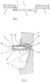
- Fig. 1 showing schematically a room section with the door in closed position according to the present invention
- number 1 indicates the opening to get access inside a room
- number 2 a sliding door
- number 3 the room walls defining the width of the opening
- number 4 a elements or means to lock sliding of the door 2 for its opening (the arrow indicates the opening direction of the door 2), to hinder access inside the room.
- the special configuration of the door-lock 5 and its position along a horizontal axis laying in the door plane 2 allows its insertion within the door thickness and without any element in sight on the door front face 2.
- Said hole 11 contains the non flanged end of the tube 6, whereas the hole 12 is supporting an end of the door-lock 5 with an interposed bushing 13 in plastic material, acting as a frictionless bearing the rotation of the door-lock during closing and/or opening operations of the door 2.
- Said first small block 14 has some mechanisms inside, known as such, which control a vertical movement of the pin 9 through a key.
- Said pin 22 locks the second cylindrical small block 18 in the tube 6 cooperating with a hole 23 on the tube 6 as represented in Fig. 4.
- Said pin 22 has an equal to and/or slightly smaller diameter than the width of the semicircular groove 21.
- Number 24 indicates a portion of the second cylindrical small block 18 with a smaller diameter to reduce the friction of the block 18 with the tube 6 when said small block 18 is rotating within the tube 6.
- said second cylindrical block 18 has a hole 25 of a truncated cone shape perpendicular to its horizontal axis and parallel to the pin axis 9 of the first small block 14. Said hole 25 is used to connect and control the locking means 4.
- Number 26 indicates the body of the locking means 4, which is substantially configured as a rectangle parallelepiped with a semicylindrical base 27 and open on its front (Fig. 3).
- said base 27 has a central upright hole 34 connecting the hole 28 with the higher portion of the body 26.
- Said upper wall 31 has an upright groove 32 of semicircular section on its center.
- Number 33 indicates a closing lid for the front part of the locking element.
- Said lid 33 is fastened with screws to the body 26 in a generally known manner.
- Number 37 indicates a round pin having a first part with a diameter equal to and/or slightly smaller than the diameter of the hole 34, whose end protrudes out of the body 26 through the hole 34 itself, a second central part with a diameter equal to and/or slightly smaller than the diameter of the hole 36, whose size is smaller compared with the hole 36, thus forming a step between the two parts, and a third part with a smaller diameter than the diameter of the second part, which protrudes out of the body 26 through the hole 36 and is used as a connection for a knob 38.
- Number 39 indicates a spiral spring inserted in the central part of the pin 37.
- Said spring 39 works under compression and is assembled preloaded; it is kept in position by the tooth resulting from the difference of diameter between the first and second part of the pin 37 and the internal surface of both the upper wall 31 of the body and the shorter side of the lid 33.
- Said spring 39 is provided to keep the truncated cone end of the first section of the pin 37 inserted in position in the truncated cone hole 25 of the cylinder 18, making the locking means 4 integral with the door-lock 5.
- the knob 42 is fastened by a threaded dowel, which is pressure screwed on the block 14 in a generally known manner.
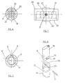
- Fig. 4 representing in section a detail of the locking elements in the horizontal direction of the door-lock 5 in the tube 6 fastened internally to the door 2
- number 6 indicates the flanged tube containing the door-lock 5
- number 18 the second cylindrical small block
- number 21 a semicircular throat on the small block
- number 23 the through-hole on the tube 6
- number 22 the locking pin of the small block 18 in the tube 6 and consequently locking of the door-lock 5.
- the pin 22 in the through-hole 23 and in the throat 21 will not let the door-lock to be extracted any more from the tube when the latter is inserted within the door thickness and fastened therein.
- Fig. 5 representing in section a detail of the locking system of the door-lock rotation
- number 6 indicates the tube where the door-lock 5 is inserted
- number 9 the rotation stop pin of the door-lock 5
- number 14 the small block carrying the control elements of the pin 9 and number 8 and 8' the holes engaging the pin 9.
- the figure represents the door-lock position during the door closing stage, i.e. with the locking means 4 in a horizontal position.
- Figs. 7 and 8 representing two traverse sections of the locking means 4
- number 26 indicates the body of the locking means 4
- numbers 29, 30, 30' and 31 the walls forming the upper part of the locking means 4
- number 33 the closing lid of the upper front section of the locking means 4.
- Number 36 indicates the hole formed by coupling the semicircular groove 32 of the wall 31 with the semicircular groove of the shorter lid wall 33.
- Number 34 indicates the through-hole for pin 37, numbers 40 and 41 the two bosses defining the run of the locking means 4.
- the body 26 of the locking means 4 is provided with bosses 40 and 41, to lock the movement of the locking means 4 when it reaches the closure and/or opening position, striking on the casing 10.
- the opening from inside the room can be obtained by pressing a button instead of pulling a knob.
- Said first portion of the pin 56 has a truncated cone configuration, whose dimensions are equal to those of the truncated come hole 25 of the small cylinder 18 where it will be inserted for the locking element 4 to become integral with the door-lock 5.
- the knob 63 is at distance from the body 46 since the second portion 61 of both sliding elements 59 and 59' where it is fastened to is protruding out of the body 46.
Landscapes
- Engineering & Computer Science (AREA)
- Chemical & Material Sciences (AREA)
- Combustion & Propulsion (AREA)
- Physics & Mathematics (AREA)
- Mechanical Engineering (AREA)
- Thermal Sciences (AREA)
- General Engineering & Computer Science (AREA)
- Refrigerator Housings (AREA)
- Closures For Containers (AREA)
- Lock And Its Accessories (AREA)
- Special Wing (AREA)
- Wing Frames And Configurations (AREA)
Applications Claiming Priority (2)
| Application Number | Priority Date | Filing Date | Title |
|---|---|---|---|
| IT97TO000384A IT1294382B1 (it) | 1997-05-05 | 1997-05-05 | Porte per celle refrigerate, in particolare porte scorrevoli, con chiusura esterna e con apertura interna di sicurezza. |
| ITTO970384 | 1997-05-05 |
Publications (3)
| Publication Number | Publication Date |
|---|---|
| EP0877136A2 true EP0877136A2 (fr) | 1998-11-11 |
| EP0877136A3 EP0877136A3 (fr) | 1999-11-03 |
| EP0877136B1 EP0877136B1 (fr) | 2004-03-10 |
Family
ID=11415696
Family Applications (1)
| Application Number | Title | Priority Date | Filing Date |
|---|---|---|---|
| EP98108052A Expired - Lifetime EP0877136B1 (fr) | 1997-05-05 | 1998-05-04 | Porte pour chambre froide, notmment porte coulissante, avec à l'exterieur un dispositif de verrouillage et avec à l'interieur un dispositif de déverrouillage de secours |
Country Status (4)
| Country | Link |
|---|---|
| EP (1) | EP0877136B1 (fr) |
| AT (1) | ATE261534T1 (fr) |
| DE (1) | DE69822247D1 (fr) |
| IT (1) | IT1294382B1 (fr) |
Cited By (3)
| Publication number | Priority date | Publication date | Assignee | Title |
|---|---|---|---|---|
| ES2177413A1 (es) * | 2000-08-10 | 2002-12-01 | Infraca S L | Palanca para apertura interior de puerta corrediza de camara frigorifica. |
| ES2179743A1 (es) * | 2000-08-10 | 2003-01-16 | Infraca S L | Palanca para apertura exterior de puerta corrediza de camara frigorifica. |
| US11905741B2 (en) | 2020-12-03 | 2024-02-20 | Haier Us Appliance Solutions, Inc. | Releasable locking mechanism for a refrigerated appliance |
Family Cites Families (7)
| Publication number | Priority date | Publication date | Assignee | Title |
|---|---|---|---|---|
| US2207568A (en) * | 1938-05-09 | 1940-07-09 | C V Hill & Company Inc | Latch mechanism for cold storage doors and the like |
| DE1096244B (de) * | 1959-04-14 | 1960-12-29 | Gust Kuhs Fa | Einlassschloss, insbesondere fuer Schiebetueren |
| US3115763A (en) * | 1961-05-18 | 1963-12-31 | Mosler Harbor Metal Products C | Lock for sliding doors |
| US3678716A (en) * | 1971-03-11 | 1972-07-25 | Westinghouse Electric Corp | Latch mechanism for refrigerators freezers and the like |
| DE2601671C3 (de) * | 1976-01-17 | 1982-02-18 | Gebr. Thome Kg, 7512 Rheinstetten | Verschließeinrichtung für Schiebetürschränke |
| US4061372A (en) * | 1976-04-05 | 1977-12-06 | Blomberg Glass | Secondary lock for sliding door or window |
| DE3019918A1 (de) * | 1980-05-24 | 1981-12-03 | Telewig Weigelt GmbH & Co KG, 4520 Melle | Vorrichtung zum verschliessen von schieetueren fuer kuehl-, gefrier- u.dgl. unter dem eigengewicht der schiebetuer hermetisch absperrbare raeume |
-
1997
- 1997-05-05 IT IT97TO000384A patent/IT1294382B1/it active IP Right Grant
-
1998
- 1998-05-04 EP EP98108052A patent/EP0877136B1/fr not_active Expired - Lifetime
- 1998-05-04 DE DE69822247T patent/DE69822247D1/de not_active Expired - Lifetime
- 1998-05-04 AT AT98108052T patent/ATE261534T1/de not_active IP Right Cessation
Cited By (3)
| Publication number | Priority date | Publication date | Assignee | Title |
|---|---|---|---|---|
| ES2177413A1 (es) * | 2000-08-10 | 2002-12-01 | Infraca S L | Palanca para apertura interior de puerta corrediza de camara frigorifica. |
| ES2179743A1 (es) * | 2000-08-10 | 2003-01-16 | Infraca S L | Palanca para apertura exterior de puerta corrediza de camara frigorifica. |
| US11905741B2 (en) | 2020-12-03 | 2024-02-20 | Haier Us Appliance Solutions, Inc. | Releasable locking mechanism for a refrigerated appliance |
Also Published As
| Publication number | Publication date |
|---|---|
| ITTO970384A0 (fr) | 1997-05-05 |
| DE69822247D1 (de) | 2004-04-15 |
| ATE261534T1 (de) | 2004-03-15 |
| EP0877136B1 (fr) | 2004-03-10 |
| IT1294382B1 (it) | 1999-03-24 |
| EP0877136A3 (fr) | 1999-11-03 |
| ITTO970384A1 (it) | 1998-11-05 |
Similar Documents
| Publication | Publication Date | Title |
|---|---|---|
| US5033282A (en) | Self-locking electronic lock | |
| US5020345A (en) | Self-locking electronic lock | |
| KR910002335B1 (ko) | 회전 댐퍼 | |
| US20200308871A1 (en) | Electronic lockbox | |
| US5136130A (en) | Locking actuator trigger button for electrical switch | |
| EP0540902A1 (fr) | Dispositif de fermeture pour un couvercle | |
| CN108571235B (zh) | 开锁机构、锁具及车辆 | |
| EP0877136B1 (fr) | Porte pour chambre froide, notmment porte coulissante, avec à l'exterieur un dispositif de verrouillage et avec à l'interieur un dispositif de déverrouillage de secours | |
| CN100523422C (zh) | 链式操作器外壳 | |
| CN112823232A (zh) | 闩锁 | |
| JPS63113290U (fr) | ||
| CN114922509B (zh) | 自动上锁锁体及自动上锁锁具 | |
| JP3628872B2 (ja) | 電動式ドア錠の駆動装置 | |
| KR101610932B1 (ko) | 푸시 앤 풀 타입 도어록 | |
| JP3577731B2 (ja) | キースイッチ | |
| KR0139218Y1 (ko) | 전자석을 이용한 도어 개폐장치 | |
| EP3546680B1 (fr) | Ensemble de fermeture avec dispositif de sécurité pour déverrouillage manuel de panneaux de porte ou tiroirs | |
| GB2250773A (en) | Automatic door look | |
| JP7441505B2 (ja) | 電気錠の操作ユニット | |
| KR200452305Y1 (ko) | 강제 잠금버튼 기능이 일체화된 손잡이를 갖는 문 잠금장치 | |
| KR100715507B1 (ko) | 도어 잠금장치 | |
| KR100882419B1 (ko) | 상, 하 잠금부를 갖는 미닫이문의 잠금부 동시 개폐장치 | |
| US3677219A (en) | Lock with key activating alarm mechanism | |
| EP0323580A1 (fr) | Dispositif pour ouvrir une porte verrouillées de l'interieur d'une chambre froide | |
| KR102720038B1 (ko) | 안심 도어락용 안전 캐치 |
Legal Events
| Date | Code | Title | Description |
|---|---|---|---|
| PUAI | Public reference made under article 153(3) epc to a published international application that has entered the european phase |
Free format text: ORIGINAL CODE: 0009012 |
|
| AK | Designated contracting states |
Kind code of ref document: A2 Designated state(s): AT BE DE DK ES FI FR GB GR IE IT LU NL PT SE |
|
| AX | Request for extension of the european patent |
Free format text: AL;LT;LV;MK;RO;SI |
|
| PUAL | Search report despatched |
Free format text: ORIGINAL CODE: 0009013 |
|
| AK | Designated contracting states |
Kind code of ref document: A3 Designated state(s): AT BE CH CY DE DK ES FI FR GB GR IE IT LI LU MC NL PT SE |
|
| AX | Request for extension of the european patent |
Free format text: AL;LT;LV;MK;RO;SI |
|
| 17P | Request for examination filed |
Effective date: 20000404 |
|
| AKX | Designation fees paid |
Free format text: AT BE DE DK ES FI FR GB GR IE IT LU NL PT SE |
|
| 17Q | First examination report despatched |
Effective date: 20020723 |
|
| REG | Reference to a national code |
Ref country code: GB Ref legal event code: FG4D |
|
| GRAH | Despatch of communication of intention to grant a patent |
Free format text: ORIGINAL CODE: EPIDOS IGRA |
|
| GRAS | Grant fee paid |
Free format text: ORIGINAL CODE: EPIDOSNIGR3 |
|
| GRAA | (expected) grant |
Free format text: ORIGINAL CODE: 0009210 |
|
| AK | Designated contracting states |
Kind code of ref document: B1 Designated state(s): AT BE DE DK ES FI FR GB GR IE IT LU NL PT SE |
|
| PG25 | Lapsed in a contracting state [announced via postgrant information from national office to epo] |
Ref country code: NL Free format text: LAPSE BECAUSE OF FAILURE TO SUBMIT A TRANSLATION OF THE DESCRIPTION OR TO PAY THE FEE WITHIN THE PRESCRIBED TIME-LIMIT Effective date: 20040310 Ref country code: IT Free format text: LAPSE BECAUSE OF FAILURE TO SUBMIT A TRANSLATION OF THE DESCRIPTION OR TO PAY THE FEE WITHIN THE PRESCRIBED TIME-LIMIT;WARNING: LAPSES OF ITALIAN PATENTS WITH EFFECTIVE DATE BEFORE 2007 MAY HAVE OCCURRED AT ANY TIME BEFORE 2007. THE CORRECT EFFECTIVE DATE MAY BE DIFFERENT FROM THE ONE RECORDED. Effective date: 20040310 Ref country code: FR Free format text: LAPSE BECAUSE OF FAILURE TO SUBMIT A TRANSLATION OF THE DESCRIPTION OR TO PAY THE FEE WITHIN THE PRESCRIBED TIME-LIMIT Effective date: 20040310 Ref country code: FI Free format text: LAPSE BECAUSE OF FAILURE TO SUBMIT A TRANSLATION OF THE DESCRIPTION OR TO PAY THE FEE WITHIN THE PRESCRIBED TIME-LIMIT Effective date: 20040310 Ref country code: BE Free format text: LAPSE BECAUSE OF FAILURE TO SUBMIT A TRANSLATION OF THE DESCRIPTION OR TO PAY THE FEE WITHIN THE PRESCRIBED TIME-LIMIT Effective date: 20040310 Ref country code: AT Free format text: LAPSE BECAUSE OF FAILURE TO SUBMIT A TRANSLATION OF THE DESCRIPTION OR TO PAY THE FEE WITHIN THE PRESCRIBED TIME-LIMIT Effective date: 20040310 |
|
| RAP2 | Party data changed (patent owner data changed or rights of a patent transferred) |
Owner name: M.T.H. MANIFATTURE TECNOLEGNO HARTZ S.R.L. |
|
| REG | Reference to a national code |
Ref country code: IE Ref legal event code: FG4D |
|
| REF | Corresponds to: |
Ref document number: 69822247 Country of ref document: DE Date of ref document: 20040415 Kind code of ref document: P |
|
| PG25 | Lapsed in a contracting state [announced via postgrant information from national office to epo] |
Ref country code: LU Free format text: LAPSE BECAUSE OF NON-PAYMENT OF DUE FEES Effective date: 20040504 Ref country code: IE Free format text: LAPSE BECAUSE OF NON-PAYMENT OF DUE FEES Effective date: 20040504 |
|
| NLT2 | Nl: modifications (of names), taken from the european patent patent bulletin |
Owner name: M.T.H. MANIFATTURE TECNOLEGNO HARTZ S.R.L. |
|
| PG25 | Lapsed in a contracting state [announced via postgrant information from national office to epo] |
Ref country code: SE Free format text: LAPSE BECAUSE OF FAILURE TO SUBMIT A TRANSLATION OF THE DESCRIPTION OR TO PAY THE FEE WITHIN THE PRESCRIBED TIME-LIMIT Effective date: 20040610 Ref country code: GR Free format text: LAPSE BECAUSE OF FAILURE TO SUBMIT A TRANSLATION OF THE DESCRIPTION OR TO PAY THE FEE WITHIN THE PRESCRIBED TIME-LIMIT Effective date: 20040610 Ref country code: GB Free format text: LAPSE BECAUSE OF NON-PAYMENT OF DUE FEES Effective date: 20040610 Ref country code: DK Free format text: LAPSE BECAUSE OF FAILURE TO SUBMIT A TRANSLATION OF THE DESCRIPTION OR TO PAY THE FEE WITHIN THE PRESCRIBED TIME-LIMIT Effective date: 20040610 |
|
| PG25 | Lapsed in a contracting state [announced via postgrant information from national office to epo] |
Ref country code: DE Free format text: LAPSE BECAUSE OF FAILURE TO SUBMIT A TRANSLATION OF THE DESCRIPTION OR TO PAY THE FEE WITHIN THE PRESCRIBED TIME-LIMIT Effective date: 20040612 |
|
| PG25 | Lapsed in a contracting state [announced via postgrant information from national office to epo] |
Ref country code: ES Free format text: LAPSE BECAUSE OF FAILURE TO SUBMIT A TRANSLATION OF THE DESCRIPTION OR TO PAY THE FEE WITHIN THE PRESCRIBED TIME-LIMIT Effective date: 20040621 |
|
| NLV1 | Nl: lapsed or annulled due to failure to fulfill the requirements of art. 29p and 29m of the patents act | ||
| PLBE | No opposition filed within time limit |
Free format text: ORIGINAL CODE: 0009261 |
|
| STAA | Information on the status of an ep patent application or granted ep patent |
Free format text: STATUS: NO OPPOSITION FILED WITHIN TIME LIMIT |
|
| GBPC | Gb: european patent ceased through non-payment of renewal fee |
Effective date: 20040610 |
|
| REG | Reference to a national code |
Ref country code: IE Ref legal event code: MM4A |
|
| EN | Fr: translation not filed | ||
| 26N | No opposition filed |
Effective date: 20041213 |
|
| PG25 | Lapsed in a contracting state [announced via postgrant information from national office to epo] |
Ref country code: PT Free format text: LAPSE BECAUSE OF NON-PAYMENT OF DUE FEES Effective date: 20040810 |