EP0877174A1 - Articulation verrouillable - Google Patents
Articulation verrouillable Download PDFInfo
- Publication number
- EP0877174A1 EP0877174A1 EP97303179A EP97303179A EP0877174A1 EP 0877174 A1 EP0877174 A1 EP 0877174A1 EP 97303179 A EP97303179 A EP 97303179A EP 97303179 A EP97303179 A EP 97303179A EP 0877174 A1 EP0877174 A1 EP 0877174A1
- Authority
- EP
- European Patent Office
- Prior art keywords
- shaft
- elbow
- movable
- constraint
- elbows
- Prior art date
- Legal status (The legal status is an assumption and is not a legal conclusion. Google has not performed a legal analysis and makes no representation as to the accuracy of the status listed.)
- Withdrawn
Links
- 210000002310 elbow joint Anatomy 0.000 claims abstract description 39
- 230000000717 retained effect Effects 0.000 claims abstract description 11
- 238000004519 manufacturing process Methods 0.000 description 2
- 239000004744 fabric Substances 0.000 description 1
- 238000000034 method Methods 0.000 description 1
Images


Classifications
-
- F—MECHANICAL ENGINEERING; LIGHTING; HEATING; WEAPONS; BLASTING
- F16—ENGINEERING ELEMENTS AND UNITS; GENERAL MEASURES FOR PRODUCING AND MAINTAINING EFFECTIVE FUNCTIONING OF MACHINES OR INSTALLATIONS; THERMAL INSULATION IN GENERAL
- F16C—SHAFTS; FLEXIBLE SHAFTS; ELEMENTS OR CRANKSHAFT MECHANISMS; ROTARY BODIES OTHER THAN GEARING ELEMENTS; BEARINGS
- F16C11/00—Pivots; Pivotal connections
- F16C11/04—Pivotal connections
- F16C11/10—Arrangements for locking
Definitions
- the present invention relates to an elbow joint assembly more particularly relates to a two dimenssional adjustable elbow joint assembly which comprises a shaft and two elbow joints mounted on two opposite ends of the shaft each elbow joint comprising a fixed elbow mounted on the shaft and prohibited from rotary motion relative to it and two movable elbows turned about the shaft relative to the fixed elbow in a plane perpendicular to the shaft and fixed at the desired angle by two constraint blocks by means of the control of two cam levers.
- Elbow joints are intensively used in furniture and mechanical devices such as cloth racks, baby carts, sunshades, chairs, antenna stands, etc., for permitting parts of devices to be adjusted to different angles.
- Regular elbow joints are commonly complicated in structure, and comprised of a big number of parts, therefore they are expensive to manufacture and inconvenient to operate.
- an elbow joint assembly which is simple in structure and inexpensive to manufacture. It is another object of the present invention to provide an elbow joint assembly which is easy to operate.
- an elbow joint assembly is provided comprised of a hollow shaft a screw rod inserted through the shaft two cap nuts respectively threaded onto the screw rods outside the shaft two elbow joints retained on a shaft at two opposite ends around the shaft and separated by two sets of stop rods, which are respectively connected to a locating block and a holding-down bolt in a holding-down nut at two opposite sides in parallel to the shaft.
- Each elbow joint comprises a fixed elbow having a barrel raised from the periphery and fixed to a locating rod of a mechanism, two movable elbows turned about the shat and having a respective barrel raised from the periphery and holding a respective rod two constraint blocks mounted on the shaft and forced to hold down the movable elbows and the fixed elbow in between the movable elbows, two spring elements mounted around the shaft between the movable elbows and the constraint blocks to force them apart; and two levers respectively pivoted to the shaft and turned between a first position in which the constraint blocks are forced into engagement with the movable elbows, causing the movable elbows and the fixed elbow to be firmly retained in position, and a second position in which the constraint blocks are released from the movable elbows, for permitting the movable elbows to be respectively turned about the shaft to the desired angle.
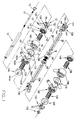
- an elbow joint assembly in accordance with the present invention is generally comprised of a hollow, polygonal shaft 10 , a screw rod 11 inserted into the shaft 10 , a first cap nut 12 and a second cap nut 12A respectively threaded onto two opposite ends of the screw rod 11 outside the shall 10, a locating block 18 mounted around the shaft 10 and having a polygonal center through hole 181 which receives the shaft 10 in such a manner that the locating block 18 is allowed to be moved axially along the shaft 10 but prohibited from rotary motion relative to the shaft 10, a hollow holding-down bol t 19 mounted around the shaft 10 and having a polygonal center through hole 191 which receives the shaft 10 in such a manner that the holding-down bolt 19 is allowed to be moved axially along the shaft 10 but prohibited from rotary motion relative to the shaft 10 , a holding-down nut 19A , a holding-down nut 19A threaded onto the holding-down bolt 19 and stopped at one side of the locating block
- the first elbow joint A comprises a first cam lever 13, a second cam lever 13A, a first constraint block 14, a second constraint block 14A, a first spring element 15, a second spring element 15A, a first movable elbow 16, a second movable elbow 16A, and a fixed elbow 17.
- the fixed elbow 17 is mounted around the shaft 10 and retained between the first movable elbow 16 and the second movable elbow 16A, having a polygonal center through hole 171 which receives the shaft 10 in such a manner that the fixed elbow 17 is allowed to be moved axially along the shaft 10 but prohibited from rotary motion relative to the shaft 10, a first extension tube 173 and a second extension tube 174 respectively raised from two opposite ends around the polygonal center through hole 171, and a locating barrel 172 raised from the periphery and adapted for securing to a locating rod of a mechanism.
- the first movable elbow 16 and the second movable elbow 16A are respectively mounted on the first extension tube 173 and second extension tube 174 of the fixed elbow 17 around the shaft 10, having a respective circular center through hole 161 or 161A which receives the extension tube 173 or 174 in such a manner that the movable elbow 16 or 16A is allowed to be moved axially along the extension tube 173 or 174 and turned about it, a respective barrel 162 or 162A extended from the periphery for holding a rod, permitting the rod to be turned with the movable elbow 16 or 16A in a plane perpendicular to the shaft, and a toothed portion 163 or 163A at an outer side.
- the first spring element 15 and the second spring element 15A are respectively mounted around the shaft 10 and retained between the movable elbows 16;16A and the constraint blocks 14;14A to force them apart.
- the first constraint block 14 and the second constraint block 14A are respectively mounted around the shaft 10 and forced by the first cam lever 13 and the second cam lever 13A into engagement with the first movable elbow 16 and the second movable elbow 16A, having each a polygonal center through hole 141 or 141A which receives the shaft 10 in such a manner that the constraint block 14 or 14A is allowed to be moved axially along the shaft 10 but prohibited from rotary motion relative to the shaft 10, and a toothed portion 142 or 142A at an inner side forced into engagement with the toothed portion 163 or 163A of the movable elbow 16 or 16A.
- the first lever 13 and the second leve r 13A are respectively mounted around the shaft 10 and controlled to force the constraint blocks 14;14A into engagement with the movable elbows 16;16A, causing the fixed elbow 17 to be firmly retained in between the movable elbows 16;16A.
- Each cam lever 13 or 13A comprises a head 131 or 131A defining a polygonal center through hole 132 or 132A which receives the shalt 10 in such a manner that the cam lever 13 or 13A is allowed to be moved axially along the shaft 10 but prohibited from rotary motion relative to the shaft 10, a hand grip 133 or 133A extended from the head 131 or 131 A and two cams 134 or 134A bilaterally raised from the head 131 or 131A and stopped at the constraint block 14 or 14A.
- the second elbow B is comprised of a first cam lever 13B, a second cam lever 13C, a first constraint block 14B, a second constraint block 14C , a first spring element 15B, a second spring element 15C, a first movable elbow 16B, a second movable elbow 16C, and a fixed elbow 17A.
- first cam lever 13B a second cam lever 13C
- first constraint block 14B a first constraint block 14B
- a second constraint block 14C a first spring element 15B
- a second spring element 15C a first movable elbow 16B
- a second movable elbow 16C a fixed elbow 17A.
- Figures 3A and 3B are side views of the second elbow joint B, and figure 3C is a sectional view of Figure 3B .
- the locating barrel 172A of the fixed elbow 17A is secured to a support rod 4, the barrels 162B;162C of the movable elbows 16B;16C are secured to rods 30A;30.
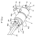
- Figure 4 shows an alternate form of the present invention, in which the locating block 18 is fixedly secured to the shaft 10' by for example a tightening lip screw, to fix the elbow joint A in place.
Landscapes
- Engineering & Computer Science (AREA)
- General Engineering & Computer Science (AREA)
- Mechanical Engineering (AREA)
- Mutual Connection Of Rods And Tubes (AREA)
Priority Applications (1)
| Application Number | Priority Date | Filing Date | Title |
|---|---|---|---|
| EP97303179A EP0877174A1 (fr) | 1997-05-09 | 1997-05-09 | Articulation verrouillable |
Applications Claiming Priority (1)
| Application Number | Priority Date | Filing Date | Title |
|---|---|---|---|
| EP97303179A EP0877174A1 (fr) | 1997-05-09 | 1997-05-09 | Articulation verrouillable |
Publications (1)
| Publication Number | Publication Date |
|---|---|
| EP0877174A1 true EP0877174A1 (fr) | 1998-11-11 |
Family
ID=8229323
Family Applications (1)
| Application Number | Title | Priority Date | Filing Date |
|---|---|---|---|
| EP97303179A Withdrawn EP0877174A1 (fr) | 1997-05-09 | 1997-05-09 | Articulation verrouillable |
Country Status (1)
| Country | Link |
|---|---|
| EP (1) | EP0877174A1 (fr) |
Cited By (1)
| Publication number | Priority date | Publication date | Assignee | Title |
|---|---|---|---|---|
| WO2005018369A1 (fr) * | 2003-08-22 | 2005-03-03 | Glatz Ag | Bras pour un parasol a bras libre, fixe a un mat de façon pivotante |
Citations (3)
| Publication number | Priority date | Publication date | Assignee | Title |
|---|---|---|---|---|
| FR2359686A1 (fr) * | 1976-07-27 | 1978-02-24 | Concord Meccanica Re Gi Srl | Manche reglable pour tondeuses a gazon et appareils similaires |
| GB2212555A (en) * | 1987-11-17 | 1989-07-26 | Britax Restmor Ltd | Clamping pivot |
| EP0702162A2 (fr) * | 1994-09-13 | 1996-03-20 | Yang-Ting Liu | Dispositif d'accouplement réglable |
-
1997
- 1997-05-09 EP EP97303179A patent/EP0877174A1/fr not_active Withdrawn
Patent Citations (3)
| Publication number | Priority date | Publication date | Assignee | Title |
|---|---|---|---|---|
| FR2359686A1 (fr) * | 1976-07-27 | 1978-02-24 | Concord Meccanica Re Gi Srl | Manche reglable pour tondeuses a gazon et appareils similaires |
| GB2212555A (en) * | 1987-11-17 | 1989-07-26 | Britax Restmor Ltd | Clamping pivot |
| EP0702162A2 (fr) * | 1994-09-13 | 1996-03-20 | Yang-Ting Liu | Dispositif d'accouplement réglable |
Cited By (3)
| Publication number | Priority date | Publication date | Assignee | Title |
|---|---|---|---|---|
| WO2005018369A1 (fr) * | 2003-08-22 | 2005-03-03 | Glatz Ag | Bras pour un parasol a bras libre, fixe a un mat de façon pivotante |
| US7398790B2 (en) | 2003-08-22 | 2008-07-15 | Glatz Ag | Extension arm for a free arm parasol, pivotably arranged on a carrier |
| AU2004266051B2 (en) * | 2003-08-22 | 2008-08-21 | Glatz Ag | Extension arm for a free arm parasol, pivotably arranged on a carrier |
Similar Documents
| Publication | Publication Date | Title |
|---|---|---|
| US5433551A (en) | Telescoping rod assembly | |
| US5827005A (en) | Elbow joint assembly | |
| US5419221A (en) | Indexable head ratchet wrench | |
| US4531855A (en) | Adjustable arm | |
| US5673925A (en) | Quick release skewer system | |
| EP1236007B1 (fr) | Trepied ameliore, en particulier pour usage optique et photographique | |
| US5163339A (en) | Bicycle auxiliary handle assembly | |
| US5799371A (en) | Pivoting joint | |
| US8096212B2 (en) | Two-section tool joint | |
| WO2003068028A1 (fr) | Appareil de support de clavier monte sur un accoudoir | |
| US5915784A (en) | Adjustable seat assembly | |
| JPH04503396A (ja) | 高速ナット | |
| US5074448A (en) | Golf cart score board and handlebar angular position adjusting structure | |
| JPH0792190B2 (ja) | 改良されたクランプ | |
| US5483732A (en) | Variable C-shaped retaining ring pliers | |
| US4405107A (en) | Clamp system for telescoping tubes | |
| US5328370A (en) | Dental tool assembly | |
| CA2139525C (fr) | Accouplement reglable | |
| GB2212555A (en) | Clamping pivot | |
| EP2527668B1 (fr) | Détecteur de touche pour la pêche connecté à un support de type "buzz bar" au moyen d'un dispositif de fixation | |
| WO2003004343A1 (fr) | Barres de guidon pliantes pour bicyclette pliable | |
| US4562985A (en) | Pan head | |
| US9995429B2 (en) | Fastening structure based on ratchet mesh | |
| US20140326839A1 (en) | Support for positioning an article in a free standing manner | |
| WO2017037751A1 (fr) | Mécanisme de support pour appuie-tête de fauteuil roulant |
Legal Events
| Date | Code | Title | Description |
|---|---|---|---|
| PUAI | Public reference made under article 153(3) epc to a published international application that has entered the european phase |
Free format text: ORIGINAL CODE: 0009012 |
|
| AK | Designated contracting states |
Kind code of ref document: A1 Designated state(s): AT BE CH DE DK ES FI FR GB GR IE IT LI LU |
|
| AX | Request for extension of the european patent |
Free format text: AL;LT;LV;RO;SI |
|
| AKX | Designation fees paid | ||
| RBV | Designated contracting states (corrected) |
Designated state(s): AT BE CH DE DK ES FI FR GB GR IE IT LI LU |
|
| RBV | Designated contracting states (corrected) |
Designated state(s): AT BE CH DE DK ES FI FR GB IT LI LU NL SE |
|
| STAA | Information on the status of an ep patent application or granted ep patent |
Free format text: STATUS: THE APPLICATION IS DEEMED TO BE WITHDRAWN |
|
| 18D | Application deemed to be withdrawn |
Effective date: 19990512 |