EP0877191B1 - Manchon d'accouplement pour un tuyau avec une gaine protectrice pour câbles électriques à soulagement de tension - Google Patents
Manchon d'accouplement pour un tuyau avec une gaine protectrice pour câbles électriques à soulagement de tension Download PDFInfo
- Publication number
- EP0877191B1 EP0877191B1 EP98108222A EP98108222A EP0877191B1 EP 0877191 B1 EP0877191 B1 EP 0877191B1 EP 98108222 A EP98108222 A EP 98108222A EP 98108222 A EP98108222 A EP 98108222A EP 0877191 B1 EP0877191 B1 EP 0877191B1
- Authority
- EP
- European Patent Office
- Prior art keywords
- box part
- collar
- protective sleeve
- slot
- suction tube
- Prior art date
- Legal status (The legal status is an assumption and is not a legal conclusion. Google has not performed a legal analysis and makes no representation as to the accuracy of the status listed.)
- Expired - Lifetime
Links
- 230000001681 protective effect Effects 0.000 title claims description 16
- 239000004020 conductor Substances 0.000 title claims description 7
- 230000008878 coupling Effects 0.000 title 1
- 238000010168 coupling process Methods 0.000 title 1
- 238000005859 coupling reaction Methods 0.000 title 1
- 238000000465 moulding Methods 0.000 claims description 7
- 230000007704 transition Effects 0.000 claims description 2
- 238000011144 upstream manufacturing Methods 0.000 claims 1
- 239000000463 material Substances 0.000 description 4
- 238000003780 insertion Methods 0.000 description 2
- 230000037431 insertion Effects 0.000 description 2
- 230000015572 biosynthetic process Effects 0.000 description 1
- 238000002347 injection Methods 0.000 description 1
- 239000007924 injection Substances 0.000 description 1
- 238000004519 manufacturing process Methods 0.000 description 1
- 238000000034 method Methods 0.000 description 1
Images
Classifications
-
- F—MECHANICAL ENGINEERING; LIGHTING; HEATING; WEAPONS; BLASTING
- F16—ENGINEERING ELEMENTS AND UNITS; GENERAL MEASURES FOR PRODUCING AND MAINTAINING EFFECTIVE FUNCTIONING OF MACHINES OR INSTALLATIONS; THERMAL INSULATION IN GENERAL
- F16L—PIPES; JOINTS OR FITTINGS FOR PIPES; SUPPORTS FOR PIPES, CABLES OR PROTECTIVE TUBING; MEANS FOR THERMAL INSULATION IN GENERAL
- F16L7/00—Supporting pipes or cables inside other pipes or sleeves, e.g. for enabling pipes or cables to be inserted or withdrawn from under roads or railways without interruption of traffic
-
- H—ELECTRICITY
- H02—GENERATION; CONVERSION OR DISTRIBUTION OF ELECTRIC POWER
- H02G—INSTALLATION OF ELECTRIC CABLES OR LINES, OR OF COMBINED OPTICAL AND ELECTRIC CABLES OR LINES
- H02G3/00—Installations of electric cables or lines or protective tubing therefor in or on buildings, equivalent structures or vehicles
- H02G3/02—Details
- H02G3/06—Joints for connecting lengths of protective tubing or channels, to each other or to casings, e.g. to distribution boxes; Ensuring electrical continuity in the joint
-
- H—ELECTRICITY
- H02—GENERATION; CONVERSION OR DISTRIBUTION OF ELECTRIC POWER
- H02G—INSTALLATION OF ELECTRIC CABLES OR LINES, OR OF COMBINED OPTICAL AND ELECTRIC CABLES OR LINES
- H02G3/00—Installations of electric cables or lines or protective tubing therefor in or on buildings, equivalent structures or vehicles
- H02G3/02—Details
- H02G3/06—Joints for connecting lengths of protective tubing or channels, to each other or to casings, e.g. to distribution boxes; Ensuring electrical continuity in the joint
- H02G3/0616—Joints for connecting tubing to casing
- H02G3/0691—Fixing tubing to casing by auxiliary means co-operating with indentations of the tubing, e.g. with tubing-convolutions
Definitions
- the invention relates to a connecting sleeve for a with a protective cover for strain-relieved electrical conductor provided hose according to the preamble of the claim 1.
- the protective cover consists of a round cross section Plastic hose.
- band-shaped strain relief elements inserted. These are made of material that is injected into the groove easily connects the material of the first sleeve part.
- the second sleeve part consists of the same plastic as the first sleeve part and is in its intended position through the plastic injected into the groove with the first sleeve part connected.
- the protective cover is at its end near the groove by a Plug closed, which is formed on the inside of the first sleeve part.
- the object of the invention is the connecting sleeve according to the preamble of the claim 1 so that for setting the strain relief element in the first Socket part and the connection of the two socket parts make an injection process unnecessary is.
- the object is achieved by the in the characterizing part of Claim 1 specified training solved.
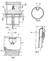
- a first socket part with 1 (FIG. 1) and a second socket part with 2 (Fig. 2).
- the two sleeve parts 1, 2 form a connecting sleeve for one Suction hose 3 (Fig. 3), which can be used for example as a vacuum cleaner hose.
- the parts 1 to 3 are combined so that the suction hose 3 in the second Sleeve part 2 engages and the first sleeve part 1 both in the second sleeve part 2 and also in the suction hose 3, the helical outside, not designated Has wave crests and wave valleys, engages.
- a protective cover 4 (Fig. 3) attached for strain-relieved electrical conductors.
- the protective cover 4 has example shown a circular cross section.
- the first sleeve part 1 contains a recess in which a strain relief element 5 (Fig. 1) is set.
- the depression is designed as an annular groove 6.
- the flanks of the slot 7 go into a tubular formation 10 (FIGS. 2 and 4) which, like the slot 7, is open at the insertion end of the first sleeve part 1. On hers opposite end, the molding 10 is closed.
- the molding 10 serves to accommodate the protective cover 4 in its intended position.
- the closure of the Forming 10 is possible in two ways.
- the wall of the molding 10 can be the second Bund 9 be raised. This applies in the event that the strain relief element 5 and possibly the electrical conductors from the protective cover 4 into the annular groove 6 are.
- the strain relief element 5 and the electrical in Fig. 4 Head not shown.
- FIG. 4 A second possibility of closing the molding 10 is also shown in FIG. 4 seen.
- the molding 10 extends here behind an opening 15 in the Wall of the first sleeve part 1 and is there on the wall of the first sleeve part 1 pulled up.
- the opening is in the example shown between the mouth and one fourth collar 19 of the first sleeve part 1 is provided.
- This arrangement enables it lead out in Fig. 1, 16 designated electrical conductor from the first sleeve part 1.
- the strain relief element 5, however, is through the slot 7 inserted into the annular groove 6.
- the strain relief element 5 encompasses the bottom of the annular groove 6 like a loop. Their free ends 5a run through the slot 7 in the direction of the protective cover 4, as in Fig. 1, in connection with Fig. 2, can be seen (see also arrow 17).
- the first sleeve part 1 engages in the second sleeve part 2 so far until the second sleeve part 2 abuts a third collar 18, which is therefore a Stop for the insertion depth of the first sleeve part 1 in the second sleeve part 2 forms.
- the second sleeve part 2 is provided with an inner groove 2a. This is arranged that the second collar 9 engages in a form-fitting manner when the second sleeve part 2 on third collar 18 of the first sleeve part 1 abuts.
- the suction hose 3 has a helically extending outer surface Wave crests and wave valleys. On the inner surface of the second sleeve part 2 at least one thread 20 is formed for screwing in the suction hose 3 (Fig. 3).
Landscapes
- Engineering & Computer Science (AREA)
- Architecture (AREA)
- Civil Engineering (AREA)
- Structural Engineering (AREA)
- General Engineering & Computer Science (AREA)
- Mechanical Engineering (AREA)
- Electric Vacuum Cleaner (AREA)
- Details Of Indoor Wiring (AREA)
- Insulating Bodies (AREA)
- Processing Of Terminals (AREA)
- Connections Effected By Soldering, Adhesion, Or Permanent Deformation (AREA)
- Cable Accessories (AREA)
Claims (6)
- Manchon de raccordement constitué par une première partie de manchon (1) et par une deuxième partie de manchon (2) pour un tuyau d'aspiration pourvu d'une gaine de protection (4) pour un conducteur électrique à soulagement de tension, présentant les éléments suivants :a) la gaine de protection (4) est fixée sur la surface enveloppe intérieure du tuyau d'aspiration (3) dans lequel s'engage partiellement la première partie de manchon (1),b) dans la première partie de manchon (1) est prévu un renfoncement qui est une gorge s'étendant transversalement à l'axe de la première partie de manchon et dans laquelle est immobilisé un élément de soulagement de tension (5) sorti hors de la gaine de protection (4),c) la deuxième partie de manchon (2) entourant le tuyau d'aspiration (3) recouvre le renfoncement,d) la première partie de manchon (1) et la deuxième partie de manchon (2) sont reliées l'une à l'autre,
caractérisé par les caractéristiques suivantes :e) le renfoncement pour l'élément de soulagement de tension (5) est une gorge annulaire (6),f) depuis l'extrémité d'emmanchement de la première partie de manchon (1) part une fente (7) axiale qui traverse une première collerette (8) formant une paroi de la gorge annulaire (6) et qui s'étend jusqu'à une deuxième collerette (9) qui forme l'autre paroi de la gorge annulaire (6),g) les flancs de fente se transforment en une conformation (10) tubulaire réalisée pour recevoir l'extrémité associée de la gaine de protection (4), laquelle est ouverte vers l'extrémité ouverte de la fente (7) et fermée à l'extrémité opposée, de sorte qu'un tronçon formant une boucle, de l'élément de soulagement de traction (5), entoure le fond de la gorge annulaire (6) tandis que les extrémités libres (Sa) de la boucle sont passées à travers la fente (7) jusque dans la gaine de protection (4). - Manchon de raccordement selon la revendication 1, caractérisé en ce que les extrémités libres (5a) de la boucle sont nouées au passage depuis le fond annulaire jusque dans la fente (7).
- Manchon de raccordement selon l'une ou l'autre des revendications 1 et 2, caractérisé en ce que le tuyau d'aspiration (3) présente sur sa surface enveloppe extérieure des sommets et des creux ondulés de forme hélicoïdale, et en ce que sur la surface enveloppe intérieure de la deuxième partie de manchon (2) est formé au moins un pas de vis (20) pour visser le tuyau d'aspiration (3).
- Manchon de raccordement selon l'une des revendications 1 à 3, caractérisé en ce que la deuxième partie de manchon (2) présente à proximité de son extrémité libre une gorge intérieure (2a) pour l'engagement par coopération de formes de la deuxième collerette (9).
- Manchon de raccordement selon l'une des revendications 1 à 4, caractérisé en ce qu'une troisième collerette (18) agencée devant la deuxième collerette (9) forme une butée pour la face frontale libre de la deuxième partie de manchon (2).
- Manchon de raccordement selon l'une des revendications 1 à 5, caractérisé en ce que la conformation (10) tubulaire s'étend dans l'enveloppe de la première partie de manchon (1) jusqu'à une ouverture (15) située entre l'embouchure de la première partie de manchon (1) et une quatrième collerette (19) et n'est fermée que derrière cette ouverture (15), et en ce que le conducteur électrique (16) est guidé depuis l'extrémité associée de la gaine de protection (4) jusqu'à l'ouverture (15) et est ensuite sorti hors de celle-ci.
Applications Claiming Priority (2)
| Application Number | Priority Date | Filing Date | Title |
|---|---|---|---|
| DE29708274U | 1997-05-07 | ||
| DE29708274U DE29708274U1 (de) | 1997-05-07 | 1997-05-07 | Anschlußmuffe für einen mit einer Schutzhülle für zugentlastete elektrische Leiter versehenen Schlauch |
Publications (3)
| Publication Number | Publication Date |
|---|---|
| EP0877191A2 EP0877191A2 (fr) | 1998-11-11 |
| EP0877191A3 EP0877191A3 (fr) | 2000-02-23 |
| EP0877191B1 true EP0877191B1 (fr) | 2003-09-17 |
Family
ID=8040112
Family Applications (1)
| Application Number | Title | Priority Date | Filing Date |
|---|---|---|---|
| EP98108222A Expired - Lifetime EP0877191B1 (fr) | 1997-05-07 | 1998-05-06 | Manchon d'accouplement pour un tuyau avec une gaine protectrice pour câbles électriques à soulagement de tension |
Country Status (4)
| Country | Link |
|---|---|
| US (1) | US6087595A (fr) |
| EP (1) | EP0877191B1 (fr) |
| DE (2) | DE29708274U1 (fr) |
| ES (1) | ES2207767T3 (fr) |
Families Citing this family (6)
| Publication number | Priority date | Publication date | Assignee | Title |
|---|---|---|---|---|
| DE20001357U1 (de) | 2000-01-26 | 2000-04-20 | Truplast Kunststofftechnik GmbH, 35428 Langgöns | Anschlussmuffe für einen mit einer Schutzhülle für zugentlastete elektrische Leiter versehenen Saugschlauch |
| US6322386B1 (en) | 2000-09-12 | 2001-11-27 | The Jpm Company | Connector boot with integral latch release |
| DE20114936U1 (de) * | 2001-09-10 | 2001-11-15 | Truplast Kunststofftechnik GmbH, 35428 Langgöns | Staubsaugerschlauch mit Anschlußmuffe |
| DE20114935U1 (de) * | 2001-09-10 | 2001-12-13 | Truplast Kunststofftechnik GmbH, 35428 Langgöns | Staubsaugerschlauch mit einer Anschlußmuffe |
| US6983767B2 (en) | 2002-11-27 | 2006-01-10 | Action Coupling And Equipment, Inc. | Sleeve for a hose |
| US9131815B2 (en) | 2011-11-07 | 2015-09-15 | Mark Genoa | Vacuum cleaner hose assembly connector |
Family Cites Families (12)
| Publication number | Priority date | Publication date | Assignee | Title |
|---|---|---|---|---|
| US4162370A (en) * | 1977-06-24 | 1979-07-24 | Automation Industries, Inc. | Current carrying hose assembly |
| US5288946A (en) * | 1992-06-18 | 1994-02-22 | Minnesota Mining And Manufacturing Company | Strain relief device and closure |
| DE4406197C2 (de) * | 1994-02-25 | 1996-10-24 | Daimler Benz Aerospace Airbus | Anschlußelement zur variablen Verlegung und zum Schutz von Leitungen |
| JP2785714B2 (ja) * | 1994-09-08 | 1998-08-13 | 住友電装株式会社 | シール用ゴム栓の固定構造 |
| DE4441478A1 (de) * | 1994-11-22 | 1996-05-23 | Murrplastik Systemtechnik Gmbh | Tülle |
| DE29507806U1 (de) * | 1995-05-11 | 1995-08-24 | Techno-Chemie Kessler & Co GmbH, 61184 Karben | Schlauch mit wenigstens einem zugentlasteten Energieleiter |
| JP2946296B2 (ja) * | 1995-12-06 | 1999-09-06 | 矢崎総業株式会社 | サイレンサー付グロメット及びその取付構造 |
| KR970032728A (ko) * | 1995-12-29 | 1997-07-22 | 배순훈 | 진공청소기의 회전호스 손잡이구조 |
| US5599202A (en) * | 1996-01-22 | 1997-02-04 | Electrical Wiring Device Company, Inc. | Strain relief electrical connector |
| BE1010676A3 (nl) * | 1996-10-10 | 1998-11-03 | Plastiflex Europ N V | Werkwijze en inrichting voor het vervaardigen van een soepele slangencombinatie. |
| BE1010689A3 (nl) * | 1996-10-15 | 1998-12-01 | Plastiflex Europ N V | Werkwijze voor het aanbrengen van een trekontlasting in een slang. |
| US5921784A (en) * | 1997-05-08 | 1999-07-13 | Framatome Connectors Usa Inc. | High speed card edge connector with tubular shared ground contact |
-
1997
- 1997-05-07 DE DE29708274U patent/DE29708274U1/de not_active Expired - Lifetime
-
1998
- 1998-05-06 EP EP98108222A patent/EP0877191B1/fr not_active Expired - Lifetime
- 1998-05-06 ES ES98108222T patent/ES2207767T3/es not_active Expired - Lifetime
- 1998-05-06 DE DE59809613T patent/DE59809613D1/de not_active Expired - Lifetime
- 1998-05-07 US US09/074,441 patent/US6087595A/en not_active Expired - Lifetime
Also Published As
| Publication number | Publication date |
|---|---|
| DE29708274U1 (de) | 1997-07-10 |
| US6087595A (en) | 2000-07-11 |
| EP0877191A2 (fr) | 1998-11-11 |
| ES2207767T3 (es) | 2004-06-01 |
| EP0877191A3 (fr) | 2000-02-23 |
| DE59809613D1 (de) | 2003-10-23 |
Similar Documents
| Publication | Publication Date | Title |
|---|---|---|
| DE2828893C2 (de) | Rohrverbinder für Kabelschutzrohre | |
| DE3925245C2 (de) | Kuppelbarer Schlauch sowie Verfahren zu seiner Herstellung | |
| EP0268869B1 (fr) | Dispositif à tuyau protecteur en matériau synthétique pour conduites | |
| DE69316453T2 (de) | Versiegelter elektrischer Stecker und Verfahren zu seiner Herstellung | |
| DE3101558A1 (de) | Vorrichtung zum halten von kabeln, leitungen, schlaeuchen oder dergleichen gegenstaende | |
| DE4037889A1 (de) | Handgriff fuer einen staubsauger | |
| DE7800585U1 (de) | Staubsaugerschlauch | |
| EP0318636B1 (fr) | Tuyau flexible | |
| DE19747959A1 (de) | Steckverbindung | |
| EP0877191B1 (fr) | Manchon d'accouplement pour un tuyau avec une gaine protectrice pour câbles électriques à soulagement de tension | |
| EP3218972A1 (fr) | Dispositif en forme de tube ondulé pour la réception de conduites et procédé de fabrication d'un tel dispositif en forme de tube ondulé | |
| EP1120878B1 (fr) | Manchon d'accouplement pour un tuyau d'aspiration flexible avec une gaine protectrice pour câbles électriques à soulagement de tension | |
| EP4268335A1 (fr) | Bouchon destiné à être fixé sur des conduites et d'autres éléments allongés | |
| EP3583664A1 (fr) | Protection contre le pliage de câbles préfabriqués | |
| EP1956149A1 (fr) | Tuyau, en particulier tuyau d'arrosage, avec enrobage par extrusion | |
| DE4134260C2 (de) | Hutmutter mit Knickschutz | |
| DE4125426C2 (de) | Anschlußstück für einen von einem profilierten gewendelten Metallband umgebenen Kunststoffschlauch | |
| DE20013601U1 (de) | Staubsaugerschlauch mit einer inneren Schutzhülle für elektrische Leiter | |
| DE3509231A1 (de) | Schlauch- bzw. rohranschluss | |
| EP1262704B1 (fr) | Manchon de raccord de tubes multi-canaux | |
| DE3426579C2 (fr) | ||
| DE69800799T2 (de) | Flüssigkeitdichte Kupplung für Gehäuse für elektrische Installation | |
| DE20001358U1 (de) | Anschlussmuffe für einen mit einer Schutzhülle für zugentlastete elektrische Leiter versehenen Saugschlauch | |
| EP0886356A2 (fr) | Conduit annelé aiguillé | |
| DE29510461U1 (de) | Schutzrohr gegen Marderverbiß |
Legal Events
| Date | Code | Title | Description |
|---|---|---|---|
| PUAI | Public reference made under article 153(3) epc to a published international application that has entered the european phase |
Free format text: ORIGINAL CODE: 0009012 |
|
| 17P | Request for examination filed |
Effective date: 19980506 |
|
| AK | Designated contracting states |
Kind code of ref document: A2 Designated state(s): DE ES FR GB IT NL SE |
|
| AX | Request for extension of the european patent |
Free format text: AL;LT;LV;MK;RO;SI |
|
| PUAL | Search report despatched |
Free format text: ORIGINAL CODE: 0009013 |
|
| AK | Designated contracting states |
Kind code of ref document: A3 Designated state(s): AT BE CH CY DE DK ES FI FR GB GR IE IT LI LU MC NL PT SE |
|
| AX | Request for extension of the european patent |
Free format text: AL;LT;LV;MK;RO;SI |
|
| AKX | Designation fees paid |
Free format text: DE ES FR GB IT NL SE |
|
| 17Q | First examination report despatched |
Effective date: 20020424 |
|
| GRAH | Despatch of communication of intention to grant a patent |
Free format text: ORIGINAL CODE: EPIDOS IGRA |
|
| GRAS | Grant fee paid |
Free format text: ORIGINAL CODE: EPIDOSNIGR3 |
|
| GRAA | (expected) grant |
Free format text: ORIGINAL CODE: 0009210 |
|
| AK | Designated contracting states |
Kind code of ref document: B1 Designated state(s): DE ES FR GB IT NL SE |
|
| REG | Reference to a national code |
Ref country code: GB Ref legal event code: FG4D Free format text: NOT ENGLISH |
|
| REG | Reference to a national code |
Ref country code: SE Ref legal event code: TRGR |
|
| REF | Corresponds to: |
Ref document number: 59809613 Country of ref document: DE Date of ref document: 20031023 Kind code of ref document: P |
|
| GBT | Gb: translation of ep patent filed (gb section 77(6)(a)/1977) |
Effective date: 20031111 |
|
| REG | Reference to a national code |
Ref country code: ES Ref legal event code: FG2A Ref document number: 2207767 Country of ref document: ES Kind code of ref document: T3 |
|
| ET | Fr: translation filed | ||
| PLBE | No opposition filed within time limit |
Free format text: ORIGINAL CODE: 0009261 |
|
| STAA | Information on the status of an ep patent application or granted ep patent |
Free format text: STATUS: NO OPPOSITION FILED WITHIN TIME LIMIT |
|
| 26N | No opposition filed |
Effective date: 20040618 |
|
| PGFP | Annual fee paid to national office [announced via postgrant information from national office to epo] |
Ref country code: FR Payment date: 20080213 Year of fee payment: 11 |
|
| PGFP | Annual fee paid to national office [announced via postgrant information from national office to epo] |
Ref country code: SE Payment date: 20080519 Year of fee payment: 11 Ref country code: NL Payment date: 20080516 Year of fee payment: 11 |
|
| PGFP | Annual fee paid to national office [announced via postgrant information from national office to epo] |
Ref country code: GB Payment date: 20080514 Year of fee payment: 11 |
|
| GBPC | Gb: european patent ceased through non-payment of renewal fee |
Effective date: 20090506 |
|
| NLV4 | Nl: lapsed or anulled due to non-payment of the annual fee |
Effective date: 20091201 |
|
| PG25 | Lapsed in a contracting state [announced via postgrant information from national office to epo] |
Ref country code: NL Free format text: LAPSE BECAUSE OF NON-PAYMENT OF DUE FEES Effective date: 20091201 |
|
| REG | Reference to a national code |
Ref country code: FR Ref legal event code: ST Effective date: 20100129 |
|
| PG25 | Lapsed in a contracting state [announced via postgrant information from national office to epo] |
Ref country code: FR Free format text: LAPSE BECAUSE OF NON-PAYMENT OF DUE FEES Effective date: 20090602 |
|
| PG25 | Lapsed in a contracting state [announced via postgrant information from national office to epo] |
Ref country code: GB Free format text: LAPSE BECAUSE OF NON-PAYMENT OF DUE FEES Effective date: 20090506 |
|
| PG25 | Lapsed in a contracting state [announced via postgrant information from national office to epo] |
Ref country code: SE Free format text: LAPSE BECAUSE OF NON-PAYMENT OF DUE FEES Effective date: 20090507 |
|
| PGFP | Annual fee paid to national office [announced via postgrant information from national office to epo] |
Ref country code: ES Payment date: 20120424 Year of fee payment: 15 |
|
| REG | Reference to a national code |
Ref country code: ES Ref legal event code: FD2A Effective date: 20150629 |
|
| PG25 | Lapsed in a contracting state [announced via postgrant information from national office to epo] |
Ref country code: ES Free format text: LAPSE BECAUSE OF NON-PAYMENT OF DUE FEES Effective date: 20140507 |
|
| PGFP | Annual fee paid to national office [announced via postgrant information from national office to epo] |
Ref country code: IT Payment date: 20170421 Year of fee payment: 20 |
|
| PGFP | Annual fee paid to national office [announced via postgrant information from national office to epo] |
Ref country code: DE Payment date: 20170621 Year of fee payment: 20 |
|
| REG | Reference to a national code |
Ref country code: DE Ref legal event code: R071 Ref document number: 59809613 Country of ref document: DE |