EP0877197A2 - Méthode pour le transport de soufre fondu et système de transport correspondant - Google Patents
Méthode pour le transport de soufre fondu et système de transport correspondant Download PDFInfo
- Publication number
- EP0877197A2 EP0877197A2 EP98106401A EP98106401A EP0877197A2 EP 0877197 A2 EP0877197 A2 EP 0877197A2 EP 98106401 A EP98106401 A EP 98106401A EP 98106401 A EP98106401 A EP 98106401A EP 0877197 A2 EP0877197 A2 EP 0877197A2
- Authority
- EP
- European Patent Office
- Prior art keywords
- petroleum
- sulfur
- heating medium
- heating
- pump
- Prior art date
- Legal status (The legal status is an assumption and is not a legal conclusion. Google has not performed a legal analysis and makes no representation as to the accuracy of the status listed.)
- Withdrawn
Links
- NINIDFKCEFEMDL-UHFFFAOYSA-N Sulfur Chemical compound [S] NINIDFKCEFEMDL-UHFFFAOYSA-N 0.000 title claims abstract description 89
- 229910052717 sulfur Inorganic materials 0.000 title claims description 75
- 239000011593 sulfur Substances 0.000 title claims description 75
- 238000000034 method Methods 0.000 title claims description 14
- 238000010438 heat treatment Methods 0.000 claims abstract description 99
- 238000002485 combustion reaction Methods 0.000 claims abstract description 19
- 230000001965 increasing effect Effects 0.000 claims abstract description 8
- 239000003208 petroleum Substances 0.000 claims description 56
- 239000003921 oil Substances 0.000 claims description 39
- 238000005086 pumping Methods 0.000 claims description 19
- 239000010779 crude oil Substances 0.000 claims description 12
- 239000007789 gas Substances 0.000 claims description 11
- 239000007788 liquid Substances 0.000 claims description 10
- 238000004519 manufacturing process Methods 0.000 claims description 4
- 230000008018 melting Effects 0.000 claims description 4
- 238000002844 melting Methods 0.000 claims description 4
- 230000001105 regulatory effect Effects 0.000 claims description 3
- 239000002918 waste heat Substances 0.000 claims description 3
- 239000005864 Sulphur Substances 0.000 abstract 2
- 239000002480 mineral oil Substances 0.000 abstract 2
- 235000010446 mineral oil Nutrition 0.000 abstract 2
- 238000000926 separation method Methods 0.000 description 9
- XLYOFNOQVPJJNP-UHFFFAOYSA-N water Substances O XLYOFNOQVPJJNP-UHFFFAOYSA-N 0.000 description 4
- 238000009413 insulation Methods 0.000 description 3
- MWUXSHHQAYIFBG-UHFFFAOYSA-N nitrogen oxide Inorganic materials O=[N] MWUXSHHQAYIFBG-UHFFFAOYSA-N 0.000 description 3
- LYCAIKOWRPUZTN-UHFFFAOYSA-N Ethylene glycol Chemical compound OCCO LYCAIKOWRPUZTN-UHFFFAOYSA-N 0.000 description 2
- 238000010586 diagram Methods 0.000 description 2
- 239000000446 fuel Substances 0.000 description 2
- 239000002737 fuel gas Substances 0.000 description 2
- VNWKTOKETHGBQD-UHFFFAOYSA-N methane Chemical compound C VNWKTOKETHGBQD-UHFFFAOYSA-N 0.000 description 2
- 239000002994 raw material Substances 0.000 description 2
- 239000007787 solid Substances 0.000 description 2
- 238000007792 addition Methods 0.000 description 1
- 239000000654 additive Substances 0.000 description 1
- 230000000996 additive effect Effects 0.000 description 1
- 238000009835 boiling Methods 0.000 description 1
- 239000000567 combustion gas Substances 0.000 description 1
- 239000004020 conductor Substances 0.000 description 1
- 230000008878 coupling Effects 0.000 description 1
- 238000010168 coupling process Methods 0.000 description 1
- 238000005859 coupling reaction Methods 0.000 description 1
- 238000006073 displacement reaction Methods 0.000 description 1
- 238000003912 environmental pollution Methods 0.000 description 1
- 238000007710 freezing Methods 0.000 description 1
- 230000008014 freezing Effects 0.000 description 1
- WGCNASOHLSPBMP-UHFFFAOYSA-N hydroxyacetaldehyde Natural products OCC=O WGCNASOHLSPBMP-UHFFFAOYSA-N 0.000 description 1
- 230000001939 inductive effect Effects 0.000 description 1
- 230000001788 irregular Effects 0.000 description 1
- 235000012054 meals Nutrition 0.000 description 1
- 239000000155 melt Substances 0.000 description 1
- 239000011490 mineral wool Substances 0.000 description 1
- 239000003345 natural gas Substances 0.000 description 1
- 229920002635 polyurethane Polymers 0.000 description 1
- 239000004814 polyurethane Substances 0.000 description 1
- 238000007670 refining Methods 0.000 description 1
- 238000003303 reheating Methods 0.000 description 1
- 239000013589 supplement Substances 0.000 description 1
- 238000010257 thawing Methods 0.000 description 1
- 238000011144 upstream manufacturing Methods 0.000 description 1
Images



Classifications
-
- F—MECHANICAL ENGINEERING; LIGHTING; HEATING; WEAPONS; BLASTING
- F17—STORING OR DISTRIBUTING GASES OR LIQUIDS
- F17D—PIPE-LINE SYSTEMS; PIPE-LINES
- F17D1/00—Pipe-line systems
- F17D1/08—Pipe-line systems for liquids or viscous products
- F17D1/14—Conveying liquids or viscous products by pumping
-
- F—MECHANICAL ENGINEERING; LIGHTING; HEATING; WEAPONS; BLASTING
- F16—ENGINEERING ELEMENTS AND UNITS; GENERAL MEASURES FOR PRODUCING AND MAINTAINING EFFECTIVE FUNCTIONING OF MACHINES OR INSTALLATIONS; THERMAL INSULATION IN GENERAL
- F16L—PIPES; JOINTS OR FITTINGS FOR PIPES; SUPPORTS FOR PIPES, CABLES OR PROTECTIVE TUBING; MEANS FOR THERMAL INSULATION IN GENERAL
- F16L53/00—Heating of pipes or pipe systems; Cooling of pipes or pipe systems
- F16L53/30—Heating of pipes or pipe systems
- F16L53/32—Heating of pipes or pipe systems using hot fluids
-
- Y—GENERAL TAGGING OF NEW TECHNOLOGICAL DEVELOPMENTS; GENERAL TAGGING OF CROSS-SECTIONAL TECHNOLOGIES SPANNING OVER SEVERAL SECTIONS OF THE IPC; TECHNICAL SUBJECTS COVERED BY FORMER USPC CROSS-REFERENCE ART COLLECTIONS [XRACs] AND DIGESTS
- Y10—TECHNICAL SUBJECTS COVERED BY FORMER USPC
- Y10T—TECHNICAL SUBJECTS COVERED BY FORMER US CLASSIFICATION
- Y10T137/00—Fluid handling
- Y10T137/0318—Processes
- Y10T137/0391—Affecting flow by the addition of material or energy
-
- Y—GENERAL TAGGING OF NEW TECHNOLOGICAL DEVELOPMENTS; GENERAL TAGGING OF CROSS-SECTIONAL TECHNOLOGIES SPANNING OVER SEVERAL SECTIONS OF THE IPC; TECHNICAL SUBJECTS COVERED BY FORMER USPC CROSS-REFERENCE ART COLLECTIONS [XRACs] AND DIGESTS
- Y10—TECHNICAL SUBJECTS COVERED BY FORMER USPC
- Y10T—TECHNICAL SUBJECTS COVERED BY FORMER US CLASSIFICATION
- Y10T137/00—Fluid handling
- Y10T137/6416—With heating or cooling of the system
- Y10T137/6579—Circulating fluid in heat exchange relationship
Definitions
- the invention relates to a method for transporting molten Sulfur in pipelines with jacket heating by a liquid heating medium, at temperatures above the melting point of sulfur is heated.
- Sulfur has a melting point of 118 ° C, the viscosity of the Melt increases significantly above about 160 ° C. Has sulfur also a very high coefficient of thermal expansion, what when the line freezes and thaws to burst Can lead if this thawing between still frozen Line sections takes place.
- booster pumps For petroleum pipelines, it is common and also necessary at intervals of 70 to 100 km pumping stations with so-called booster pumps, so Arrange booster stations to compensate for the pressure drop.
- the invention is therefore based on the object of a method of the beginning Specify the genus described by the melted Sulfur at reasonable costs over similar distances as the petroleum can be transported without being an exaggerated one technical effort and energy requirements would be required.
- the petroleum is not at risk of freezing or even the pipeline or to blow up or corrode the heating mantle. It is in any Amounts available, and those that are necessary or already available Route for the oil pipeline can be used to lay the sulfur pipeline can be used, which saves considerable costs.
- the pumping stations for the petroleum and their facilities according to the corresponding Supplement to be used is the petroleum heating medium to bring them back to the required temperatures and pressures.
- the flow rate of the heating medium need not be the same as that of the main stream of petroleum; it can be done by choosing the cross section of the annular gap between the heating jacket and the sulfur line within wide limits can be varied.
- the method can be further optimized energetically in that the petroleum used as a heating medium is at least partially caused by waste heat the pump drives (e.g. gas turbines) for the bulk of the oil and / or for the molten sulfur and / or for the heating medium is heated.
- Gas turbines are usually used as drives, that generate very high exhaust gas temperatures. Corresponding amounts of energy have so far been based on pure petroleum transport under severe environmental pollution - also wasted by nitrogen oxides.
- the petroleum used as the heating medium part of its heat content in the at least one pumping station again is added to the bulk of the oil and if another Part of the oil branched off and after heating again as Heating medium is used and the heating jacket is supplied.
- the invention also relates to a transport facility for molten sulfur with a pipe with a heating jacket for a liquid heating medium.
- the route is at an entry point for the petroleum and the molten sulfur a branch line for part of the production of the petroleum is arranged and if the heating mantle at one end point of the route again with the oil pipeline connected is.
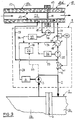
- a pipeline 1 for petroleum which consists of sections 1a, 1b, 1c and 1d, which are separated axially but by Pump lines 2 are connected to each other, in each of which one Feed pump 3, which is operated by an internal combustion engine 4 (e.g. a gas turbine) is driven.
- the section 1a is only very short; the feed point 5 is directly in front of it.
- the sections 1b, 1c and 1d are each 50 to 100 km long, the arrangement is set to the right practically any way. The diameter / length ratios are extremely exaggerated and not shown to scale.
- a pumping station 1, 8 is located in the area of separation points 6 and 9, to which the pump lines 2 and the internal combustion engines 4 belong. In this respect, it is the classic structure of a Oil transportation plant.
- the pipeline 10 for the sulfur transport runs out Sub-sections 10a, 10b, 10c and 10d.
- the separation points 11 are arranged with the same division as the separation points 6.
- the pipeline 10 consists of inner tubes 12 for the transport of sulfur and concentric for this purpose arranged heating jackets 13, the entire length of insulating sleeves 14 are surrounded, of which only a short section is shown.
- the inner tubes 12 of the individual sections 10a to 10d are nearby their separation points 11 by a pump line 15 with one each Feed pump 16 connected to each other. From separation point to separation point the pressure drops from 80 bar to about 12 bar and is replaced by the Feed pumps 16 raised again to 80 bar.
- the sulfur temperature is 157 ° C; it sinks to the next separation point 11 to about 125 ° C. Raising the temperature happens in the following way:
- FIG. 2 shows petroleum-heated combustion chambers 25 and 26 and 3.
- a control valve 28 and a pressure sensor are in the return line 27 29 shown by which the pressure in the line part 27a before the Feed pump 3 by a controller 31 to a predetermined value is adjustable, which is just above the pressure of the petroleum immediately before Separation point 6 is.
- the petroleum or heating medium can the pressure side of the feed pump 3 via a line 30 a small Quantity of petroleum taken as fuel and the combustion chamber 25 are supplied, from which a fuel gas line 32 via the exhaust line 24 leads to the primary side of the heat exchanger 18, for example, missing thermal energy to create. If the exhaust gas heat of the internal combustion engine 4 not used, the combustion chamber 25 takes over the sole heating of the heat exchanger 18.
- the feed pump 16 has an internal combustion engine as the drive 33, the exhaust gases of which via an exhaust pipe 34 and the exhaust pipe 24 can also be supplied to the primary side of the heat exchanger 18. Also however, this is not absolutely necessary, but is energetically advantageous.
- the arrangement of oil pipeline and sulfur pipeline can be the same Route together underground and / or - with appropriate insulation - can also be laid above ground.
- the heat exchanger 18 can also directly be designed as a heater ("Heater”), so that no separate Combustion chamber must be connected upstream.
- FIG. 4 shows a route diagram in which the transport route is on the abscissa and above that the pressure and temperature fluctuations in the sulfur line according to the following embodiment of the invention on which ordinate is plotted.
- the total distance of 1,000 km was the same in 10 Route sections of 100 km each, between which there are each a so-called booster station for reheating the Sulfur from 125 ° C to 155 ° C and the required pressure increase found.
- the flow pressure at the beginning of each section was 80 bar and 12 bar at the end of the section.
- the necessary The pressure increase was 68 bar.
- the crude oil pressure increased in the same booster stations.
- Temperature and pressure profiles are in Idealized form shown in Figure 4, between a start terminal "TLA" over 10 booster stations B1, B2, Across, B9, B10 up to one Terminal "TLE” or a tank “TK", which is in the above intervals are arranged.
- a heating output of 1 x 10 -6 kJ / h was required for each booster station to heat the sulfur from 125 ° C to 155 ° C.
- the heating energy was introduced into the sulfur via crude oil, which was removed from the pipeline and heated in an oil-heated heat exchanger from 135 ° to 165 ° C and fed to a heating jacket that surrounded the sulfur line concentrically.
- the amount of crude oil required to reheat the oil as a heat transfer medium was approx. 150 t / h or 3,600 t / day.
- the amount of heat transfer medium corresponded to about 12% of the transported crude oil amount of 30,000 t / day and was taken from the oil pipeline at the beginning of the entire transport route, ie "borrowed", and at the end, i.e. at the terminal or in front of an oil tank, again the main amount of the Crude oil supplied.
- This amount of heat transfer medium for the jacket heating of the sulfur line was therefore only transported via a second or parallel transport route and relieved the energy requirement for the transport of the crude oil in the oil pipeline.
- the annular gap for the heat transfer medium formed between the sulfur line and the heating jacket was 50 mm, ie the outside diameter of the coaxial line for the sulfur transport was 300 mm.
- the energy requirement for the sulfur line was approx. Per booster station 6 MW, with about 1 MW on the pumps to increase the pressure and about 5 MW heating the heat transfer medium for the heating jacket.
- Booster stations are calculated for the transport of 1,000 tons Sulfur over a distance of 1,000 km a power requirement of approx. 60 MW.
Landscapes
- Engineering & Computer Science (AREA)
- General Engineering & Computer Science (AREA)
- Mechanical Engineering (AREA)
- Health & Medical Sciences (AREA)
- Public Health (AREA)
- Water Supply & Treatment (AREA)
- Production Of Liquid Hydrocarbon Mixture For Refining Petroleum (AREA)
Applications Claiming Priority (2)
| Application Number | Priority Date | Filing Date | Title |
|---|---|---|---|
| DE19719772 | 1997-05-10 | ||
| DE19719772A DE19719772C2 (de) | 1997-05-10 | 1997-05-10 | Verfahren zum Transport von geschmolzenem Schwefel und Transportanlage hierfür |
Publications (1)
| Publication Number | Publication Date |
|---|---|
| EP0877197A2 true EP0877197A2 (fr) | 1998-11-11 |
Family
ID=7829187
Family Applications (1)
| Application Number | Title | Priority Date | Filing Date |
|---|---|---|---|
| EP98106401A Withdrawn EP0877197A2 (fr) | 1997-05-10 | 1998-04-08 | Méthode pour le transport de soufre fondu et système de transport correspondant |
Country Status (5)
| Country | Link |
|---|---|
| US (1) | US6026839A (fr) |
| EP (1) | EP0877197A2 (fr) |
| CN (1) | CN1203335A (fr) |
| CA (1) | CA2236902A1 (fr) |
| DE (1) | DE19719772C2 (fr) |
Families Citing this family (11)
| Publication number | Priority date | Publication date | Assignee | Title |
|---|---|---|---|---|
| ITMI20061737A1 (it) * | 2006-09-12 | 2008-03-13 | Snam Progetti | Procedimento per il trasporto di zolfo a basso rischio e ad emissione zero da depositi di zolfo solido in blocchi di notevoli dimensioni |
| US20080265564A1 (en) * | 2007-04-24 | 2008-10-30 | Rod Thomas | Multi-chamber vacuum insulated pipe systems and methods |
| US20090014163A1 (en) * | 2007-04-24 | 2009-01-15 | Rod Thomas | Temperature Controlled Pipe Systems And Methods |
| US8925543B2 (en) * | 2009-01-13 | 2015-01-06 | Aerojet Rocketdyne Of De, Inc. | Catalyzed hot gas heating system for pipes |
| US10036373B2 (en) * | 2014-03-11 | 2018-07-31 | Ge-Hitachi Nuclear Energy Americas Llc | Thermal pumping via in situ pipes and apparatus including the same |
| US10060289B2 (en) * | 2014-07-29 | 2018-08-28 | United Technologies Corporation | Geared gas turbine engine with oil deaerator and air removal |
| CN113280261B (zh) * | 2016-09-09 | 2023-05-12 | 恩文特服务有限责任公司 | 自动再熔化控制系统 |
| CN108758349B (zh) * | 2018-07-30 | 2023-09-29 | 中国石油工程建设有限公司 | 中长距离液体硫磺管道停输和再启动安全泄放系统及方法 |
| WO2020034594A1 (fr) * | 2018-08-16 | 2020-02-20 | 北京航天动力研究所 | Système de dépressurisation monté sur patin |
| US12276588B2 (en) | 2022-12-19 | 2025-04-15 | GM Global Technology Operations LLC | Systems and methods for measuring effects of vibration on rheometric properties of a fluid |
| US12392455B2 (en) * | 2023-04-14 | 2025-08-19 | GM Global Technology Operations LLC | System for transporting non-Newtonian materials using acoustic softening over long distances |
Citations (1)
| Publication number | Priority date | Publication date | Assignee | Title |
|---|---|---|---|---|
| US4137938A (en) | 1976-03-02 | 1979-02-06 | Logan Robert E A | Method and apparatus for transmitting liquid suphur over long distances |
Family Cites Families (6)
| Publication number | Priority date | Publication date | Assignee | Title |
|---|---|---|---|---|
| US3269401A (en) * | 1966-08-30 | Transporting wax-bearing petroleum fluids in pipelines | ||
| US3678243A (en) * | 1969-12-27 | 1972-07-18 | Chisso Corp | Method for levelling the temperature of an electrically heated pipeline |
| US3670752A (en) * | 1971-02-26 | 1972-06-20 | Sullivan S Marsden Jr | Pipelining crude oils and tars containing dissolved natural gas at sub-freezing temperatures in order to avoid environmental damage |
| US3846279A (en) * | 1972-09-18 | 1974-11-05 | Marathon Oil Co | Method for making and slurrying wax beads |
| US3977427A (en) * | 1975-09-18 | 1976-08-31 | John Zink Company | Control of the viscosity of fuel oil for burners |
| US4778586A (en) * | 1985-08-30 | 1988-10-18 | Resource Technology Associates | Viscosity reduction processing at elevated pressure |
-
1997
- 1997-05-10 DE DE19719772A patent/DE19719772C2/de not_active Expired - Fee Related
-
1998
- 1998-04-08 EP EP98106401A patent/EP0877197A2/fr not_active Withdrawn
- 1998-05-07 CA CA002236902A patent/CA2236902A1/fr not_active Abandoned
- 1998-05-08 US US09/074,764 patent/US6026839A/en not_active Expired - Fee Related
- 1998-05-09 CN CN98102498A patent/CN1203335A/zh active Pending
Patent Citations (1)
| Publication number | Priority date | Publication date | Assignee | Title |
|---|---|---|---|---|
| US4137938A (en) | 1976-03-02 | 1979-02-06 | Logan Robert E A | Method and apparatus for transmitting liquid suphur over long distances |
Non-Patent Citations (1)
| Title |
|---|
| "pipe line industry", September 1984, article "engineering considerations for long distance sulfur line", pages: 39 - 41 |
Also Published As
| Publication number | Publication date |
|---|---|
| US6026839A (en) | 2000-02-22 |
| CA2236902A1 (fr) | 1998-11-10 |
| CN1203335A (zh) | 1998-12-30 |
| DE19719772A1 (de) | 1998-12-03 |
| DE19719772C2 (de) | 1999-03-25 |
Similar Documents
| Publication | Publication Date | Title |
|---|---|---|
| DE2743918C3 (de) | Offene Gasturbinenanlage, mit der ein Dampfkreislauf kombiniert ist | |
| DE19719772C2 (de) | Verfahren zum Transport von geschmolzenem Schwefel und Transportanlage hierfür | |
| DE2523672C3 (de) | Einrichtung zur Verdampfung von verflüssigtem Erdgas mit Hilfe einer Gasturbinenanlage mit geschlossenem Kreislauf | |
| EP0874188B1 (fr) | Procédé pour le traitement d'un gaz liquéfié cryogénique | |
| EP2324194B1 (fr) | Procédé d'extraction de bitumes et/ou de pétrole extra-lourd d'un gisement souterrain, installation associée et procédé d'exploitation de cette installation | |
| DE19926326A1 (de) | Verfahren und Anlage zum Erwärmen eines flüssigen Mediums | |
| DE2657036A1 (de) | Verbessertes system zur nutzbarmachung von abwaerme und verfahren zu dessen herstellung und einbau | |
| DE2163096A1 (de) | Verfahren und vorrichtung zur aufheizung eines gasstromes, der durch vergasung von kohle bzw. kohlenstaub gewonnen wird | |
| EP2362935A2 (fr) | Procede et dispositif de recuperation d'energie thermique, notamment pour la production de courant electrique | |
| DE3208467A1 (de) | Konvektionserhitzer zum erhitzen von fluida, wie z.b. eine aufschlaemmung oder dergleichen | |
| DE4115431C2 (fr) | ||
| DE2063231C3 (de) | Verfahren zum Ausgleichen der Temperatur einer elektrisch geheizten Rohrleitung und Rohrleitung mit Temperaturausgleich | |
| EP0256292A2 (fr) | Procédé pour le transport combiné de produits liquides par route, chemin de fer ou eau au-dessus de la température de solidification | |
| DE2621340B2 (de) | Abhitzedampferzeuger | |
| DE3532979C2 (fr) | ||
| DE1590143C3 (de) | ölgefülltes, gekühltes Hochspannungskabel | |
| WO2015124141A1 (fr) | Dispositif et procédé pour chauffer des pipelines pour le transport de fluides | |
| DE3500338C2 (fr) | ||
| DE102015002063A1 (de) | Verfahren zur Verpumpung und Beheizung von Fluiden in Pipelines | |
| DE3814176C2 (de) | Doppelwandige Rohrleitung aus einer Vielzahl endseitig miteinander verbundener Rohrlängen | |
| CH552179A (de) | Heizanlage zum gleichmaessigen beheizen einer bodenflaeche. | |
| DE29504127U1 (de) | System zum energiesparenden Transport von insbesondere geothermischen Wärmeträgermedien | |
| DE2003133A1 (de) | Vorrichtung zum Erwaermen von durch Rohrleitungen gefuehrtem Rohoel | |
| EP4134512B1 (fr) | Dispositif de compensation de volume | |
| CH666339A5 (de) | Brenner. |
Legal Events
| Date | Code | Title | Description |
|---|---|---|---|
| PUAI | Public reference made under article 153(3) epc to a published international application that has entered the european phase |
Free format text: ORIGINAL CODE: 0009012 |
|
| AK | Designated contracting states |
Kind code of ref document: A2 Designated state(s): AT BE CH CY DE DK ES FI FR GB GR IE IT LI LU MC NL PT SE |
|
| AX | Request for extension of the european patent |
Free format text: AL;LT;LV;MK;RO;SI |
|
| STAA | Information on the status of an ep patent application or granted ep patent |
Free format text: STATUS: THE APPLICATION IS DEEMED TO BE WITHDRAWN |
|
| 18D | Application deemed to be withdrawn |
Effective date: 20001101 |