EP0877203A1 - Système à combustion avec oxydants doubles - Google Patents
Système à combustion avec oxydants doubles Download PDFInfo
- Publication number
- EP0877203A1 EP0877203A1 EP98108258A EP98108258A EP0877203A1 EP 0877203 A1 EP0877203 A1 EP 0877203A1 EP 98108258 A EP98108258 A EP 98108258A EP 98108258 A EP98108258 A EP 98108258A EP 0877203 A1 EP0877203 A1 EP 0877203A1
- Authority
- EP
- European Patent Office
- Prior art keywords
- fuel
- oxygen
- combustion zone
- air
- combustion
- Prior art date
- Legal status (The legal status is an assumption and is not a legal conclusion. Google has not performed a legal analysis and makes no representation as to the accuracy of the status listed.)
- Granted
Links
Images
Classifications
-
- F—MECHANICAL ENGINEERING; LIGHTING; HEATING; WEAPONS; BLASTING
- F23—COMBUSTION APPARATUS; COMBUSTION PROCESSES
- F23D—BURNERS
- F23D14/00—Burners for combustion of a gas, e.g. of a gas stored under pressure as a liquid
- F23D14/20—Non-premix gas burners, i.e. in which gaseous fuel is mixed with combustion air on arrival at the combustion zone
- F23D14/22—Non-premix gas burners, i.e. in which gaseous fuel is mixed with combustion air on arrival at the combustion zone with separate air and gas feed ducts, e.g. with ducts running parallel or crossing each other
-
- F—MECHANICAL ENGINEERING; LIGHTING; HEATING; WEAPONS; BLASTING
- F23—COMBUSTION APPARATUS; COMBUSTION PROCESSES
- F23D—BURNERS
- F23D14/00—Burners for combustion of a gas, e.g. of a gas stored under pressure as a liquid
- F23D14/32—Burners for combustion of a gas, e.g. of a gas stored under pressure as a liquid using a mixture of gaseous fuel and pure oxygen or oxygen-enriched air
-
- F—MECHANICAL ENGINEERING; LIGHTING; HEATING; WEAPONS; BLASTING
- F23—COMBUSTION APPARATUS; COMBUSTION PROCESSES
- F23D—BURNERS
- F23D2900/00—Special features of, or arrangements for burners using fluid fuels or solid fuels suspended in a carrier gas
- F23D2900/00006—Liquid fuel burners using pure oxygen or oxygen-enriched air as oxidant
Definitions
- the present invention relates generally to oxy-fuel combustion and more particularly to oxy-fuel combustion which additionally provides air to the combustion reaction.
- a number of combustion processes for a furnace use a burner supplied with air as an oxidizer in combination with a fuel, such as natural gas, fuel oil, propane, waste oils, other hydrocarbons, and the like. Attempts have been made to improve the performance of such air combustion processes by enriching the combustion atmosphere with oxygen enriched air, or pure oxygen gas. Oxygen enrichment of the combustion air increases both the burner flame temperature and the thermal efficiency while the furnace flue gas volume decreases as the oxygen concentration in the air or oxidizing gas increases.
- a fuel such as natural gas, fuel oil, propane, waste oils, other hydrocarbons, and the like.
- NO x nitric oxide
- high levels of oxygen enrichment e.g., above 90% total oxygen content in the oxidizer, could result in the production of less NO x than using air for the same burner firing rate.
- high levels of oxygen enrichment are costly to implement.
- one approach used to enrich the oxygen content of the combustion process is to install an oxy-fuel burner in the center of the existing air-fuel burner.
- This has a disadvantage in that it results in a relatively complex construction. Further, in such a burner it is difficult to control the two fuel streams and, at the same time, to adjust both the air and the oxygen for matching the fuel streams.
- Another approach is to design an oxy-fuel burner which can utilize a high level of oxygen as an oxidant and yet still maintain a moderate flame temperature and low NO x emissions. This involves a new burner installation involving more work which can be difficult and costly.
- the present invention relates to a retrofit system for an existing air-fuel burner to provide a second oxidant source.
- the invention provides a simple design which permits retrofitting to an existing air combustion system which can moderate and control the flame temperature when using oxygen.
- a conventional burner having an inner conduit serving as a fuel passage and an outer conduit which defines with the inner conduit a passage for air flow, is modified to add a conduit between the inner and outer conduits. This provides an additional passage between the outer and added conduit for a source of oxygen, which is used to improve the combustion process.
- Each oxidant flow and the fuel flow can be individually controlled to adjust the burner combustion characteristics and particularly to add a source of oxygen such that the production of NO x can be reduced.
- the invention is a simple retrofitting rather than a new installation, and results in lower capital costs and minimum furnace downtime during the installation.
- One aspect of the invention is:
- Another aspect of the invention is:
- a combustion method employing dual oxidants comprising:
- Yet another aspect of the invention is:
- a combustion method employing dual oxidants comprising:
- oxygen means a gaseous fluid having an oxygen concentration of at least 30 mole percent. It may have an oxygen concentration exceeding 85 mole percent or may be commercially pure oxygen having an oxygen concentration of 99.5 mole percent or more.
- a further object is to provide a retrofit for an existing air-fuel burner to convert it to a dual oxidant burner.
- Another object is to provide a dual oxidant burner formed by adding to a conventional air-fuel burner an arrangement for supplying oxygen.
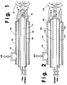
- Fig. 1 shows the parts of a conventional air-fuel burner which includes an outer conduit 12 and an inner conduit 14.
- the inner conduit 14 communicates with and receives fuel from a source (not shown), and has an end nozzle 16 of any suitable type through which the fuel is ejected under pressure into a furnace or combustion zone.
- the fuel can be of any suitable type, for example, natural gas, other hydrogen-carbon fuel gases, coke oven gas, oil, etc.
- an oxidant such as air is supplied in the annular passage between the inner surface of the outer tubular conduit 12 and the outer surface of the inner tubular conduit 14.
- a middle conduit, or pipe, 20 is fitted around the inner fuel conduit 14 in the space between the inner and outer conduits.
- the fuel exits from the openings of the nozzle 16.
- the fuel is surrounded by oxygen flowing through the inner annular passage 26 which communicates with a source of oxygen (not shown).
- the air which flows through the outer annular passage 24 is partially mixed with the fuel at the burner front. Passage 24 by means of passage 13 communicates with a source of air (not shown).
- control devices such as the valves shown, either manual or automatic, to control the flow in each of the fuel conduit 14 and the annular passages 24 and 26.
- the air/oxygen/fuel flow can be adjusted individually since each is from a separate source and each has its own flow passage.
- the end of the fuel conduit nozzle 16 is illustratively shown as extending beyond the outlet end of the inner annular passage 26. But this is not critical and the two ends can be flush.
- the end of the middle conduit 20 is shown extending beyond the end of the outer conduit 12, but this arrangement also is not critical.
- Fuel flowing through the inner conduit 14 is at a predetermined velocity, while the oxygen flowing through the inner annular passage 26 and air through the outer annular passage 24 can be at different, but lower, velocities. This has the advantage in that oxygen can be provided at a reduced pressure, which can be a cost saving due to the lower compressing power required.
- the velocity of the fuel from the inner conduit 14 can be varied over a wide range. Low NO x generation and moderate flame temperature can be achieved by having the fuel velocity equal to or greater than 400 ft/sec.
- Furnace gases 18, e.g. combustion reaction products, nitrogen, etc., are aspirated into the fuel gas stream rather than the streams of the two oxidants prior to combustion.
- a minimum amount of air (for the purpose of cooling the outer conduit 12) and a maximum amount of oxygen for a given fuel input are employed resulting in high thermal efficiency, good heat transfer and high total heat input to the furnace.
- the furnace does not require the high heat input and/or when the oxygen supply is limited, the oxygen input can be cut back substantially, and the dual oxidant burner will be functioning in approximation to an air burner. This provides a wide latitude of flexibility for furnace operation and control.
- Ranges of conditions and process variations can affect the performance of the dual oxidant burner of the invention. These include the relative amount of oxygen and air and the ratio of fuel velocity to oxygen velocity. For a given fuel input, the total amount of oxidants to be provided should be so as to provide at least 5% more oxygen molecules than stoichiometrically required for complete combustion of the fuel. Relative amounts of oxygen from passage 26 to the amount of oxygen molecules in the air from passage 24 air can be expressed as follows: (A) (B) (C) (D) (E) (F) (G) (H) (I) O 2 90% 80% 70% 60% 50% 40% 30% 20% 10% air 10% 20% 30% 40% 50% 60% 70% 80% 90%
- Condition (A) represents an oxy-fuel operation with a small amount of cooling air passing through the air passage 24.
- the minimum amount of cooling air depends on burner size and furnace conditions such as temperature and pressure.
- the 90%-10% split shown in condition (A) is for illustration purposes.
- condition (I) approximates an air burner operation.
- any of the above conditions ((A) to (I)) are applicable for the dual oxidant burner of the invention.
- the preferred mode of operation depends on the process requirement, production demands, furnace conditions, local emissions regulations and/or oxygen availability. From the combustion efficiency and/or heat transfer points of view, however, it is preferable to operate the burner in a manner wherein at least 80 percent of the oxygen molecules necessary to completely combust the fuel are provided by the oxygen passed into the furnace.
- the velocities of the oxidants are not the critical parameters.
- the velocity of fuel becomes a dominant factor.
- the fuel velocity should be at least 200 ft/sec, preferably at least 300 ft/sec most preferably at least 400 ft/sec.
- the invention has advantages in that it makes it easy to convert an existing air-fuel burner to oxy-fuel combustion. Further, the economics of using oxygen can be effectively controlled based on the processing requirements and economic conditions, such as the pricing of oxygen and fuel.
- Fig. 2 shows an air-fuel burner formed by an outer conduit 112 with an interior conduit 114 through which the fuel is supplied.
- an oxygen lance 116 is mounted in the interior of the fuel conduit 114. The nozzle end of the lance extends beyond the conduits 112, 114 forming the air burner.
- oxygen is injected through the nozzle 120 of the lance into the furnace or combustion zone and it mixes with (i) the fuel from the annular fuel passage 126 (formed between the inner surface of conduit 114 and the outer surface of lance 116) that surrounds the lance and (ii) the air from the annular passage 124 (formed between the outer surface of conduit 114 and the inner surface of conduit 116) that surrounds the fuel passage 126.
- the oxygen lance illustrated in Fig. 2 has two features, a high velocity oxygen jet from lance 116 and a low velocity air stream from passage 124.
- the high velocity oxygen jet from lance 116 enhances the aspiration of the surrounding combustion products 118, i.e. furnace gases, prior to mixing and combusting with the fuel provided by the existing air burner.
- the low velocity air stream provides flame stabilization.
- the amount of air provided by the existing air burner can be adjusted depending on the process requirements and production rate needed.
- the total amount of air and oxygen is controlled to be about 3 to 5 percent in excess of the stoichiometric amount needed to completely combust the fuel.
- the preferred mode of operation is to provide a minimum amount of air for cooling purposes and a maximum amount of oxygen through the lance for combustion. Under these conditions, higher thermal efficiency, improved heat transfer, maximum furnace gas recirculation/aspiration, and lower NO x emissions can be achieved.
- the burner illustrated in Fig. 2 can be considered as providing a kind of staged combustion.
- the old air-fuel burner is operated under a substoichiometric condition creating a fuel-rich zone immediately in front of the burner.
- the unburned fuel and the combustion products resulting from the combustion of the air and fuel will then be aspirated into the oxygen jets which already have been diluted with furnace gases. Complete combustion occurs at a certain distance away from the burner front.
- This high velocity oxygen lance enhances overall furnace recirculation, lowers peak flame temperature and avoids hot spots and furnace refractory damage. It will provide a desirable temperature distribution and result in low NO x emissions.
- the velocity of the oxygen injected through the nozzle 120 should be at least 300 ft/sec, and preferably is more than 500 ft/sec.
- dross formation can be controlled even at a higher production rate. It could be reduced on a basis of pound of dross formed per pound of product. This is an important economic factor in the aluminum industry.
- the lance illustrated in Fig. 2 may also provide a low velocity oxygen stream which acts as a flame stabilizer or flame holder. This is especially important when the burner is operated as an oxy-fuel burner with a minimum amount of air input and when the furnace is started up below the self-ignition temperature.
Landscapes
- Engineering & Computer Science (AREA)
- Chemical & Material Sciences (AREA)
- Combustion & Propulsion (AREA)
- Mechanical Engineering (AREA)
- General Engineering & Computer Science (AREA)
Applications Claiming Priority (2)
| Application Number | Priority Date | Filing Date | Title |
|---|---|---|---|
| US08/848,412 US5904475A (en) | 1997-05-08 | 1997-05-08 | Dual oxidant combustion system |
| US848412 | 1997-05-08 |
Publications (2)
| Publication Number | Publication Date |
|---|---|
| EP0877203A1 true EP0877203A1 (fr) | 1998-11-11 |
| EP0877203B1 EP0877203B1 (fr) | 2003-11-19 |
Family
ID=25303183
Family Applications (1)
| Application Number | Title | Priority Date | Filing Date |
|---|---|---|---|
| EP98108258A Expired - Lifetime EP0877203B1 (fr) | 1997-05-08 | 1998-05-06 | Procédé de combustion avec oxydants doubles |
Country Status (5)
| Country | Link |
|---|---|
| US (1) | US5904475A (fr) |
| EP (1) | EP0877203B1 (fr) |
| BR (1) | BR9801589A (fr) |
| DE (1) | DE69819811T2 (fr) |
| ES (1) | ES2206786T3 (fr) |
Cited By (5)
| Publication number | Priority date | Publication date | Assignee | Title |
|---|---|---|---|---|
| EP1078892A3 (fr) * | 1999-08-26 | 2003-02-05 | The Boc Group, Inc. | Procédé et four de fusion de verre avec brûleurs d'oxygène-combustible |
| FR2854943A1 (fr) * | 2003-05-13 | 2004-11-19 | Air Liquide | Procede de controle de bruleurs assurant le chauffage de canaux d'ecoulement de verre liquide |
| FR2863692A1 (fr) * | 2003-12-16 | 2005-06-17 | Air Liquide | Procede de combustion etagee avec injection optimisee de l'oxydant primaire |
| EP2405197A1 (fr) * | 2010-07-05 | 2012-01-11 | L'air Liquide, Societe Anonyme Pour L'etude Et L'exploitation Des Procedes Georges Claude | Procédé de combustion à maintenance réduire approprié à l'utilisation dans un avant-creuset de four à verre |
| EP2570725A3 (fr) * | 2011-09-19 | 2015-03-18 | Korea Hydro & Nuclear Power Co., Ltd. | Dispositif d'injection d'oxygène dans un four de vitrification |
Families Citing this family (33)
| Publication number | Priority date | Publication date | Assignee | Title |
|---|---|---|---|---|
| US6206686B1 (en) * | 1998-05-01 | 2001-03-27 | North American Manufacturing Company | Integral low NOx injection burner |
| FR2783595B1 (fr) * | 1998-09-22 | 2000-10-20 | Air Liquide | Procede de chauffage d'un four |
| FR2788110B1 (fr) * | 1998-12-30 | 2001-02-16 | Air Liquide | Procede de combustion et ses utilisations pour l'elaboration de verre et de metal |
| CA2323032A1 (fr) * | 1999-10-18 | 2001-04-18 | Air Products And Chemicals, Inc. | Methode et appareil de securite pour la combustion a l'oxygaz a l'aide de la combustion d'un melange air-combustible |
| US6250915B1 (en) * | 2000-03-29 | 2001-06-26 | The Boc Group, Inc. | Burner and combustion method for heating surfaces susceptible to oxidation or reduction |
| US6699031B2 (en) | 2001-01-11 | 2004-03-02 | Praxair Technology, Inc. | NOx reduction in combustion with concentrated coal streams and oxygen injection |
| US6699030B2 (en) | 2001-01-11 | 2004-03-02 | Praxair Technology, Inc. | Combustion in a multiburner furnace with selective flow of oxygen |
| US6699029B2 (en) | 2001-01-11 | 2004-03-02 | Praxair Technology, Inc. | Oxygen enhanced switching to combustion of lower rank fuels |
| US6702569B2 (en) | 2001-01-11 | 2004-03-09 | Praxair Technology, Inc. | Enhancing SNCR-aided combustion with oxygen addition |
| US20020127505A1 (en) | 2001-01-11 | 2002-09-12 | Hisashi Kobayashi | Oxygen enhanced low nox combustion |
| US6436337B1 (en) * | 2001-04-27 | 2002-08-20 | Jupiter Oxygen Corporation | Oxy-fuel combustion system and uses therefor |
| US6752620B2 (en) * | 2002-01-31 | 2004-06-22 | Air Products And Chemicals, Inc. | Large scale vortex devices for improved burner operation |
| ES2566798T3 (es) * | 2002-05-15 | 2016-04-15 | Praxair Technology, Inc. | Combustión con bajas emisiones de NOx |
| AU2003269127A1 (en) | 2002-05-15 | 2003-12-02 | Praxair Technology, Inc. | Combustion with reduced carbon in the ash |
| US7516620B2 (en) * | 2005-03-01 | 2009-04-14 | Jupiter Oxygen Corporation | Module-based oxy-fuel boiler |
| US8062027B2 (en) * | 2005-08-11 | 2011-11-22 | Elster Gmbh | Industrial burner and method for operating an industrial burner |
| US20070231761A1 (en) * | 2006-04-03 | 2007-10-04 | Lee Rosen | Integration of oxy-fuel and air-fuel combustion |
| US7717701B2 (en) * | 2006-10-24 | 2010-05-18 | Air Products And Chemicals, Inc. | Pulverized solid fuel burner |
| US7549858B2 (en) * | 2006-12-04 | 2009-06-23 | Praxair Technology, Inc. | Combustion with variable oxidant low NOx burner |
| DE102007025051B4 (de) * | 2007-05-29 | 2011-06-01 | Hitachi Power Europe Gmbh | Hüttengasbrenner |
| US7775791B2 (en) * | 2008-02-25 | 2010-08-17 | General Electric Company | Method and apparatus for staged combustion of air and fuel |
| DE102008058420A1 (de) * | 2008-11-21 | 2010-05-27 | Air Liquide Deutschland Gmbh | Verfahren und Vorrichtung zum Anwärmen eines Bauteils mit einem atmosphärischen Anwärmbrenner |
| RU2492389C2 (ru) * | 2009-01-16 | 2013-09-10 | Эр Продактс Энд Кемикалз, Инк. | Многорежимное устройство для осуществления горения и способ использования этого устройства |
| FR2941286B1 (fr) * | 2009-01-16 | 2012-08-31 | Air Liquide | Bruleur pilote air-gaz pouvant fonctionner a l'oxygene. |
| US20100233639A1 (en) * | 2009-03-11 | 2010-09-16 | Richardson Andrew P | Burner for reducing wall wear in a melter |
| US8087928B2 (en) * | 2009-03-25 | 2012-01-03 | Horn Wallace E | Laminar flow jets |
| US9587823B2 (en) | 2009-03-25 | 2017-03-07 | Wallace Horn | Laminar flow jets |
| US20110000261A1 (en) * | 2009-07-02 | 2011-01-06 | American Air Liquide, Inc. | Low Maintenance Burner for Glass Forehearth |
| EP2317222A1 (fr) * | 2009-10-30 | 2011-05-04 | L'AIR LIQUIDE, Société Anonyme pour l'Etude et l'Exploitation des Procédés Georges Claude | Procédé de combustion de combustible solide à particules avec un brûleur |
| WO2015007252A1 (fr) * | 2013-07-15 | 2015-01-22 | Flammatec, Spol. S R.O. | Procédé de combustion de gaz dans des fours industriels et brûleur pour réaliser ce procédé |
| US10344971B2 (en) * | 2016-06-13 | 2019-07-09 | Fives North American Combustion, Inc. | Low NOx combustion |
| JP6551375B2 (ja) * | 2016-12-07 | 2019-07-31 | トヨタ自動車株式会社 | 水素ガスバーナ構造およびこれを備えた水素ガスバーナ装置 |
| US12429215B2 (en) * | 2020-07-01 | 2025-09-30 | Messer Industries Usa, Inc. | Burner with a moveable air flow diverter |
Citations (5)
| Publication number | Priority date | Publication date | Assignee | Title |
|---|---|---|---|---|
| US4541796A (en) * | 1980-04-10 | 1985-09-17 | Union Carbide Corporation | Oxygen aspirator burner for firing a furnace |
| EP0340424A2 (fr) * | 1988-05-05 | 1989-11-08 | Praxair Technology, Inc. | Brûleur à jet d'oxygène et procédé de combustion |
| EP0529667A2 (fr) * | 1991-08-29 | 1993-03-03 | Praxair Technology, Inc. | Procédé d'injection de gaz à grande vitesse |
| EP0643262A1 (fr) * | 1993-09-09 | 1995-03-15 | L'air Liquide, Societe Anonyme Pour L'etude Et L'exploitation Des Procedes Georges Claude | Procédé de combustion |
| US5411395A (en) * | 1992-06-04 | 1995-05-02 | Praxair Technology, Inc. | Fuel jet burner |
Family Cites Families (9)
| Publication number | Priority date | Publication date | Assignee | Title |
|---|---|---|---|---|
| US4622007A (en) * | 1984-08-17 | 1986-11-11 | American Combustion, Inc. | Variable heat generating method and apparatus |
| CN1007920B (zh) * | 1985-07-15 | 1990-05-09 | 美国氧化公司 | 烃类流体燃料燃烧、控制方法及装置 |
| DE3735002A1 (de) * | 1987-10-16 | 1989-04-27 | Metallgesellschaft Ag | Verfahren zum entfernen von schwefelwasserstoff aus abgas |
| US4878829A (en) * | 1988-05-05 | 1989-11-07 | Union Carbide Corporation | Fuel jet burner and combustion method |
| US5257927A (en) * | 1991-11-01 | 1993-11-02 | Holman Boiler Works, Inc. | Low NOx burner |
| US5308239A (en) * | 1992-02-04 | 1994-05-03 | Air Products And Chemicals, Inc. | Method for reducing NOx production during air-fuel combustion processes |
| US5597298A (en) * | 1994-12-13 | 1997-01-28 | Praxair Technology, Inc. | Laminar flow burner |
| US5611683A (en) * | 1995-08-04 | 1997-03-18 | Air Products And Chemicals, Inc. | Method and apparatus for reducing NOX production during air-oxygen-fuel combustion |
| US5743723A (en) * | 1995-09-15 | 1998-04-28 | American Air Liquide, Inc. | Oxy-fuel burner having coaxial fuel and oxidant outlets |
-
1997
- 1997-05-08 US US08/848,412 patent/US5904475A/en not_active Expired - Lifetime
-
1998
- 1998-05-06 BR BR9801589A patent/BR9801589A/pt not_active IP Right Cessation
- 1998-05-06 DE DE69819811T patent/DE69819811T2/de not_active Expired - Fee Related
- 1998-05-06 EP EP98108258A patent/EP0877203B1/fr not_active Expired - Lifetime
- 1998-05-06 ES ES98108258T patent/ES2206786T3/es not_active Expired - Lifetime
Patent Citations (5)
| Publication number | Priority date | Publication date | Assignee | Title |
|---|---|---|---|---|
| US4541796A (en) * | 1980-04-10 | 1985-09-17 | Union Carbide Corporation | Oxygen aspirator burner for firing a furnace |
| EP0340424A2 (fr) * | 1988-05-05 | 1989-11-08 | Praxair Technology, Inc. | Brûleur à jet d'oxygène et procédé de combustion |
| EP0529667A2 (fr) * | 1991-08-29 | 1993-03-03 | Praxair Technology, Inc. | Procédé d'injection de gaz à grande vitesse |
| US5411395A (en) * | 1992-06-04 | 1995-05-02 | Praxair Technology, Inc. | Fuel jet burner |
| EP0643262A1 (fr) * | 1993-09-09 | 1995-03-15 | L'air Liquide, Societe Anonyme Pour L'etude Et L'exploitation Des Procedes Georges Claude | Procédé de combustion |
Cited By (10)
| Publication number | Priority date | Publication date | Assignee | Title |
|---|---|---|---|---|
| EP1078892A3 (fr) * | 1999-08-26 | 2003-02-05 | The Boc Group, Inc. | Procédé et four de fusion de verre avec brûleurs d'oxygène-combustible |
| FR2854943A1 (fr) * | 2003-05-13 | 2004-11-19 | Air Liquide | Procede de controle de bruleurs assurant le chauffage de canaux d'ecoulement de verre liquide |
| WO2004101453A1 (fr) * | 2003-05-13 | 2004-11-25 | L'Air Liquide, Société Anonyme à Directoire et Conseil de Surveillance pour l'Etude et l'Exploitation des Procédés Georges Claude | Procede de controle de bruleurs par injection d’un gaz additionnel et systeme de combustion y afferent |
| US9046264B2 (en) | 2003-05-13 | 2015-06-02 | L'Air Liquide Société Anonyme Pour L'Étude Et L'Exploitation Des Procedes Georges Claude | Method of controlling burners for heating liquid glass flow channels |
| FR2863692A1 (fr) * | 2003-12-16 | 2005-06-17 | Air Liquide | Procede de combustion etagee avec injection optimisee de l'oxydant primaire |
| WO2005059440A1 (fr) * | 2003-12-16 | 2005-06-30 | L'air Liquide Societe Anonyme A Directoire Et Conseil De Surveillance Pour L'etude Et L'exploitation Des Procedes Georges Claude | Procede de combustion etagee avec injection optimisee de l'oxydant primaire |
| CN100460757C (zh) * | 2003-12-16 | 2009-02-11 | 乔治洛德方法研究和开发液化空气有限公司 | 优化主氧化剂喷射的分级燃烧方法 |
| US8714969B2 (en) | 2003-12-16 | 2014-05-06 | L'air Liquide, Societe Anonyme Pour L'etude Et L'exploitation Des Procedes Georges Claude | Staged combustion method with optimized injection of primary oxidant |
| EP2405197A1 (fr) * | 2010-07-05 | 2012-01-11 | L'air Liquide, Societe Anonyme Pour L'etude Et L'exploitation Des Procedes Georges Claude | Procédé de combustion à maintenance réduire approprié à l'utilisation dans un avant-creuset de four à verre |
| EP2570725A3 (fr) * | 2011-09-19 | 2015-03-18 | Korea Hydro & Nuclear Power Co., Ltd. | Dispositif d'injection d'oxygène dans un four de vitrification |
Also Published As
| Publication number | Publication date |
|---|---|
| DE69819811D1 (de) | 2003-12-24 |
| ES2206786T3 (es) | 2004-05-16 |
| US5904475A (en) | 1999-05-18 |
| DE69819811T2 (de) | 2004-09-23 |
| BR9801589A (pt) | 1999-05-25 |
| EP0877203B1 (fr) | 2003-11-19 |
Similar Documents
| Publication | Publication Date | Title |
|---|---|---|
| US5904475A (en) | Dual oxidant combustion system | |
| US5871343A (en) | Method and apparatus for reducing NOx production during air-oxygen-fuel combustion | |
| EP0592081B1 (fr) | Brûleur aspiré à combustion étagée | |
| CA2175011C (fr) | Methode et appareil de reduction des emissions de nox dans un bruleur a gaz | |
| RU2288405C2 (ru) | Способ сжигания, включающий раздельное инжектирование топлива и окислителя, а также устройство для сжигания, предназначенное для осуществления данного способа | |
| EP0038257B2 (fr) | Brûleur aspirateur à oxygène et procédé pour chauffer un foyer avec un gaz oxydant enrichi d'oxygène | |
| US5195884A (en) | Low NOx formation burner apparatus and methods | |
| EP0543478B1 (fr) | Brûleur à combustion étagée | |
| EP4086512B1 (fr) | Brûleur pour combustion de combustible et procédé de combustion associé | |
| US20090061366A1 (en) | Integration of oxy-fuel and air-fuel combustion | |
| US5439373A (en) | Luminous combustion system | |
| PL173097B1 (pl) | Sposób spalania paliwa oraz urządzenie do przeprowadzania spalania paliwa | |
| EP1203188B1 (fr) | Bruleur industriel de carburant ameliore | |
| EP0076036B1 (fr) | Procédé et dispositif pour brûler du combustible en étapes | |
| US10684010B2 (en) | Burner assembly and method for combustion of gaseous or liquid fuel |
Legal Events
| Date | Code | Title | Description |
|---|---|---|---|
| PUAI | Public reference made under article 153(3) epc to a published international application that has entered the european phase |
Free format text: ORIGINAL CODE: 0009012 |
|
| AK | Designated contracting states |
Kind code of ref document: A1 Designated state(s): DE ES FR IT |
|
| AX | Request for extension of the european patent |
Free format text: AL;LT;LV;MK;RO;SI |
|
| 17P | Request for examination filed |
Effective date: 19981117 |
|
| AKX | Designation fees paid |
Free format text: DE ES FR IT |
|
| 17Q | First examination report despatched |
Effective date: 20010308 |
|
| RTI1 | Title (correction) |
Free format text: DUAL OXIDANT COMBUSTION METHOD |
|
| GRAH | Despatch of communication of intention to grant a patent |
Free format text: ORIGINAL CODE: EPIDOS IGRA |
|
| GRAS | Grant fee paid |
Free format text: ORIGINAL CODE: EPIDOSNIGR3 |
|
| GRAA | (expected) grant |
Free format text: ORIGINAL CODE: 0009210 |
|
| AK | Designated contracting states |
Kind code of ref document: B1 Designated state(s): DE ES FR IT |
|
| REF | Corresponds to: |
Ref document number: 69819811 Country of ref document: DE Date of ref document: 20031224 Kind code of ref document: P |
|
| REG | Reference to a national code |
Ref country code: ES Ref legal event code: FG2A Ref document number: 2206786 Country of ref document: ES Kind code of ref document: T3 |
|
| PGFP | Annual fee paid to national office [announced via postgrant information from national office to epo] |
Ref country code: DE Payment date: 20040630 Year of fee payment: 7 |
|
| ET | Fr: translation filed | ||
| PLBE | No opposition filed within time limit |
Free format text: ORIGINAL CODE: 0009261 |
|
| STAA | Information on the status of an ep patent application or granted ep patent |
Free format text: STATUS: NO OPPOSITION FILED WITHIN TIME LIMIT |
|
| 26N | No opposition filed |
Effective date: 20040820 |
|
| PG25 | Lapsed in a contracting state [announced via postgrant information from national office to epo] |
Ref country code: DE Free format text: LAPSE BECAUSE OF NON-PAYMENT OF DUE FEES Effective date: 20051201 |
|
| REG | Reference to a national code |
Ref country code: FR Ref legal event code: PLFP Year of fee payment: 19 |
|
| REG | Reference to a national code |
Ref country code: FR Ref legal event code: PLFP Year of fee payment: 20 |
|
| PGFP | Annual fee paid to national office [announced via postgrant information from national office to epo] |
Ref country code: FR Payment date: 20170525 Year of fee payment: 20 |
|
| PGFP | Annual fee paid to national office [announced via postgrant information from national office to epo] |
Ref country code: IT Payment date: 20170524 Year of fee payment: 20 Ref country code: ES Payment date: 20170601 Year of fee payment: 20 |
|
| REG | Reference to a national code |
Ref country code: ES Ref legal event code: FD2A Effective date: 20201001 |
|
| PG25 | Lapsed in a contracting state [announced via postgrant information from national office to epo] |
Ref country code: ES Free format text: LAPSE BECAUSE OF EXPIRATION OF PROTECTION Effective date: 20180507 |