EP0877232B1 - Compensation d'offset d'un capteur - Google Patents
Compensation d'offset d'un capteur Download PDFInfo
- Publication number
- EP0877232B1 EP0877232B1 EP98303053A EP98303053A EP0877232B1 EP 0877232 B1 EP0877232 B1 EP 0877232B1 EP 98303053 A EP98303053 A EP 98303053A EP 98303053 A EP98303053 A EP 98303053A EP 0877232 B1 EP0877232 B1 EP 0877232B1
- Authority
- EP
- European Patent Office
- Prior art keywords
- transducer
- signal
- output
- offset
- current
- Prior art date
- Legal status (The legal status is an assumption and is not a legal conclusion. Google has not performed a legal analysis and makes no representation as to the accuracy of the status listed.)
- Expired - Lifetime
Links
Images


Classifications
-
- H—ELECTRICITY
- H02—GENERATION; CONVERSION OR DISTRIBUTION OF ELECTRIC POWER
- H02P—CONTROL OR REGULATION OF ELECTRIC MOTORS, ELECTRIC GENERATORS OR DYNAMO-ELECTRIC CONVERTERS; CONTROLLING TRANSFORMERS, REACTORS OR CHOKE COILS
- H02P25/00—Arrangements or methods for the control of AC motors characterised by the kind of AC motor or by structural details
- H02P25/02—Arrangements or methods for the control of AC motors characterised by the kind of AC motor or by structural details characterised by the kind of motor
- H02P25/08—Reluctance motors
- H02P25/092—Converters specially adapted for controlling reluctance motors
- H02P25/0925—Converters specially adapted for controlling reluctance motors wherein the converter comprises only one switch per phase
-
- G—PHYSICS
- G01—MEASURING; TESTING
- G01R—MEASURING ELECTRIC VARIABLES; MEASURING MAGNETIC VARIABLES
- G01R15/00—Details of measuring arrangements of the types provided for in groups G01R17/00 - G01R29/00, G01R33/00 - G01R33/26 or G01R35/00
- G01R15/14—Adaptations providing voltage or current isolation, e.g. for high-voltage or high-current networks
- G01R15/20—Adaptations providing voltage or current isolation, e.g. for high-voltage or high-current networks using galvano-magnetic devices, e.g. Hall-effect devices, i.e. measuring a magnetic field via the interaction between a current and a magnetic field, e.g. magneto resistive or Hall effect devices
- G01R15/202—Adaptations providing voltage or current isolation, e.g. for high-voltage or high-current networks using galvano-magnetic devices, e.g. Hall-effect devices, i.e. measuring a magnetic field via the interaction between a current and a magnetic field, e.g. magneto resistive or Hall effect devices using Hall-effect devices
-
- G—PHYSICS
- G01—MEASURING; TESTING
- G01R—MEASURING ELECTRIC VARIABLES; MEASURING MAGNETIC VARIABLES
- G01R35/00—Testing or calibrating of apparatus covered by the other groups of this subclass
- G01R35/005—Calibrating; Standards or reference devices, e.g. voltage or resistance standards, "golden" references
Definitions
- This invention relates to offset compensation of the output of a transducer.
- the invention is particularly, though not exclusively, applicable to offset compensation in current measurement in the control of a switched reluctance machine.
- the resistor must be connected directly in the circuit to be monitored. This alone makes resistance current monitoring impracticable in, for example, power circuits in which the current to be monitored is in a circuit at a high potential with respect to the circuit to which the monitored current signal is to be relayed. Thirdly, connecting the resistor in the monitored circuit may distort the operation of the circuit itself to an unacceptable degree.
- CT's are a form of transducer by which a measure of current in a conductor can be derived. They are electrically isolated from the conductor itself and they have found extensive use in the field of electrical power engineering as, for example, monitors in current regulation and protection systems.
- a known CT relies on the substantial balance of magnetomotive force (MMF) between primary and secondary windings that would exist in a CT using a high permeability core.
- MMF magnetomotive force
- burden a zero secondary circuit impedance
- the core flux is proportional to the integral of the secondary voltage.
- the amplitude of the core flux will therefore be inversely proportional to the frequency of the monitored current.
- the finite permeability of a real core requires MMF to drive the flux around the core. Assuming a linear response of the magnetic material of the core, this MMF will be directly proportional to the flux. As the core flux increases, a larger MMF will be needed to support it. Thus, with decreasing frequency the CT core absorbs an increasing proportion of the primary MMF. Therefore, the secondary MMF and the output current must fall.
- a low frequency CT means both a large core and a low secondary impedance to offer a flat frequency response over a specified working frequency range.
- known CT's cannot operate at dc (zero frequency) because of the non-zero secondary circuit resistance which is present in practice.
- a known current transducer based on the Hall effect uses a Hall-effect device arranged in an air gap in an otherwise toroidal core.
- the conductor carrying the current to be monitored is arranged to pass through the central aperture of the toroid.
- the Hall-effect device in the gap measures directly the flux resulting from the introduction of MMF in the core due to the current in the conductor.
- the device is relatively simply constructed, it has some disadvantages. Firstly, the response of the core material is not linear in practice. Secondly, the Hall-effect device also has a non-linear response and displays characteristics which introduce a static offset error into measurements. Furthermore, the small amplitude of the Hall voltage at the output of the device requires relatively large gain amplification which may render the monitoring circuit as a whole unacceptably prone to noise.
- the open-loop Hall-effect element tends to exhibit inconsistency in its output offset characteristics. That is, the output can be expressed as (k*I) + c, where c is a non-constant offset term.
- the value of c may vary significantly from transducer to transducer, and may also vary with time, temperature, supply voltage and other factors. This can be a significant deterrent to using what would otherwise be an attractive, low-cost solution.
- one manufacturer offers a range of current sensors based on their Hall-effect device, but the output offset voltage of their low-cost unit varies by ⁇ 10% initially, is proportional to supply voltage and exhibits a temperature coefficient of ⁇ 0.05% per Kelvin. The initial offset can be trimmed out, but the temperature and supply-dependent offset variations may be less easy to deal with.
- Such transducers of the "flux-nulling" Hall-effect type have been popular in the electric machine control field (for example on switched reluctance motors and generators) because of their dc response, wide bandwidth and small size.
- An example of the flux-nulling sensor is one manufactured by LEM s.a. of Geneva, Switzerland. These sensors are non-invasive and electrically isolated from the monitored current. However, they are relatively expensive because they need an accurately zeroed Hall-effect element and fast responding amplifiers.
- JP02141673 employs a system for determining Hall current transformer offset which utilises two power supplies to provide phase current to a motor and requires two transducer circuits.
- the phase current is supplied to the motor by alternately chopping two switches, one for each of the power supplies. Subsequent processing of the signals from the transducer circuits and then combination of them allows measurement of the phase current which has the transducer offset filtered out.
- a transducer circuit comprising a transducer operable to produce an electrical transducer output signal indicative of the magnitude of a monitored parameter, sampling means for sampling the transducer output signal at a moment corresponding to a known value of the parameter, the sampling means providing an offset signal which is equivalent to the transducer signal at the said moment, and a differencer arranged to receive a subsequent transducer output signal and the offset signal and to produce a compensated output which is the difference between the subsequent transducer output and at least the offset signal.
- the invention requires knowledge of the moment at which the monitored magnitude of the parameter will be at a known value, or knowledge of the value of the parameter at a known moment.
- the compensation applied takes account of any deviation in the output from the transducer with respect to the known value of the parameter and adjusts the transducer output automatically.
- the invention is particularly useful in situations in which the known value of the parameter is zero (typically zero current for zero output from an ideal Hall-effect element).
- adjustment for non-zero outputs from the transducer corresponding to the known value can be effected by including an adder in the circuit which is arranged in relation to the differencer such that a reference signal corresponding to the said known value of the parameter is added to the compensated output.
- the sampling means comprise a sample and hold circuit.
- This is desirably a combination of a switch gating the output of the transducer to a storage capacitor.
- the output of the transducer is supplied to the capacitor to store the transducer output signal at the said moment.
- the sampling means may include an analogue to digital converter (ADC) which is operable, in response to an actuating signal at the said moment, to derive the offset signal in the form of a digital word from the transducer signal.
- ADC analogue to digital converter
- the digital word is stored in a digital word store which supplies the digital word to the differencer.
- the circuit may further comprise a second differencer which may be a digital subtractor to which the reference signal is applied in digital form.
- the output of the differencer may be supplied to a digital-to-analogue converter (DAC), providing an analogue signal indicative of the difference between the offset digital word and the reference digital word. This may then be applied to the differencer together with the transducer output signal.
- DAC digital-to-analogue converter
- the differencer is a digital differencer which is operable to derive a digital form of compensated output.
- the invention extends to a method of compensating for offset in the output of an electrical transducer producing an electrical transducer signal in response to a monitored parameter, the method comprising: sampling the transducer output signal at a moment corresponding to a known value of the parameter; and taking the difference between a subsequent transducer output signal and the sample transducer output signal to produce a compensated output.
- the method may include adding a reference signal to the compensated output that corresponds to the correct transducer output for the said known value of the parameter at the said moment. This is particularly useful in those cases where the known value of the parameter is non-zero.
- the invention also extends, in a particular form, to a switched reluctance drive system comprising a switched reluctance machine having a rotor and a stator and at least one stator winding, switch means connected with the stator winding and being actuatable to control the energy in the winding, and a controller operably connected to actuate the switch means, the controller comprising timing means from which timing signals are derived for actuating the switch means, and a transducer circuit arranged to monitor the current in the winding which current has a known value during a recurring interval, the transducer circuit comprising a current transducer responsive to current in the winding to produce an electrical transducer output signal indicative of the monitored current, sampling means for sampling the transducer signal at a moment coincident with the known current, the sampling means providing an offset signal which is equivalent to the transducer signal at the said moment, a differencer arranged to receive a subsequent transducer output signal and the offset signal and to produce a compensated output which is the difference
- a cyclically recurring interval of zero-current can be used as the known current.
- This zero-current interval is taken in the invention because it allows regular offset compensation without recourse to a reference signal input by sampling the output from the current transducer during the zero-current interval.
- the transducer includes a Hall-effect element.
- a simple circuit can be used including the Hall-effect element, or any other transducer connected in an open-loop arrangement.
- a current sensor is shown in Figure 1 comprising a Hall-effect element 10 which is arranged in the air gap of a ferromagnetic toroidal ring 12.
- the ring 12 embraces a conductor 14 carrying the current I which is the parameter to be monitored in this embodiment.
- the output of the Hall-effect element 10 is described above as (k*I) + c, where c is a non-constant offset term.
- This output is connected to the non-inverting input of a differencing circuit 16.
- the output of the Hall-effect element is also connected with a sample and hold circuit 18 comprising a first buffer amplifier 20, a sampling switch 22 and a second buffer amplifier 24 all connected in series and forming a parallel connection of the Hall-effect element output to the inverting input of the differencing circuit 16.
- a holding capacitor 26 is connected between the sampling switch 22 and the second buffer amplifier 24 to ground.
- a third input I r to a non-inverting input of the differencing circuit 16 is a reference signal corresponding to the calibrated output of the transducer indicative of the known current at a predetermined moment.
- Figure 1 represents an analogue implementation of the invention.
- the sample and hold circuit 18 is effectively updated with the output from the Hall-effect element.
- the output of the Hall-effect element for zero current at a known moment at which the sample is taken will comprise only the offset term c
- the difference between the updated offset signal stored in the sample and hold circuit 18 and any subsequent output from the transducer is automatically compensated for drift or offset present in the output.
- the calibrated output of the transducer as it should be without drift is applied as the reference signal I r to be added to the result of the difference between the subsequent transducer output and the stored offset signal.
- the scheme uses prior knowledge of the current to be measured at a particular moment to derive the offset signal from the actual output of the transducer. This allows any offset to be eliminated.
- FIG 2(a) shows a typical phase winding current waveform (I) in a switched reluctance motor, where the invention can be applied to advantage.
- the phase current I at the end of each electrical cycle is known to be zero when the motor is run in a discontinuous phase current mode of operation.
- the switch 22 is momentarily closed by means of an actuation signal pulse 28, thus storing the offset as a voltage (corresponding to zero current) in the capacitor 26.
- the actuation pulse 28 is shown in Figure 2(b).
- the time T o is not necessarily known to the central system but T 1 (the instant at which the phase winding is re-energised) is known, it may be convenient to employ an actuation pulse 28', as shown in Figure 2(c), beginning at T 1 and ending a short time thereafter at T 2 . Since in a typical switched reluctance machine the period of the phase current cycle (i.e. T 3 -T o ) may be comparatively short (e.g. several milliseconds), the error introduced by opening the sample-and-hold switch 22 after the interval of zero current (i.e. T o to T 1 ) will be small.
- the offset voltage is subtracted from the subsequent sensor output, so giving a more accurate current measurement compensated for offset. Providing the offset is sampled often enough, offset drift due to temperature and supply voltage variations will be largely cancelled. Only the variation over a sample interval will remain. In the case of a switched reluctance machine, the current at the moment in question is known to be zero. Therefore, this embodiment of the invention does not require a bias input to the comparator indicative of the reference current I r at the predetermined moment.
- FIG 3 a partly digital implementation of the invention is shown.
- the output from the Hall-effect element 10 is applied to a digital sample and hold circuit 18' comprising an analogue-to-digital converter (ADC) 30, the digital offset word being stored in an offset store 32.
- a digital version of the current reference word I r representing the known current at the predetermined moment is subtracted from the offset word being stored in the store 32 in a digital subtractor.
- the difference between the offset word and the current reference word I r represented by the output of the subtractor 33 is applied to a digital-to-analogue convertor (DAC) 34 and the analogue output from the DAC 34 is applied to the inverting input to the analogue differencing circuit 16 where it is subtracted from the output of the Hall-effect element 10.
- DAC digital-to-analogue convertor
- the output of the differencing circuit 16 is the offset adjusted (compensated) signal from the Hall-effect element 10 indicative of the monitored current.
- the sample and hold circuit 18' is caused to take a sample of the output of the Hall-effect element by means of the pulse 28 at the zero current points. This also loads the uncompensated word in the offset store 32.
- the reference current I r is generated digitally, then the difference between the word in the offset store and I r is compared with the actual value in the analogue domain. This is likely to be necessary in some applications of switch-based electrical regulation where a software-based, fully digital, output may be too slow to implement the actual current control.
- the phase winding current is part of the information fed back by which the controller effects its algorithmic control regime. Because the current feedback signal is driven by the difference between the output of the Hall-effect element 10 and the output of the DAC 34, adding the offset to the negated reference signal is equivalent to subtracting it from the Hall-effect element output. This arrangement offers the advantage that the sample and hold circuit and the subtractor 33 can be implemented entirely in software.
- the invention provides a low-cost monitoring system offering reduced offset drift. It also eliminates the need for initial trimming of the offset parameter for individual transducers, amplifiers etc. It makes use of intervals where the waveform is known to have a particular value, and is therefore well-suited to use in a switched reluctance drive.
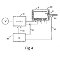
- FIG. 4 illustrates a switched reluctance drive in which the invention is implemented. It comprises a three-phase switched reluctance machine 36 which, for the sake of illustration, will be described in terms of a motor.
- the machine has phase windings A, B and C, a rotor R and stator S.
- the machine 36 is controlled by a microprocessor-based controller 38 which receives feedback signals from a rotor position transducer 40, as is well known in the art, and phase current information from the Hall-effect element 10 on lines 42 and 44, respectively.
- the controller 38 According to known control strategies, the controller 38 generates firing signals on lines 46 which control the actuation of conventional switch apparatus 48 applying voltage to the phase windings from an electrical source V.
- the reference timing derived by the controller 38 to actuate the switches is also used to determine the moments at which the current in one of the phase windings will be zero. It is at this calculated moment that the offset reading, in either analogue or digital form, is taken by sampling the output of the Hall-effect element 10. The zero current moments will recur frequently as the rotor of the motor rotates, so allowing the offset value or word to be updated before significant drift from the last compensation was made.
- this invention is applicable to any transducer that is subject to drift or other offset from a calibrated condition over time.
- the invention is particularly applicable to, for example, electrical machines in which a known value of the monitored parameter will recur regularly and, preferably, periodically according to a known cycle.
- it is equally applicable to other transducers measuring other parameters in which there is a need for output offset compensation.
- the principles of the present invention which have been disclosed by way of the above examples and discussion, can be implemented using various circuit types and arrangements and can be applied in different ways. Those skilled in the art will readily recognise that these and various other modifications and changes may be made to the present invention without strictly following the exemplary application illustrated and described herein and without departing from the true spirit and scope of the present invention which is set forth in the following claims.
Landscapes
- Engineering & Computer Science (AREA)
- Power Engineering (AREA)
- Measurement Of Current Or Voltage (AREA)
- Control Of Electric Motors In General (AREA)
- Control Of Motors That Do Not Use Commutators (AREA)
Claims (18)
- Circuit de capteur comprenant un capteur unique (10) pour produire un signal de sortie indicatif de la grandeur d'un paramètre surveillé (I), des moyens d'échantillonnage (18) pour échantillonner le signal de sortie du capteur à un moment correspondant à une valeur connue de la grandeur du paramètre, les moyens d'échantillonnage étant agencés de façon à stocker le signal de sortie échantillonné comme un signal de décalage, le circuit comprenant en outre un soustracteur (16) agencé de façon à recevoir au moins un signal de sortie de capteur suivant et le signal de décalage et à produire une sortie compensée qui est la différence entre le signal de sortie de capteur suivant et au moins le signal de décalage.
- Circuit suivant la revendication 1 dans lequel les moyens d'échantillonnage comprennent un circuit d'échantillonnage et de maintien, le circuit d'échantillonnage et de maintien pouvant être activé pour échantillonner le signal de sortie de capteur audit moment et pour maintenir la sortie échantillonnée comme signal de décalage.
- Circuit selon la revendication 1 ou 2 dans lequel le soustracteur est en outre agencé de façon à recevoir un signal de référence (Ir) correspondant à une sortie calibrée du capteur audit moment de telle façon que le signal de référence soit ajouté à la sortie compensée.
- Circuit selon l'une quelconque des revendications précédentes dans lequel les moyens d'échantillonnage comprennent un dispositif déclencheur et un condensateur de stockage, le dispositif déclencheur pouvant être activé audit moment pour permettre à la sortie du capteur d'être appliquée au condensateur de stockage et stockée dans celui-ci comme signal de décalage.
- Circuit selon la revendication 1 ou 2 dans lequel les moyens d'échantillonnage comprennent un convertisseur analogique-numérique ADC (30) et une mémoire de mots numériques (32) agencés de façon à recevoir la sortie de l'ADC, l'ADC pouvant être activé, en réponse à un signal d'activation, pour convertir la sortie du capteur audit moment en un mot numérique, le mot numérique étant mémorisable dans la mémoire de mots numériques comme signal de décalage.
- Circuit selon la revendication 5, comprenant en outre un deuxième soustracteur (33) agencé de façon à produire une sortie qui est la différence entre le signal de décalage et le signal de référence sous la forme d'un mot de référence, le circuit comprenant en plus un convertisseur numérique-analogique DAC (34) agencé de façon à convertir ledit mot de référence en un-signal analogique et à transmettre le signal analogique au soustracteur (16).
- Circuit selon l'une quelconque des revendications précédentes dans lequel le capteur est un capteur de courant, comprenant par exemple un élément à effet de Hall.
- Système d'entraínement de machine électrique comprenant une machine électrique, un dispositif de commande de la machine et un circuit de capteur selon l'une quelconque des revendications 1 à 7.
- Système selon la revendication 8 dans lequel le capteur est un capteur de courant agencé de façon à surveiller un courant dans la machine électrique.
- Système selon la revendication 8 ou 9 dans lequel la machine électrique est une machine à réluctance commutée pouvant être activée selon un cycle d'inductance de phase et le dispositif de commande peut être commandé de façon à activer les moyens d'échantillonnage pendant le cycle d'inductance de phase de la machine électrique.
- Système selon la revendication 10 dans lequel le capteur est agencé de façon à surveiller un courant afin de produire un signal indicatif du courant d'enroulement, ledit moment coïncidant avec un intervalle à courant substantiellement nul dans l'enroulement.
- Procédé pour compenser le décalage dans la sortie d'un capteur unique dans une machine électrique, le procédé comprenant les étapes suivantes:échantillonner le signal de sortie du capteur à un moment correspondant à une valeur connue de la grandeur du paramètre surveillé par le capteur;stocker le signal de sortie échantillonné comme signal de décalage; etprendre la différence entre au moins un signal de sortie de capteur suivant et le signal de décalage pour produire une sortie compensée qui est la différence entre le signal de sortie de capteur suivant et au moins le signal de décalage.
- Procédé selon la revendication 12, comprenant l'étape de déclenchement du signal de sortie de capteur audit moment et de stockage dudit signal de sortie de capteur dans un condensateur de stockage.
- Procédé selon la revendication 12, comprenant l'étape de soustraction d'un signal de référence correspondant à la sortie du capteur audit moment à partir du signal de décalage afin de produire une sortie sous la forme d'une deuxième différence entre la sortie des moyens d'échantillonnage et le signal de référence, et de prise de la différence entre le signal de sortie de capteur suivant et la deuxième différence.
- Procédé selon la revendication 12 ou la revendication 14, comprenant l'étape de conversion de la sortie du capteur audit moment en un mot numérique et de stockage du mot numérique dans une mémoire de mots numériques comme mot de décalage.
- Procédé selon la revendication 15, lorsqu'elle dépend de la revendication 14, dans lequel la sortie se trouve sous la forme d'un mot numérique produit en soustrayant le signal de référence sous la forme d'un mot de référence à partir du mot de décalage, et le mot numérique est converti en un signal analogique, la différence prise étant la différence entre le signal de sortie de capteur suivant et le signal analogique.
- Procédé selon l'une quelconque des revendications 12 à 16 dans lequel le paramètre est un courant dans une machine électrique.
- Procédé selon la revendication 17 dans lequel la machine est une machine à réluctance commutée et le courant surveillé fournit un signal indicatif du courant d'enroulement dans la machine, ledit moment coïncidant avec un intervalle à courant substantiellement nul dans l'enroulement.
Applications Claiming Priority (2)
| Application Number | Priority Date | Filing Date | Title |
|---|---|---|---|
| GB9709498 | 1997-05-09 | ||
| GBGB9709498.1A GB9709498D0 (en) | 1997-05-09 | 1997-05-09 | Transducer offset compensation |
Publications (3)
| Publication Number | Publication Date |
|---|---|
| EP0877232A2 EP0877232A2 (fr) | 1998-11-11 |
| EP0877232A3 EP0877232A3 (fr) | 1999-11-10 |
| EP0877232B1 true EP0877232B1 (fr) | 2004-10-27 |
Family
ID=10812101
Family Applications (1)
| Application Number | Title | Priority Date | Filing Date |
|---|---|---|---|
| EP98303053A Expired - Lifetime EP0877232B1 (fr) | 1997-05-09 | 1998-04-21 | Compensation d'offset d'un capteur |
Country Status (4)
| Country | Link |
|---|---|
| US (1) | US6400131B1 (fr) |
| EP (1) | EP0877232B1 (fr) |
| DE (1) | DE69827191T2 (fr) |
| GB (1) | GB9709498D0 (fr) |
Families Citing this family (17)
| Publication number | Priority date | Publication date | Assignee | Title |
|---|---|---|---|---|
| GB9920988D0 (en) * | 1999-09-07 | 1999-11-10 | Trw Lucas Varity Electric | Motor control |
| US7438073B2 (en) * | 2002-03-08 | 2008-10-21 | Kaerys S.A. | Air assistance apparatus for computing the airflow provided by only means of pressure sensors |
| US6817760B2 (en) * | 2002-11-22 | 2004-11-16 | Tektronix, Inc. | Method of monitoring current probe transformer temperature |
| JP2007506089A (ja) * | 2003-09-22 | 2007-03-15 | コニンクリユケ フィリップス エレクトロニクス エヌ.ブイ. | 電流センサのゼロポイントを決定する方法 |
| US7201244B2 (en) | 2003-10-03 | 2007-04-10 | Letourneau, Inc. | Vehicle for materials handling and other industrial uses |
| US7957831B2 (en) | 2008-04-04 | 2011-06-07 | Isaacs Robert E | System and device for designing and forming a surgical implant |
| US8549888B2 (en) | 2008-04-04 | 2013-10-08 | Nuvasive, Inc. | System and device for designing and forming a surgical implant |
| DE102011053065A1 (de) | 2010-09-03 | 2012-03-08 | Sma Solar Technology Ag | Verfahren zur Messung von Wechselströmen, die ein dreiphasiger Wechselrichter über ein Dreileitersystem in ein Wechselstromnetz einspeist |
| US8604777B2 (en) | 2011-07-13 | 2013-12-10 | Allegro Microsystems, Llc | Current sensor with calibration for a current divider configuration |
| FR2982674B1 (fr) | 2011-11-10 | 2015-01-16 | Renault Sas | Procede et systeme de mesure de courant electrique |
| US8653829B2 (en) * | 2011-11-30 | 2014-02-18 | Standard Microsystems Corporation | Method and system for high gain auto-zeroing arrangement for electronic circuits |
| CN103163369B (zh) * | 2011-12-19 | 2015-10-28 | 无锡华润矽科微电子有限公司 | 实现测量精度预校准功能的电能计量电路结构及其方法 |
| CN104833932B (zh) * | 2014-07-03 | 2017-12-08 | 北汽福田汽车股份有限公司 | 电流传感器的漂移量计算方法和计算装置 |
| DE102014113677B4 (de) * | 2014-09-22 | 2019-07-25 | Jungheinrich Ag | Flurförderzeug mit einer Strommesseinrichtung |
| DE102016225305B4 (de) | 2016-12-16 | 2019-07-11 | Fraunhofer-Gesellschaft zur Förderung der angewandten Forschung e.V. | Verfahren zur Offset-Kompensation eines Sensorsignals eines Hall-Sensors und Sensoranordnung |
| KR102699879B1 (ko) * | 2019-12-06 | 2024-08-29 | 삼성전기주식회사 | 홀 센서 출력단자 전압 감시 회로 및 렌즈 모듈 구동 제어기 지원 회로 |
| CN114915196A (zh) * | 2022-04-21 | 2022-08-16 | 北京行实科技有限公司 | Npc-i型三电平母线中点平衡系统、方法、电子设备及介质 |
Family Cites Families (17)
| Publication number | Priority date | Publication date | Assignee | Title |
|---|---|---|---|---|
| US3543169A (en) * | 1967-10-30 | 1970-11-24 | Bell Telephone Labor Inc | High speed clamping apparatus employing feedback from sample and hold circuit |
| GB1435696A (en) * | 1972-09-01 | 1976-05-12 | Kodak Ltd | Amplifier circuits |
| US4008398A (en) * | 1974-03-11 | 1977-02-15 | Schramm Benjamin B | Transducer signal conditioning circuit |
| US3925639A (en) * | 1974-03-25 | 1975-12-09 | Msi Data Corp | Method and apparatus for reading bar coded data wherein a light source is periodically energized |
| US4371837A (en) * | 1979-11-13 | 1983-02-01 | American Can Company | Temperature compensated input power and output offset circuits for a hall effect transducer |
| NL7909177A (nl) * | 1979-12-20 | 1981-07-16 | Philips Nv | Amplitudemodulatorschakeling voor het moduleren van een videosignaal op een draaggolfsignaal. |
| US4356446A (en) * | 1981-03-23 | 1982-10-26 | Transdata, Inc. | Time division multiplier transducer with selective phase shift |
| US4551754A (en) * | 1982-02-18 | 1985-11-05 | Rca Corporation | Compatible wide-screen color television system |
| US4520298A (en) * | 1984-04-03 | 1985-05-28 | Westinghouse Electric Corp. | Method and apparatus for sampling output AC currents in a voltage-fed inverter power supply |
| US4688097A (en) * | 1986-10-30 | 1987-08-18 | Jerrold Electronics Corp. | D.C.-coupled video clamping circuit |
| DE3832145A1 (de) * | 1988-09-22 | 1990-03-29 | Philips Patentverwaltung | Verfahren und schaltungsanordnung zur messung kleiner elektrischer signale |
| JPH02141673A (ja) * | 1988-11-22 | 1990-05-31 | Meidensha Corp | ホールctオフセット自動補正電流検出回路 |
| US5028876A (en) * | 1989-01-30 | 1991-07-02 | Dresser Industries, Inc. | Precision capacitive transducer circuits and methods |
| GB2228643B (en) * | 1989-02-28 | 1993-05-19 | Sony Corp | Video signal clamping |
| JPH04184267A (ja) * | 1990-11-20 | 1992-07-01 | Fuji Electric Co Ltd | ホール変流器のオフセット調整装置 |
| WO1996028837A1 (fr) * | 1995-03-10 | 1996-09-19 | Molecular Imaging Corporation | Systeme de controle hybride pour microscope a sonde d'exploration |
| GB2311423B (en) * | 1996-03-19 | 2000-05-10 | Switched Reluctance Drives Ltd | An electrical machine drive system including an optical position transducer circuit |
-
1997
- 1997-05-09 GB GBGB9709498.1A patent/GB9709498D0/en active Pending
-
1998
- 1998-04-21 DE DE69827191T patent/DE69827191T2/de not_active Expired - Lifetime
- 1998-04-21 EP EP98303053A patent/EP0877232B1/fr not_active Expired - Lifetime
- 1998-05-08 US US09/074,854 patent/US6400131B1/en not_active Expired - Lifetime
Also Published As
| Publication number | Publication date |
|---|---|
| US6400131B1 (en) | 2002-06-04 |
| DE69827191T2 (de) | 2006-02-02 |
| EP0877232A3 (fr) | 1999-11-10 |
| DE69827191D1 (de) | 2004-12-02 |
| GB9709498D0 (en) | 1997-07-02 |
| EP0877232A2 (fr) | 1998-11-11 |
Similar Documents
| Publication | Publication Date | Title |
|---|---|---|
| EP0877232B1 (fr) | Compensation d'offset d'un capteur | |
| EP1367401B1 (fr) | Capteur de courant et dispositif de protection de courant de surcharge comprenant celui-ci | |
| US4752733A (en) | Compensating circuit for a magnetic field sensor | |
| US4851763A (en) | Current-measuring device, especially for determining the motor current of a direct-current motor | |
| US10444309B2 (en) | Digital amplifier | |
| JPH0743390A (ja) | 電流プローブ装置の自己校正方法及び自己校正型電流プローブ装置 | |
| US6064191A (en) | Current transducer and current-monitoring method | |
| US7242157B1 (en) | Switched-voltage control of the magnetization of current transforms and other magnetic bodies | |
| US6774618B2 (en) | Magnetic flux sensor and method | |
| KR20010062523A (ko) | 브러시리스 머신 제어 장치, 시스템 및 방법 | |
| JP3011559B2 (ja) | 電力乗算回路 | |
| JPH0763829A (ja) | 負荷測定装置 | |
| JP3081751B2 (ja) | 電気量測定装置 | |
| JP3099336B2 (ja) | 電磁型デジタル電流検出器 | |
| JPH11162769A (ja) | 変圧器の直流偏磁評価装置及びその評価方法 | |
| US6897758B1 (en) | Method for reproducing direct currents and a direct current transformer for carrying out said method | |
| JP2001183106A (ja) | 温度補償付きギャップ検出装置 | |
| WO2005024444A1 (fr) | Capteur de courant ca avec triac et procede correspondant | |
| GB2156530A (en) | Method and apparatus for measuring a magnetic field | |
| CA2366531C (fr) | Appareil et procede de mesures electriques de conducteurs | |
| JP2002006014A (ja) | 磁気センサ | |
| JPH0321047B2 (fr) | ||
| JP3068977B2 (ja) | 電力乗算回路 | |
| GB2315872A (en) | Current transducer | |
| SU1471141A1 (ru) | Преобразователь тока в цифровой код |
Legal Events
| Date | Code | Title | Description |
|---|---|---|---|
| PUAI | Public reference made under article 153(3) epc to a published international application that has entered the european phase |
Free format text: ORIGINAL CODE: 0009012 |
|
| AK | Designated contracting states |
Kind code of ref document: A2 Designated state(s): DE FR GB IT |
|
| AX | Request for extension of the european patent |
Free format text: AL;LT;LV;MK;RO;SI |
|
| PUAL | Search report despatched |
Free format text: ORIGINAL CODE: 0009013 |
|
| AK | Designated contracting states |
Kind code of ref document: A3 Designated state(s): AT BE CH CY DE DK ES FI FR GB GR IE IT LI LU MC NL PT SE |
|
| AX | Request for extension of the european patent |
Free format text: AL;LT;LV;MK;RO;SI |
|
| 17P | Request for examination filed |
Effective date: 20000107 |
|
| AKX | Designation fees paid |
Free format text: DE FR GB IT |
|
| 17Q | First examination report despatched |
Effective date: 20030629 |
|
| GRAP | Despatch of communication of intention to grant a patent |
Free format text: ORIGINAL CODE: EPIDOSNIGR1 |
|
| GRAS | Grant fee paid |
Free format text: ORIGINAL CODE: EPIDOSNIGR3 |
|
| GRAA | (expected) grant |
Free format text: ORIGINAL CODE: 0009210 |
|
| AK | Designated contracting states |
Kind code of ref document: B1 Designated state(s): DE FR GB IT |
|
| REG | Reference to a national code |
Ref country code: GB Ref legal event code: FG4D |
|
| REF | Corresponds to: |
Ref document number: 69827191 Country of ref document: DE Date of ref document: 20041202 Kind code of ref document: P |
|
| PLBE | No opposition filed within time limit |
Free format text: ORIGINAL CODE: 0009261 |
|
| STAA | Information on the status of an ep patent application or granted ep patent |
Free format text: STATUS: NO OPPOSITION FILED WITHIN TIME LIMIT |
|
| ET | Fr: translation filed | ||
| 26N | No opposition filed |
Effective date: 20050728 |
|
| REG | Reference to a national code |
Ref country code: DE Ref legal event code: R082 Ref document number: 69827191 Country of ref document: DE Representative=s name: UEXKUELL & STOLBERG, DE |
|
| REG | Reference to a national code |
Ref country code: DE Ref legal event code: R082 Ref document number: 69827191 Country of ref document: DE Representative=s name: UEXKUELL & STOLBERG PARTNERSCHAFT VON PATENT- , DE Effective date: 20121217 Ref country code: DE Ref legal event code: R082 Ref document number: 69827191 Country of ref document: DE Representative=s name: UEXKUELL & STOLBERG, DE Effective date: 20121217 Ref country code: DE Ref legal event code: R081 Ref document number: 69827191 Country of ref document: DE Owner name: NIDEC SR DRIVES LTD., HARROGATE, GB Free format text: FORMER OWNER: SWITCHED RELUCTANCE DRIVES LTD., HARROGATE, NORTH YORKSHIRE, GB Effective date: 20121217 Ref country code: DE Ref legal event code: R081 Ref document number: 69827191 Country of ref document: DE Owner name: NIDEC SR DRIVES LTD., GB Free format text: FORMER OWNER: SWITCHED RELUCTANCE DRIVES LTD., HARROGATE, GB Effective date: 20121217 |
|
| REG | Reference to a national code |
Ref country code: FR Ref legal event code: PLFP Year of fee payment: 18 |
|
| REG | Reference to a national code |
Ref country code: FR Ref legal event code: CD Owner name: NIDEC SR DRIVES LTD. Effective date: 20150414 |
|
| PGFP | Annual fee paid to national office [announced via postgrant information from national office to epo] |
Ref country code: DE Payment date: 20150424 Year of fee payment: 18 |
|
| PGFP | Annual fee paid to national office [announced via postgrant information from national office to epo] |
Ref country code: FR Payment date: 20150420 Year of fee payment: 18 Ref country code: IT Payment date: 20150424 Year of fee payment: 18 |
|
| PGFP | Annual fee paid to national office [announced via postgrant information from national office to epo] |
Ref country code: GB Payment date: 20160405 Year of fee payment: 19 |
|
| REG | Reference to a national code |
Ref country code: DE Ref legal event code: R119 Ref document number: 69827191 Country of ref document: DE |
|
| REG | Reference to a national code |
Ref country code: FR Ref legal event code: ST Effective date: 20161230 |
|
| PG25 | Lapsed in a contracting state [announced via postgrant information from national office to epo] |
Ref country code: DE Free format text: LAPSE BECAUSE OF NON-PAYMENT OF DUE FEES Effective date: 20161101 Ref country code: FR Free format text: LAPSE BECAUSE OF NON-PAYMENT OF DUE FEES Effective date: 20160502 |
|
| PG25 | Lapsed in a contracting state [announced via postgrant information from national office to epo] |
Ref country code: IT Free format text: LAPSE BECAUSE OF NON-PAYMENT OF DUE FEES Effective date: 20160421 |
|
| GBPC | Gb: european patent ceased through non-payment of renewal fee |
Effective date: 20170421 |
|
| PG25 | Lapsed in a contracting state [announced via postgrant information from national office to epo] |
Ref country code: GB Free format text: LAPSE BECAUSE OF NON-PAYMENT OF DUE FEES Effective date: 20170421 |