EP0877332B1 - Lecteur de cartes à puce - Google Patents
Lecteur de cartes à puce Download PDFInfo
- Publication number
- EP0877332B1 EP0877332B1 EP98107689A EP98107689A EP0877332B1 EP 0877332 B1 EP0877332 B1 EP 0877332B1 EP 98107689 A EP98107689 A EP 98107689A EP 98107689 A EP98107689 A EP 98107689A EP 0877332 B1 EP0877332 B1 EP 0877332B1
- Authority
- EP
- European Patent Office
- Prior art keywords
- card
- data exchange
- cards
- card reader
- exchange unit
- Prior art date
- Legal status (The legal status is an assumption and is not a legal conclusion. Google has not performed a legal analysis and makes no representation as to the accuracy of the status listed.)
- Expired - Lifetime
Links
Images

Classifications
-
- G—PHYSICS
- G06—COMPUTING OR CALCULATING; COUNTING
- G06K—GRAPHICAL DATA READING; PRESENTATION OF DATA; RECORD CARRIERS; HANDLING RECORD CARRIERS
- G06K7/00—Methods or arrangements for sensing record carriers, e.g. for reading patterns
- G06K7/0013—Methods or arrangements for sensing record carriers, e.g. for reading patterns by galvanic contacts, e.g. card connectors for ISO-7816 compliant smart cards or memory cards, e.g. SD card readers
- G06K7/0034—Methods or arrangements for sensing record carriers, e.g. for reading patterns by galvanic contacts, e.g. card connectors for ISO-7816 compliant smart cards or memory cards, e.g. SD card readers the connector being capable of simultaneously receiving a plurality of cards in the same insertion slot
-
- G—PHYSICS
- G06—COMPUTING OR CALCULATING; COUNTING
- G06K—GRAPHICAL DATA READING; PRESENTATION OF DATA; RECORD CARRIERS; HANDLING RECORD CARRIERS
- G06K7/00—Methods or arrangements for sensing record carriers, e.g. for reading patterns
- G06K7/0013—Methods or arrangements for sensing record carriers, e.g. for reading patterns by galvanic contacts, e.g. card connectors for ISO-7816 compliant smart cards or memory cards, e.g. SD card readers
- G06K7/0021—Methods or arrangements for sensing record carriers, e.g. for reading patterns by galvanic contacts, e.g. card connectors for ISO-7816 compliant smart cards or memory cards, e.g. SD card readers for reading/sensing record carriers having surface contacts
Definitions
- the invention relates to a card reader for data exchange with cards that carry an integrated circuit, with two data exchange units for two in the card reader insertable cards, with the second card in its data exchange position through the previously in their data exchange position inserted first card guided, preferably subjected to force and the first data exchange unit for the first card in the direction of insertion of the cards behind the second data exchange unit arranged for the second card is and the second data exchange unit contact springs has in the insertion slot provided for both cards protrude and when inserting the second card drag across them and their contact fields.
- Such a card reader is, for example, by GB-A-2 298,743.
- the first one is inserted further into the card reader Card as an authorization card in the card reader is inserted to read a second card, and which also remains inserted for several second cards in a row to be able to read.
- the first data exchange unit is displaceable in the insertion direction and towards contact springs of the first data exchange unit has a lowerable guide carriage, the first card for data exchange on the contact springs lower.
- the first Card in the above use case the Authorization card, is using the guide carriage so led to the contact springs that this can be contacted with little or no friction.
- the second Card in the case mentioned above, only when visiting a doctor The patient card to be read is displayed on the card Contact springs contacted. The doctor is like this after insertion his authorization card based on their presence and stored authorization data possible, including the data read from the patient card that has also been introduced.
- the height of the Slot on the common card strength of the two Cards can be expanded elastically.
- the insertion slot is then elastically expanded, which puts the second card in its data exchange position or biased towards their data exchange unit can be.
- this training can Insert the first card in the reduced in height Insertion slot at least one insertion slope, preferably two insertion bevels.
- each Data exchange unit a card presence sensor, with which the insertion of a card in their data exchange position can be detected or recognized.
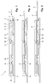
- reference number 1 denotes a card reader, in the direction of insertion 2 via a mouthpiece 3 two cards 4 and 5, hereinafter referred to as chip cards ( Figures 2 and 3) can be introduced.
- Insertion slot 9 corresponds to the common strength of the two chip cards 4, 5, one due to the insertion slot 9 elastic claws that delimit at the top 8 the height of the insertion slot 9 is also somewhat lower chosen as the common strength of the two chip cards 4, 5 can be.
- the two chip cards are in the card reader 1 itself 4, 5 guided over lateral guides 10 (Fig. 4).
- the chip cards 4, 5 each carry an integrated one Circuit (not shown), with exposed contact areas 11, 12 on the chip card 4, 5 each exchange information allow with the integrated circuit.
- a first (rear) reading unit 13 in the card reader 1 Contact springs 14 are provided which the contact surfaces 11 of the can contact the first chip card 4 and via contact connections 15 can be connected with appropriate electronics.
- a second (front) reading unit 16 with contact springs 17 provided, via which the contact surfaces 12 of the second card 5 can be contacted electrically and the are connected to contact terminals 18.
- the card reader 1 enables the exchange of information with the second chip card 5 only if the first chip card 4 is already inserted in their reading position.
- the first chip card 4 in the insertion direction 2 via the mouthpiece 3 into the insertion slot 9, which is inside the front reading unit 16 is provided up to the first reading unit 13 inserted.
- the chip card 4 is within the second Reading unit 16 via a lower and upper insertion slope 19, 20 inserted into a narrower insertion slot 21, whose height is approximately the card strength of the first chip card 4 corresponds.
- the first chip card 4 is inserted further with the help of a displaceable in the direction of insertion 2 and in the direction of the contact springs 14 lowerable guide carriage 22 (FIG. 4), in the lateral guides 23 is guided, lowered on the contact springs 14 until the Chip card 4 in its reading position at a rear stop 24 of the card reader 1 strikes.
- the second chip card 5 below the first chip card 4 via the mouthpiece 3 in the insertion direction 2 inserted into the card reader 1, being between the lower Insertion bevel 6 and the first chip card 4 in the remaining Insertion slot 9 in the front reading unit 16 is inserted.
- the second chip card 5 reaches its reading position, if they are at a rear stop 26 in the front reading unit 16 strikes. If the height of the insertion slot 9 less than the common card strength is both chip cards 4, 5, the second card 5 through the elastic crossbar 8 in the direction of their contact springs 17 pressed.
- the first card 4 in the area of the front reading unit 16 in the insertion direction 2 is guided obliquely downwards on their contact springs 14, can the insertion slot 9 narrowed in the insertion direction 2 and so the second card 5 is loaded with force on its contact springs 17 become.
- a rear presence sensor 25 (FIG. 4) is triggered when the first chip card 4 is inserted into its reading position is.
- one for the second chip card 5 provided front presence sensor 27 is actuated, when the second chip card 5 is inserted into its reading position is.
- this is the front presence sensor 27 for the second chip card 5 (and accordingly the rear presence sensor 25 for the first chip card 4) formed by two contact springs 28, one of which is in the The path of movement of the second chip card 5 protrudes.
- By pushing in the second chip card 5 becomes a contact spring 28 pushed out of contact and thereby contacted the other contact spring 28.
- each Recesses 30 and 31 are provided for impairment of the insertion process through raised embossments to prevent the surface of the two chip cards 4, 5.
- the second card 5 is inserted when the first Card 4 has not previously been inserted into card reader 1 is, the second card 5 is in the data exchange position for the first card 4, i.e. into the reading unit 13, inserted in the card reader 1. If this is the first card inserted second card 5 no corresponding authorization data contains one afterwards in the card reader 1 inserted card with the front reader 16 not read become.
Landscapes
- Engineering & Computer Science (AREA)
- Artificial Intelligence (AREA)
- Computer Vision & Pattern Recognition (AREA)
- Physics & Mathematics (AREA)
- General Physics & Mathematics (AREA)
- Theoretical Computer Science (AREA)
- Coupling Device And Connection With Printed Circuit (AREA)
Claims (4)
- Lecteur de cartes (1) destiné à échanger des données avec des cartes (4, 5), qui portent un circuit intégré, comportant deux unités (13, 16) d'échange de données pour deux cartes (4, 5) pouvant être introduites dans le lecteur de cartes (1), et dans lequel lorsque la seconde carte (5) est dans sa position d'échange de données, elle est guidée, et de préférence chargée par une force, par la première carte (4) introduite auparavant dans sa position d'échange de données, et dans lequel la première unité (13) d'échange de données pour la première carte (4) est disposée en arrière de la seconde unité (16) d'échange de données pour la seconde carte (5), dans la direction d'introduction (2) des cartes (4, 5), et la seconde unité (16) d'échange de données comporte des ressorts de contact (17), qui pénètrent dans la fente d'introduction (9) prévue pour les deux cartes (4, 5) et qui, lors de l'introduction de la seconde carte (5), glissent au-dessus de cette dernière et de ses ressorts de contact (12),
caractérisé en ce que
la première unité (13) d'échange de données comporte un curseur de guidage (22), qui est déplaçable dans la direction d'introduction (2) et peut être abaissé en direction des ressorts de contact (14) de la première unité (13) d'échange de données, pour abaisser la carte (4), pour l'échange de données, sur les ressorts de contact (14). - Lecteur de cartes selon la revendication 1, caractérisé en ce que la hauteur de la fente d'introduction (9) commune pour les deux cartes (4, 5) peut être augmentée, de façon élastique, à une valeur égale à l'épaisseur conjointe des deux cartes (4, 5).
- Lecteur de cartes selon la revendication 1 ou 2, caractérisé en ce que pour l'introduction de la première carte (4) dans la fente d'introduction (21) dont la hauteur est réduite, il est prévu au moins un biseau d'introduction (19, 20).
- Lecteur de cartes selon l'une des revendications précédentes, caractérisé en ce que chaque unité (13, 16) d'échange de données possède un capteur (25, 27) de la présence d'une carte.
Applications Claiming Priority (2)
| Application Number | Priority Date | Filing Date | Title |
|---|---|---|---|
| DE19719003A DE19719003A1 (de) | 1997-05-06 | 1997-05-06 | Kartenleser |
| DE19719003 | 1997-05-06 |
Publications (2)
| Publication Number | Publication Date |
|---|---|
| EP0877332A1 EP0877332A1 (fr) | 1998-11-11 |
| EP0877332B1 true EP0877332B1 (fr) | 2001-02-28 |
Family
ID=7828707
Family Applications (1)
| Application Number | Title | Priority Date | Filing Date |
|---|---|---|---|
| EP98107689A Expired - Lifetime EP0877332B1 (fr) | 1997-05-06 | 1998-04-28 | Lecteur de cartes à puce |
Country Status (2)
| Country | Link |
|---|---|
| EP (1) | EP0877332B1 (fr) |
| DE (2) | DE19719003A1 (fr) |
Citations (1)
| Publication number | Priority date | Publication date | Assignee | Title |
|---|---|---|---|---|
| DE3931508A1 (de) * | 1989-09-21 | 1991-04-25 | Amphenol Tuchel Elect | Chipkartenleser |
Family Cites Families (3)
| Publication number | Priority date | Publication date | Assignee | Title |
|---|---|---|---|---|
| FR2728709B1 (fr) * | 1994-07-13 | 1997-01-24 | Schlumberger Ind Sa | Interface portable pour carte a puce electronique |
| JP3559319B2 (ja) * | 1994-09-29 | 2004-09-02 | 株式会社東芝 | Icカード情報処理装置 |
| GB2298743B (en) * | 1995-03-10 | 1998-10-14 | Kenven Developments Limited | A connector for making surface electrical connections to IC cards |
-
1997
- 1997-05-06 DE DE19719003A patent/DE19719003A1/de not_active Ceased
-
1998
- 1998-04-28 DE DE59800489T patent/DE59800489D1/de not_active Expired - Fee Related
- 1998-04-28 EP EP98107689A patent/EP0877332B1/fr not_active Expired - Lifetime
Patent Citations (1)
| Publication number | Priority date | Publication date | Assignee | Title |
|---|---|---|---|---|
| DE3931508A1 (de) * | 1989-09-21 | 1991-04-25 | Amphenol Tuchel Elect | Chipkartenleser |
Also Published As
| Publication number | Publication date |
|---|---|
| EP0877332A1 (fr) | 1998-11-11 |
| DE59800489D1 (de) | 2001-04-05 |
| DE19719003A1 (de) | 1998-11-12 |
Similar Documents
| Publication | Publication Date | Title |
|---|---|---|
| DE3625306C2 (fr) | ||
| DE4118312C2 (de) | Kontaktsatz für eine Kontaktzonen aufweisende Karte | |
| DE3804361C1 (fr) | ||
| DE3645268C2 (de) | Kartenaufnehmner für ein Lesegerät für eine Chip-Karte | |
| DE19829551C2 (de) | Kontaktträger | |
| DE69325686T2 (de) | Magnetische und optische Koden-Leseeinrichtung | |
| DE3810274A1 (de) | Chipkarten-kontaktiereinrichtung | |
| DE68918145T2 (de) | Kartensteckverbinder. | |
| DE3813379A1 (de) | Perforationszange | |
| EP0877332B1 (fr) | Lecteur de cartes à puce | |
| EP1363226A1 (fr) | Lecteur de cartes | |
| EP0826186A1 (fr) | Carte a puce et lecteur de carte a puce | |
| DE278950T1 (de) | Datentraeger und lesegeraet sowie verfahren zur kontrolle eines schluessels. | |
| DE19731380C2 (de) | Sicherheits-Matrix für eine Mehrzahl von Sicherheitslogik-Chipkarten | |
| CH651406A5 (de) | Berechtigungskarte. | |
| DE3608275A1 (de) | Geraet zum lesen einer datenspur einer karte | |
| DE102010030733B4 (de) | Kartenleser mit Entladungskontakten | |
| DE29723669U1 (de) | Kartenleser | |
| DE19606692A1 (de) | Überwachter 3-Ebenen Hybridleser (Maresch-Leser) | |
| EP0976083B1 (fr) | Dispositif de lecture de cartes a puce | |
| EP0400538A2 (fr) | Dispositif de lecture pour cartes à puce | |
| DE3437030A1 (de) | Kopiergeschuetzter schluessel und codiertes lesegeraet fuer elektronische schliess-systeme | |
| EP0833272A2 (fr) | Lecteur de carte à puce | |
| DE3813380C2 (de) | Kärtchen zum Lochen für Abrechnungszwecke | |
| DE9200961U1 (de) | Druckluftnagler |
Legal Events
| Date | Code | Title | Description |
|---|---|---|---|
| PUAI | Public reference made under article 153(3) epc to a published international application that has entered the european phase |
Free format text: ORIGINAL CODE: 0009012 |
|
| AK | Designated contracting states |
Kind code of ref document: A1 Designated state(s): DE FR GB |
|
| AX | Request for extension of the european patent |
Free format text: AL;LT;LV;MK;RO;SI |
|
| 17P | Request for examination filed |
Effective date: 19990206 |
|
| 17Q | First examination report despatched |
Effective date: 19990503 |
|
| AKX | Designation fees paid |
Free format text: DE FR GB |
|
| GRAG | Despatch of communication of intention to grant |
Free format text: ORIGINAL CODE: EPIDOS AGRA |
|
| GRAG | Despatch of communication of intention to grant |
Free format text: ORIGINAL CODE: EPIDOS AGRA |
|
| GRAH | Despatch of communication of intention to grant a patent |
Free format text: ORIGINAL CODE: EPIDOS IGRA |
|
| GRAH | Despatch of communication of intention to grant a patent |
Free format text: ORIGINAL CODE: EPIDOS IGRA |
|
| GRAA | (expected) grant |
Free format text: ORIGINAL CODE: 0009210 |
|
| AK | Designated contracting states |
Kind code of ref document: B1 Designated state(s): DE FR GB |
|
| PG25 | Lapsed in a contracting state [announced via postgrant information from national office to epo] |
Ref country code: GB Free format text: LAPSE BECAUSE OF FAILURE TO SUBMIT A TRANSLATION OF THE DESCRIPTION OR TO PAY THE FEE WITHIN THE PRESCRIBED TIME-LIMIT Effective date: 20010228 |
|
| REF | Corresponds to: |
Ref document number: 59800489 Country of ref document: DE Date of ref document: 20010405 |
|
| ET | Fr: translation filed | ||
| GBV | Gb: ep patent (uk) treated as always having been void in accordance with gb section 77(7)/1977 [no translation filed] |
Effective date: 20010228 |
|
| PLBE | No opposition filed within time limit |
Free format text: ORIGINAL CODE: 0009261 |
|
| STAA | Information on the status of an ep patent application or granted ep patent |
Free format text: STATUS: NO OPPOSITION FILED WITHIN TIME LIMIT |
|
| 26N | No opposition filed | ||
| PGFP | Annual fee paid to national office [announced via postgrant information from national office to epo] |
Ref country code: DE Payment date: 20080429 Year of fee payment: 11 |
|
| PGFP | Annual fee paid to national office [announced via postgrant information from national office to epo] |
Ref country code: FR Payment date: 20080418 Year of fee payment: 11 |
|
| REG | Reference to a national code |
Ref country code: FR Ref legal event code: ST Effective date: 20091231 |
|
| PG25 | Lapsed in a contracting state [announced via postgrant information from national office to epo] |
Ref country code: DE Free format text: LAPSE BECAUSE OF NON-PAYMENT OF DUE FEES Effective date: 20091103 |
|
| PG25 | Lapsed in a contracting state [announced via postgrant information from national office to epo] |
Ref country code: FR Free format text: LAPSE BECAUSE OF NON-PAYMENT OF DUE FEES Effective date: 20091222 |