EP0877412A1 - Lampe à électrode ou traversée centrée et son procédé de fabrication - Google Patents
Lampe à électrode ou traversée centrée et son procédé de fabrication Download PDFInfo
- Publication number
- EP0877412A1 EP0877412A1 EP98106595A EP98106595A EP0877412A1 EP 0877412 A1 EP0877412 A1 EP 0877412A1 EP 98106595 A EP98106595 A EP 98106595A EP 98106595 A EP98106595 A EP 98106595A EP 0877412 A1 EP0877412 A1 EP 0877412A1
- Authority
- EP
- European Patent Office
- Prior art keywords
- arc tube
- longitudinal axis
- depression
- press
- feet
- Prior art date
- Legal status (The legal status is an assumption and is not a legal conclusion. Google has not performed a legal analysis and makes no representation as to the accuracy of the status listed.)
- Withdrawn
Links
- 238000004519 manufacturing process Methods 0.000 title description 2
- 239000011888 foil Substances 0.000 claims abstract description 20
- ZOKXTWBITQBERF-UHFFFAOYSA-N Molybdenum Chemical compound [Mo] ZOKXTWBITQBERF-UHFFFAOYSA-N 0.000 claims abstract description 7
- 229910052750 molybdenum Inorganic materials 0.000 claims abstract description 7
- 239000011733 molybdenum Substances 0.000 claims abstract description 7
- 238000007789 sealing Methods 0.000 claims description 17
- 238000010438 heat treatment Methods 0.000 claims description 6
- 238000010891 electric arc Methods 0.000 claims description 5
- 239000000463 material Substances 0.000 claims description 5
- 239000002775 capsule Substances 0.000 claims description 4
- 238000000034 method Methods 0.000 claims description 3
- 238000003466 welding Methods 0.000 abstract description 3
- 239000010453 quartz Substances 0.000 description 5
- VYPSYNLAJGMNEJ-UHFFFAOYSA-N silicon dioxide Inorganic materials O=[Si]=O VYPSYNLAJGMNEJ-UHFFFAOYSA-N 0.000 description 5
- WFKWXMTUELFFGS-UHFFFAOYSA-N tungsten Chemical compound [W] WFKWXMTUELFFGS-UHFFFAOYSA-N 0.000 description 4
- 229910052721 tungsten Inorganic materials 0.000 description 4
- 239000010937 tungsten Substances 0.000 description 4
- 239000000126 substance Substances 0.000 description 3
- 241001279686 Allium moly Species 0.000 description 2
- 230000000712 assembly Effects 0.000 description 2
- 238000000429 assembly Methods 0.000 description 2
- 229910001507 metal halide Inorganic materials 0.000 description 2
- 150000005309 metal halides Chemical class 0.000 description 2
- 238000013021 overheating Methods 0.000 description 2
- DGAQECJNVWCQMB-PUAWFVPOSA-M Ilexoside XXIX Chemical compound C[C@@H]1CC[C@@]2(CC[C@@]3(C(=CC[C@H]4[C@]3(CC[C@@H]5[C@@]4(CC[C@@H](C5(C)C)OS(=O)(=O)[O-])C)C)[C@@H]2[C@]1(C)O)C)C(=O)O[C@H]6[C@@H]([C@H]([C@@H]([C@H](O6)CO)O)O)O.[Na+] DGAQECJNVWCQMB-PUAWFVPOSA-M 0.000 description 1
- 230000015572 biosynthetic process Effects 0.000 description 1
- 230000002860 competitive effect Effects 0.000 description 1
- 230000005494 condensation Effects 0.000 description 1
- 238000009833 condensation Methods 0.000 description 1
- 230000003247 decreasing effect Effects 0.000 description 1
- 238000010586 diagram Methods 0.000 description 1
- 239000003779 heat-resistant material Substances 0.000 description 1
- 229910052751 metal Inorganic materials 0.000 description 1
- 239000002184 metal Substances 0.000 description 1
- 238000012986 modification Methods 0.000 description 1
- 230000004048 modification Effects 0.000 description 1
- 238000003825 pressing Methods 0.000 description 1
- 229910052706 scandium Inorganic materials 0.000 description 1
- -1 scandium halides Chemical class 0.000 description 1
- 238000004904 shortening Methods 0.000 description 1
- 229910052708 sodium Inorganic materials 0.000 description 1
- 239000011734 sodium Substances 0.000 description 1
Images

Classifications
-
- H—ELECTRICITY
- H01—ELECTRIC ELEMENTS
- H01J—ELECTRIC DISCHARGE TUBES OR DISCHARGE LAMPS
- H01J61/00—Gas-discharge or vapour-discharge lamps
- H01J61/02—Details
- H01J61/36—Seals between parts of vessels; Seals for leading-in conductors; Leading-in conductors
- H01J61/366—Seals for leading-in conductors
- H01J61/368—Pinched seals or analogous seals
-
- H—ELECTRICITY
- H01—ELECTRIC ELEMENTS
- H01J—ELECTRIC DISCHARGE TUBES OR DISCHARGE LAMPS
- H01J61/00—Gas-discharge or vapour-discharge lamps
- H01J61/02—Details
- H01J61/30—Vessels; Containers
- H01J61/34—Double-wall vessels or containers
-
- H—ELECTRICITY
- H01—ELECTRIC ELEMENTS
- H01J—ELECTRIC DISCHARGE TUBES OR DISCHARGE LAMPS
- H01J9/00—Apparatus or processes specially adapted for the manufacture, installation, removal, maintenance of electric discharge tubes, discharge lamps, or parts thereof; Recovery of material from discharge tubes or lamps
- H01J9/24—Manufacture or joining of vessels, leading-in conductors or bases
- H01J9/32—Sealing leading-in conductors
- H01J9/323—Sealing leading-in conductors into a discharge lamp or a gas-filled discharge device
- H01J9/326—Sealing leading-in conductors into a discharge lamp or a gas-filled discharge device making pinched-stem or analogous seals
Definitions
- This invention relates to lamps and more particularly to lamps having improved performance. Still more particularly, it relates to lamps having improved electrode centering whereby the wall temperatures encountered in the electrode area are substantially uniform.
- High intensity discharge lamps including those of the metal halide variety, provide light by the generation of an electric arc occurring in an evacuated arc chamber provided with light emitting materials such as sodium and scandium halides.
- the arc chamber or arc tube is formed from quartz and the electrodes are usually tungsten.
- the arc tube is sealed around the electrodes by means of a press seal, formed by heating the end of the arc tube to a plastic condition with the electrode held in a desired position, and literally pressing the ends of the cylinder together.
- the quartz forms around the tungsten electrode, as well as a lead-in pin extending outside of the arc tube, the hermetic seal itself is made at the moly foil.
- the electrodes be closely aligned with the longitudinal axis of the arc tube. This can be difficult to accomplish because of the varying geometries of the components; for example., the moly foil is a thin, flat ribbon and the electrodes and the lead-ins are generally cylindrical.
- an arc tube which comprises an hermetically sealed discharge chamber having a longitudinal axis and containing an arc generating and sustaining medium.
- the chamber has oppositely disposed sealed ends, each of which sealed ends comprises a substantially parallelepipodonal structure having two oppositely disposed planar sides.
- a molybdenum foil is sealed in each of the ends, centrally located between the planar sides.
- An in-lead is connected to the foil and extends externally of the seal, and an electrode is connected to the foil and extends into the discharge chamber.
- a boss is formed on one of the planar sides and a depression is formed on the other of the planar sides, the boss and the depression cooperating to center the electrodes on the longitudinal axis of the discharge chamber within plus or minus ⁇ 1°.
- the arc tube is manufactured by a method of sealing an arc tube which has a longitudinal axis by the steps of: positioning an end of an arc tube blank at a sealing station; positioning an electrode assembly comprised of an electrode, a sealing foil, and an in-lead in a desired position within the blank; heating the end of the arc tube blank to a plastic state; and forming a press-seal at the end of the blank by engaging the now plastic end with a pair of oppositely disposed press-mold feet, a first of the press-mold feet having a depression aligned along the longitudinal axis and a second of the press-mold feet having a protuberance aligned along the longitudinal axis opposite the depression; and causing the press-mold feet to approach each other to squeeze the plastic material of the end together and form the seal.
- the objects of the invention are easily accomplished without any additional manufacturing steps being performed, thereby resulting in an improved arc tube at no additional cost.
- Fig. 1 an exemplary metal halide arc discharge lamp 10 including a lamp envelope 12 and an arc tube 14 mounted within the envelope by mounting frame 16.
- the arc tube may be positioned within a shroud 20 which can also be supported by the mounting frame 16. Electrical energy is coupled to the arc tube 14 through a base 22, a lamp stem 24 and electrical leads 26 and 28.
- the arc tube contains a chemical fill or dose of materials to provide light when an arc is initiated therein, as is known.
- the shroud 20 comprises a cylindrical tube of light transmissive, heat resistant material such as quartz.
- the mounting frame 16 supports both the arc tube 14 and the shroud 20 within the lamp envelope 12.
- the mounting frame 16 includes a metal support rod 30 attached to lamp stem 24 by a strap 31.
- the support rod engages an inward projection 32 in the upper end of the lamp envelope 12.
- the support rod 30 in its central portion is parallel to a central axis of the arc tube 14 and shroud 20.
- the mounting means 16 further includes an upper clip 40 and a lower clip 42 which secure both arc tube 14 and shroud 20 to support rod 30.
- the clips 40 and 42 are attached to the support rod 30, preferably by welding.
- Each electrode assembly 44 comprises an electrode 46 of a suitable material, such as tungsten, and may a have coil 48 attached to one end thereof, internally of the arc tube; a molybdenum sealing foil 50 attached to the other end of the electrode; and an in-lead 52 attached to the opposite end of the molybdenum sealing foil and extending externally of the arc tube for making electrical connection thereto.
- the electrode assemblies are more clearly seen in Figs. 2-8.
- One of the in-leads 52 is connected to electrical lead 26 and one is connected to electrical lead 28.
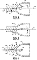
- prior art arc tubes 14 had a press-seal 43 having a substantially parallelepipodonal structure 54 having two oppositely disposed planar sides 56 and 58, and, after sealing, had the electrode 46 displaced from the longitudinal axis 60 an angle ⁇ which was approximately 5°.
- Figs. 3 and 5 illustrate an improvement, wherein the press-seal 43 was provided with a rod-relief mechanism 62 in the form of a raised protuberance 64.
- the rod-relief mechanism 62 caused some improvement, resulting in a deviation from the longitudinal axis measured by the angle ⁇ , which approximated about 3°.
- FIG. 4 An embodiment of the invention is shown in Fig. 4 wherein an hermetically sealed arc tube 14 has a longitudinal axis 60 and contains therewithin an arc generating ad sustaining medium, as is known.
- the ends of the arc tube 14 are sealed with press-seals 43 (only one of which is shown in Figs. 2-8).
- the seals comprise a substantially parallelepipodonal structure having oppositely disposed, planar sides 56 and 58.
- a molybdenum foil 50 is sealed in each of the press-seals and is substantially centrally located between the planar sides 56 and 58.
- An in-lead 52 is secured as by welding to an end of foil 50 and extends outwardly of the arc tube for electrical connection to a source and an electrode 46 is attached to the other end of foil 50 and projects into the arc chamber.
- a first rod-relief member 62 in the form of a projecting boss 64 is formed on one of the planar sides, for example, 58, and a second rod-relief member 66 in the form of a depression 68 is formed on the other of the planar sides, in this instance side 56.
- the rod-relief members cooperate to center the electrode on the longitudinal axis within a variance of ⁇ 1°, a vast improvement over the prior art.
- first rod-relief member 62 takes the form of an elongated protrusion which is parallel to the longitudinal axis 60
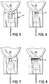
- the second rod-relief member can be frusto-conical, as shown at 70 in Fig. 6; hemispherical, as shown at 72 in Fig. 7; or elongated and transverse to the first member, as shown at 74 in Fig. 8.
- the first rod-relief member 62 has a length of about 0.165" (0.42cm), a width of about 0.060" (0.15cm) and a depth of about 0.015" (0.04cm).
- the second rod-relief member 66 has, in the case of the hemispherical depression 72, a diameter of about 0.035" (0.09cm) and a depth of about 0.010" (0.025cm); in the case of the frusto-conical depression 70 a major diameter of 0.035" and a depth of 0.010"; and in the case of the elongated member 74 a width of 0.035", a depth of 0.010" and a length is less than the width of the press-seal. As a minimum, the length is preferably about 0.035".
- a pair of cooperating press-mold sealing feet 76 and 78, for forming press seals in arc discharge lamps is shown in Fig. 9.
- Each of the feet has a substantially planar sealing surface 80, 82, respectively.
- Foot 76 contains a depression 84 in the planar surface arrayed along a longitudinal axis thereof. During seal formation this depression will form the first rod-relief member 62.
- the second foot 78 has a protuberance 86 formed on its planar surface 80, this protuberance being opposite the depression and functioning to form the second rod-relief member during the sealing operation.
- the protuberance illustrated is for forming the elongated member 74, it will be apparent to those skilled in the art that the hemispherical depression 72 and the frusto-conical depression 70 will take the appropriate form. Other forms, of course, are possible, such as square or pyramidal, and may be dictated by the size of the arc lamp.
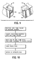
- the seals are formed by positioning an arc tube blank at a sealing station and then inserting an electrode assembly thereinto.
- the end of the blank is heated to a plastic state and the press seal is formed by actuating the press-mold sealing feet.
- the sealing operations may be performed simultaneously at both ends of the arc tube or sequentially.
- Arc tubes thus formed have longitudinally aligned electrodes which provide more efficient operation of the lamps with which they are employed.
- the solution is economical and consistent, requiring no additional forming steps to be performed upon the electrodes themselves.
- the invention is also operable with incandescent lamps having a light source capsule containing a filament supported by in-leads extending externally of the seal and internally of the capsule.
Landscapes
- Engineering & Computer Science (AREA)
- Manufacturing & Machinery (AREA)
- Vessels And Coating Films For Discharge Lamps (AREA)
- Manufacture Of Electron Tubes, Discharge Lamp Vessels, Lead-In Wires, And The Like (AREA)
- Discharge Lamp (AREA)
- Tubes (AREA)
Applications Claiming Priority (2)
| Application Number | Priority Date | Filing Date | Title |
|---|---|---|---|
| US850793 | 1986-04-11 | ||
| US08/850,793 US5834897A (en) | 1997-05-02 | 1997-05-02 | Lamp with centered electrode or in-lead |
Publications (1)
| Publication Number | Publication Date |
|---|---|
| EP0877412A1 true EP0877412A1 (fr) | 1998-11-11 |
Family
ID=25309126
Family Applications (1)
| Application Number | Title | Priority Date | Filing Date |
|---|---|---|---|
| EP98106595A Withdrawn EP0877412A1 (fr) | 1997-05-02 | 1998-04-09 | Lampe à électrode ou traversée centrée et son procédé de fabrication |
Country Status (6)
| Country | Link |
|---|---|
| US (1) | US5834897A (fr) |
| EP (1) | EP0877412A1 (fr) |
| JP (1) | JPH10312774A (fr) |
| KR (1) | KR19980086703A (fr) |
| CA (1) | CA2226827A1 (fr) |
| HU (1) | HU218959B (fr) |
Cited By (3)
| Publication number | Priority date | Publication date | Assignee | Title |
|---|---|---|---|---|
| EP1143484A1 (fr) * | 2000-04-03 | 2001-10-10 | Matsushita Electric Industrial Co., Ltd. | Lampe à décharge et unité de lampe |
| EP1737020A3 (fr) * | 2005-06-20 | 2007-07-11 | Osram Sylvania Inc. | Ampoule à décharge à culot unique avec des électrodes divergentes |
| DE10031182B4 (de) * | 1999-06-28 | 2007-11-22 | Koito Manufacturing Co., Ltd. | Bogenentladungsröhre mit Restdruckbelastungsschicht für eine Entladungslampeneinheit und Verfahren zur Herstellung derselben |
Citations (2)
| Publication number | Priority date | Publication date | Assignee | Title |
|---|---|---|---|---|
| GB808933A (en) * | 1956-10-09 | 1959-02-11 | Gen Electric Co Ltd | Improvements in or relating to vitreous-to-metal pinch seals |
| EP0061757A2 (fr) * | 1981-03-31 | 1982-10-06 | Patent-Treuhand-Gesellschaft für elektrische Glühlampen mbH | Méthode pour sceller par pincement une lampe éléctrique et dispositif de pincement pour la mise en oeuvre de cette méthode |
Family Cites Families (15)
| Publication number | Priority date | Publication date | Assignee | Title |
|---|---|---|---|---|
| US2273450A (en) * | 1934-03-09 | 1942-02-17 | Westinghouse Lamp Co | High pressure metal vapor lamp |
| US3548245A (en) * | 1969-02-13 | 1970-12-15 | Gen Electric | Quartz-to-metal foil pinch seal |
| US3742283A (en) * | 1971-10-28 | 1973-06-26 | Gte Sylvania Inc | Press seal for lamp having fused silica envelope |
| US3912960A (en) * | 1974-06-21 | 1975-10-14 | Gen Electric | Halogen lamp with internal molybdenum parts |
| US4396857A (en) * | 1980-07-01 | 1983-08-02 | General Electric Company | Arc tube construction |
| US5087218A (en) * | 1985-11-15 | 1992-02-11 | General Electric Company | Incandesent lamps and processes for making same |
| US4891554A (en) * | 1988-10-31 | 1990-01-02 | General Electric Company | Arc discharge lamp having improved performance |
| US4916353A (en) * | 1989-02-28 | 1990-04-10 | General Electric Company | Incandescent lamp utilizing cylindrical transparent heat mirror |
| US5252885A (en) * | 1989-12-11 | 1993-10-12 | Gte Products Corporation | Metal halide arc discharge lamp assembly |
| EP0451647B1 (fr) * | 1990-04-12 | 1995-07-05 | Patent-Treuhand-Gesellschaft für elektrische Glühlampen mbH | Lampe à décharge à haute pression et son procédé de fabrication |
| US5471110A (en) * | 1991-12-23 | 1995-11-28 | Philips Electronics North America Corporation | High pressure discharge lamp having filament electrodes |
| US5374872A (en) * | 1992-11-13 | 1994-12-20 | General Electric Company | Means for supporting and sealing the lead structure of a lamp and method for making such lamp |
| US5387839A (en) * | 1992-12-11 | 1995-02-07 | General Electric Company | Electrode-inlead assembly for electrical lamps |
| DE4242122A1 (de) * | 1992-12-14 | 1994-06-16 | Patent Treuhand Ges Fuer Elektrische Gluehlampen Mbh | Verfahren zur Herstellung einer vakuumdichten Abdichtung zwischen einem keramischen und einem metallischen Partner, insbesondere zur Anwendung bei der Herstellung eines Entladungsgefäßes für eine Lampe, sowie damit hergestellte Entladungsgefäße und Lampen |
| US5457354A (en) * | 1994-09-26 | 1995-10-10 | Osram Sylvania Inc. | Lamp with improved mount for light-source capsule |
-
1997
- 1997-05-02 US US08/850,793 patent/US5834897A/en not_active Expired - Fee Related
-
1998
- 1998-01-13 CA CA002226827A patent/CA2226827A1/fr not_active Abandoned
- 1998-04-09 EP EP98106595A patent/EP0877412A1/fr not_active Withdrawn
- 1998-04-30 HU HU9801015A patent/HU218959B/hu not_active IP Right Cessation
- 1998-05-01 JP JP10122167A patent/JPH10312774A/ja active Pending
- 1998-05-01 KR KR1019980015756A patent/KR19980086703A/ko not_active Withdrawn
Patent Citations (2)
| Publication number | Priority date | Publication date | Assignee | Title |
|---|---|---|---|---|
| GB808933A (en) * | 1956-10-09 | 1959-02-11 | Gen Electric Co Ltd | Improvements in or relating to vitreous-to-metal pinch seals |
| EP0061757A2 (fr) * | 1981-03-31 | 1982-10-06 | Patent-Treuhand-Gesellschaft für elektrische Glühlampen mbH | Méthode pour sceller par pincement une lampe éléctrique et dispositif de pincement pour la mise en oeuvre de cette méthode |
Cited By (5)
| Publication number | Priority date | Publication date | Assignee | Title |
|---|---|---|---|---|
| DE10031182B4 (de) * | 1999-06-28 | 2007-11-22 | Koito Manufacturing Co., Ltd. | Bogenentladungsröhre mit Restdruckbelastungsschicht für eine Entladungslampeneinheit und Verfahren zur Herstellung derselben |
| EP1143484A1 (fr) * | 2000-04-03 | 2001-10-10 | Matsushita Electric Industrial Co., Ltd. | Lampe à décharge et unité de lampe |
| US6876151B2 (en) | 2000-04-03 | 2005-04-05 | Matsushita Electric Industrial Co., Ltd. | Discharge lamp and lamp unit |
| EP1737020A3 (fr) * | 2005-06-20 | 2007-07-11 | Osram Sylvania Inc. | Ampoule à décharge à culot unique avec des électrodes divergentes |
| US7414366B2 (en) | 2005-06-20 | 2008-08-19 | Osram Sylvania Inc. | Single-ended discharge vessel with diverging electrodes |
Also Published As
| Publication number | Publication date |
|---|---|
| HU9801015D0 (en) | 1998-06-29 |
| HUP9801015A3 (en) | 1999-03-01 |
| HUP9801015A2 (hu) | 1998-12-28 |
| HU218959B (hu) | 2001-01-29 |
| US5834897A (en) | 1998-11-10 |
| JPH10312774A (ja) | 1998-11-24 |
| CA2226827A1 (fr) | 1998-11-02 |
| KR19980086703A (ko) | 1998-12-05 |
Similar Documents
| Publication | Publication Date | Title |
|---|---|---|
| US5598063A (en) | Means for supporting and sealing the lead structure of a lamp | |
| JP2000277052A (ja) | 口金付高圧放電ランプ | |
| US6249077B1 (en) | Arc tube, mounting member and electric lamp assembly | |
| JP3461534B2 (ja) | 高圧放電ランプ | |
| JPH0421984B2 (fr) | ||
| US4481443A (en) | Short-arc discharge lamp | |
| US5834897A (en) | Lamp with centered electrode or in-lead | |
| US4469983A (en) | Electric lamp with an envelope seal designed as pinch seal, and a device and method for its manufacture | |
| US6786791B2 (en) | Quartz arc tube for a metal halide lamp and method of making same | |
| JP5214445B2 (ja) | モリブデン−レニウム端部キャップを有するセラミックランプ、並びに該ランプを備えるシステム及び方法 | |
| US2845557A (en) | Arc tube mounting | |
| US5343117A (en) | Electrode feedthrough connection strap for arc discharge lamp | |
| JP3498072B2 (ja) | 放電ランプ用発光体 | |
| US5211595A (en) | Method of manufacturing an arc tube with offset press seals | |
| US3219870A (en) | High pressure discharge lamps seal and base | |
| US7619350B2 (en) | Arc discharge vessel having arc centering structure and lamp containing same | |
| JP2005183267A (ja) | ランプ | |
| US6100634A (en) | Method for amalgam relocation in an arc discharge tube | |
| KR100434194B1 (ko) | 방전램프용 발광체 | |
| JPH0660960U (ja) | ランプ | |
| JP2006222086A (ja) | 石英及びセラミック発光管のためのシュラウドホルダ | |
| WO1991009416A1 (fr) | Jonction par sertissage de l'electrode au tube de traversee dans une lampe a decharge en arc | |
| JP3402465B2 (ja) | 放電管の製造法 | |
| JPS6398950A (ja) | 放電管 | |
| JPH01112634A (ja) | 閃光放電管の製造方法 |
Legal Events
| Date | Code | Title | Description |
|---|---|---|---|
| PUAI | Public reference made under article 153(3) epc to a published international application that has entered the european phase |
Free format text: ORIGINAL CODE: 0009012 |
|
| AK | Designated contracting states |
Kind code of ref document: A1 Designated state(s): BE DE FR GB IT NL |
|
| AX | Request for extension of the european patent |
Free format text: AL;LT;LV;MK;RO;SI |
|
| 17P | Request for examination filed |
Effective date: 19981105 |
|
| AKX | Designation fees paid |
Free format text: BE DE FR GB IT NL |
|
| 17Q | First examination report despatched |
Effective date: 20010305 |
|
| STAA | Information on the status of an ep patent application or granted ep patent |
Free format text: STATUS: THE APPLICATION HAS BEEN WITHDRAWN |
|
| 18W | Application withdrawn |
Withdrawal date: 20021121 |