EP0877457A1 - Installation de commutation électrique - Google Patents
Installation de commutation électrique Download PDFInfo
- Publication number
- EP0877457A1 EP0877457A1 EP98105065A EP98105065A EP0877457A1 EP 0877457 A1 EP0877457 A1 EP 0877457A1 EP 98105065 A EP98105065 A EP 98105065A EP 98105065 A EP98105065 A EP 98105065A EP 0877457 A1 EP0877457 A1 EP 0877457A1
- Authority
- EP
- European Patent Office
- Prior art keywords
- circuit
- line
- switch
- switchgear
- circuit breaker
- Prior art date
- Legal status (The legal status is an assumption and is not a legal conclusion. Google has not performed a legal analysis and makes no representation as to the accuracy of the status listed.)
- Withdrawn
Links
- 238000005192 partition Methods 0.000 description 3
- 238000010615 ring circuit Methods 0.000 description 3
- 238000000638 solvent extraction Methods 0.000 description 3
- 239000012212 insulator Substances 0.000 description 2
- 239000004020 conductor Substances 0.000 description 1
- 238000000926 separation method Methods 0.000 description 1
Images

Classifications
-
- H—ELECTRICITY
- H02—GENERATION; CONVERSION OR DISTRIBUTION OF ELECTRIC POWER
- H02B—BOARDS, SUBSTATIONS OR SWITCHING ARRANGEMENTS FOR THE SUPPLY OR DISTRIBUTION OF ELECTRIC POWER
- H02B1/00—Frameworks, boards, panels, desks, casings; Details of substations or switching arrangements
- H02B1/24—Circuit arrangements for boards or switchyards
Definitions
- the invention relates to an electrical switchgear according to the preamble of the claim 1.
- the H circuit with circuit breakers has four circuit breakers, one of which two are connected in series; the two current paths between the two circuit breakers each row are connected; in the connecting line there is a separator.
- the object of the invention is an electrical switchgear of the aforementioned Art to create with a minimal use of components and switchgear Maximum availability, operational safety and security of the personnel achieved becomes.
- two disconnectors between which the web can be earthed by means of an earthing switch.
- At least one of the disconnectors can be designed as a load disconnector.
- the double separation in the web enables a double if a stitch fails Isolating section with a grounded center; if an exit fails, then from the feeding transformer can also be fed into the parallel stitch. If is revised, there is an additional compartment in front of the device to be revised.
- the Circuit can be integrated in a ring circuit as well as for stub lines be used.
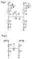
- the 1 has two branches I and II, each on one Transformer 10, 11 are connected. There are two in each of the two branches a current transformer 12, 13, each a circuit breaker 14, 15, each another circuit breaker 16, 17, one voltage converter 18, 19 each, one surge arrester 20, 21 and a further current transformer 22, 23 each. Thus there is a first one in the cable run I. Circuit breaker 14 and a second circuit breaker 16; in cable train II is a third circuit breaker 15 and a fourth circuit breaker 17 turned on. To the Line path 24 between the first and the second circuit breaker 16 closes a web 25 on, the other end in the conductor path 26 between the third and the fourth circuit breaker 15, 17 is connected. The web 25 contains in series a switch disconnector 27 and a so-called simple disconnector 28. Between the Both switches 27 and 28 are connected to an earthing line 29, in which an earthing switch 30, preferably a fast electrode 30 is switched on.
- the known arrangement shown in FIG. 3 has a partitioning space 40, in which is the one switch 41; this partition 40 is by means of two Bulkhead isolators 42 and 43 are partitioned off.
- this partition 40 is by means of two Bulkhead isolators 42 and 43 are partitioned off.
- 4 are two bulkhead spaces 44 and 45 with bulkhead isolators 46, 47, 48 and 49 provided; in addition there is a further partitioned space 50 between the two bulkhead insulators 47 and 48 in which the earthing switch 30 is located.
- the isolating switches 27 and 28 are located in the partitioning rooms 44 and 45. If the two circuit breakers 27 and 28 are open, then there is a revision of the switch 16, the two bulkhead insulators 47 and 48, so that thereby one double bulkheading with increased personnel security is achieved.
Landscapes
- Engineering & Computer Science (AREA)
- Power Engineering (AREA)
- Gas-Insulated Switchgears (AREA)
Applications Claiming Priority (2)
| Application Number | Priority Date | Filing Date | Title |
|---|---|---|---|
| DE1997119281 DE19719281A1 (de) | 1997-05-07 | 1997-05-07 | Elektrische Schaltanlage |
| DE19719281 | 1997-05-07 |
Publications (1)
| Publication Number | Publication Date |
|---|---|
| EP0877457A1 true EP0877457A1 (fr) | 1998-11-11 |
Family
ID=7828881
Family Applications (1)
| Application Number | Title | Priority Date | Filing Date |
|---|---|---|---|
| EP98105065A Withdrawn EP0877457A1 (fr) | 1997-05-07 | 1998-03-20 | Installation de commutation électrique |
Country Status (2)
| Country | Link |
|---|---|
| EP (1) | EP0877457A1 (fr) |
| DE (1) | DE19719281A1 (fr) |
Citations (4)
| Publication number | Priority date | Publication date | Assignee | Title |
|---|---|---|---|---|
| DE2632176A1 (de) * | 1976-07-16 | 1978-01-19 | Od Vi P Organizatsii Ener | Freiluftschaltanlage fuer hochspannung |
| US5216574A (en) * | 1991-07-23 | 1993-06-01 | Gec Alsthom Sa | Component for a metal-clad station for section switching and grounding |
| US5357068A (en) * | 1991-11-20 | 1994-10-18 | Gec Alsthom Sa | Sulfur hexafluoride isolating circuit-breaker and use thereof in prefabricated stations, substations, and bays |
| US5436797A (en) * | 1992-09-11 | 1995-07-25 | Gec Alsthom T & D Sa | Modular station of the metal-clad type and of reduced size, with a shortened set of busbars |
Family Cites Families (2)
| Publication number | Priority date | Publication date | Assignee | Title |
|---|---|---|---|---|
| DE2936075A1 (de) * | 1978-09-12 | 1980-04-30 | Vg P Izysk Nii Energet Sist | Hochspannungsschaltanlage |
| US4484086A (en) * | 1981-11-12 | 1984-11-20 | Bbc, Brown, Boveri & Company, Limited | Switching network |
-
1997
- 1997-05-07 DE DE1997119281 patent/DE19719281A1/de not_active Withdrawn
-
1998
- 1998-03-20 EP EP98105065A patent/EP0877457A1/fr not_active Withdrawn
Patent Citations (4)
| Publication number | Priority date | Publication date | Assignee | Title |
|---|---|---|---|---|
| DE2632176A1 (de) * | 1976-07-16 | 1978-01-19 | Od Vi P Organizatsii Ener | Freiluftschaltanlage fuer hochspannung |
| US5216574A (en) * | 1991-07-23 | 1993-06-01 | Gec Alsthom Sa | Component for a metal-clad station for section switching and grounding |
| US5357068A (en) * | 1991-11-20 | 1994-10-18 | Gec Alsthom Sa | Sulfur hexafluoride isolating circuit-breaker and use thereof in prefabricated stations, substations, and bays |
| US5436797A (en) * | 1992-09-11 | 1995-07-25 | Gec Alsthom T & D Sa | Modular station of the metal-clad type and of reduced size, with a shortened set of busbars |
Also Published As
| Publication number | Publication date |
|---|---|
| DE19719281A1 (de) | 1998-11-12 |
Similar Documents
| Publication | Publication Date | Title |
|---|---|---|
| DE2754691C2 (de) | Ein- oder mehrphasig metallgekapselte, druckgasisolierte Hochspannungsschaltanlage | |
| EP2151027B1 (fr) | Installation de distribution haute tension | |
| EP0069693B1 (fr) | Container cylindrique pour une installation haute tension blindée tripolaire à isolation gazeuse | |
| EP2572416B1 (fr) | Installation de commutation à isolation gazeuse | |
| DE102018203489A1 (de) | Wechselstromladevorrichtung für ein Kraftfahrzeug und Verfahren zum Betreiben einer Wechselstromladevorrichtung für ein Kraftfahrzeug | |
| EP1249910A2 (fr) | Disjoncteur haute-tension pour une installation de commutation à isolation gaseuse | |
| DE19805705A1 (de) | Gasisolierte metallgekapselte Schaltanlage | |
| EP1580856B1 (fr) | Poste à haute tension aérien | |
| DE3521945A1 (de) | Trennschalter fuer eine metallgekapselte, druckgasisolierte hochspannungsschaltanlage | |
| DE4233986C2 (de) | Schaltanlage mit Spannungswandler | |
| EP0582828B1 (fr) | Installation de distribution électrique | |
| EP0099970B1 (fr) | Switchgear | |
| EP0079628A1 (fr) | Installation de commutation | |
| DE102004061358B4 (de) | Hochspannungsschaltanlage | |
| EP0075967B1 (fr) | Installation de commutation | |
| DE3109669A1 (de) | Kombinationsbaustein (gehaeusebaustein) eines systems zum aufbau vollisolierter schaltanlagen | |
| EP0567773A2 (fr) | Système de commutation polyphasé et système générateur avec celui-ci | |
| EP0877457A1 (fr) | Installation de commutation électrique | |
| DE3732455C2 (fr) | ||
| DE2720325A1 (de) | Metallgekapselte, druckgasisolierte hochspannungsschaltanlage | |
| DE666199C (de) | Hochspannungsschaltanlage | |
| EP0995249A1 (fr) | Systeme de distribution electrique moyenne tension oriente besoins | |
| WO2008012012A1 (fr) | Module de barre collectrice pour une installation de distribution à haute tension isolée par gaz | |
| EP0217731B1 (fr) | Installation de commutation haute tension blindée à isolation gazeuse avec interrupteurs de mise à la terre | |
| WO2000033434A1 (fr) | Installations de distribution electrique comportant des sectionneurs de puissance |
Legal Events
| Date | Code | Title | Description |
|---|---|---|---|
| PUAI | Public reference made under article 153(3) epc to a published international application that has entered the european phase |
Free format text: ORIGINAL CODE: 0009012 |
|
| AK | Designated contracting states |
Kind code of ref document: A1 Designated state(s): CH DE FR LI SE |
|
| AX | Request for extension of the european patent |
Free format text: AL;LT;LV;MK;RO;SI |
|
| 17P | Request for examination filed |
Effective date: 19990414 |
|
| AKX | Designation fees paid |
Free format text: CH DE FR LI SE |
|
| RAP1 | Party data changed (applicant data changed or rights of an application transferred) |
Owner name: ABB PATENT GMBH |
|
| STAA | Information on the status of an ep patent application or granted ep patent |
Free format text: STATUS: THE APPLICATION IS DEEMED TO BE WITHDRAWN |
|
| 18D | Application deemed to be withdrawn |
Effective date: 20061003 |