EP0877463A2 - Pompe à tube d'entrefer - Google Patents
Pompe à tube d'entrefer Download PDFInfo
- Publication number
- EP0877463A2 EP0877463A2 EP98111587A EP98111587A EP0877463A2 EP 0877463 A2 EP0877463 A2 EP 0877463A2 EP 98111587 A EP98111587 A EP 98111587A EP 98111587 A EP98111587 A EP 98111587A EP 0877463 A2 EP0877463 A2 EP 0877463A2
- Authority
- EP
- European Patent Office
- Prior art keywords
- stator
- pump
- motor
- impeller
- canned
- Prior art date
- Legal status (The legal status is an assumption and is not a legal conclusion. Google has not performed a legal analysis and makes no representation as to the accuracy of the status listed.)
- Granted
Links
- 238000004804 winding Methods 0.000 claims abstract description 83
- 238000000034 method Methods 0.000 claims description 17
- 230000004907 flux Effects 0.000 claims description 13
- 238000011156 evaluation Methods 0.000 claims description 6
- 239000011888 foil Substances 0.000 claims description 5
- 230000005540 biological transmission Effects 0.000 claims description 3
- 239000000463 material Substances 0.000 claims description 3
- 238000005259 measurement Methods 0.000 claims description 3
- 230000001939 inductive effect Effects 0.000 claims description 2
- 239000000126 substance Substances 0.000 claims description 2
- 238000005260 corrosion Methods 0.000 claims 1
- 230000007797 corrosion Effects 0.000 claims 1
- 239000004922 lacquer Substances 0.000 claims 1
- 238000012546 transfer Methods 0.000 abstract description 5
- 238000004519 manufacturing process Methods 0.000 description 12
- 238000010276 construction Methods 0.000 description 4
- 239000002184 metal Substances 0.000 description 4
- 238000013461 design Methods 0.000 description 2
- 238000001514 detection method Methods 0.000 description 2
- 230000010354 integration Effects 0.000 description 2
- 239000000853 adhesive Substances 0.000 description 1
- 238000004026 adhesive bonding Methods 0.000 description 1
- 230000001070 adhesive effect Effects 0.000 description 1
- 230000009286 beneficial effect Effects 0.000 description 1
- 230000033228 biological regulation Effects 0.000 description 1
- 239000000969 carrier Substances 0.000 description 1
- 238000005266 casting Methods 0.000 description 1
- 210000003298 dental enamel Anatomy 0.000 description 1
- 239000002320 enamel (paints) Substances 0.000 description 1
- 238000005530 etching Methods 0.000 description 1
- 239000012530 fluid Substances 0.000 description 1
- 230000017525 heat dissipation Effects 0.000 description 1
- 238000005304 joining Methods 0.000 description 1
- 239000007788 liquid Substances 0.000 description 1
- 239000000696 magnetic material Substances 0.000 description 1
- 238000002844 melting Methods 0.000 description 1
- 230000008018 melting Effects 0.000 description 1
- 239000004065 semiconductor Substances 0.000 description 1
- 239000002966 varnish Substances 0.000 description 1
Images
Classifications
-
- F—MECHANICAL ENGINEERING; LIGHTING; HEATING; WEAPONS; BLASTING
- F04—POSITIVE - DISPLACEMENT MACHINES FOR LIQUIDS; PUMPS FOR LIQUIDS OR ELASTIC FLUIDS
- F04D—NON-POSITIVE-DISPLACEMENT PUMPS
- F04D13/00—Pumping installations or systems
- F04D13/02—Units comprising pumps and their driving means
-
- H—ELECTRICITY
- H02—GENERATION; CONVERSION OR DISTRIBUTION OF ELECTRIC POWER
- H02K—DYNAMO-ELECTRIC MACHINES
- H02K5/00—Casings; Enclosures; Supports
- H02K5/04—Casings or enclosures characterised by the shape, form or construction thereof
- H02K5/12—Casings or enclosures characterised by the shape, form or construction thereof specially adapted for operating in liquid or gas
- H02K5/128—Casings or enclosures characterised by the shape, form or construction thereof specially adapted for operating in liquid or gas using air-gap sleeves or air-gap discs
-
- F—MECHANICAL ENGINEERING; LIGHTING; HEATING; WEAPONS; BLASTING
- F04—POSITIVE - DISPLACEMENT MACHINES FOR LIQUIDS; PUMPS FOR LIQUIDS OR ELASTIC FLUIDS
- F04D—NON-POSITIVE-DISPLACEMENT PUMPS
- F04D13/00—Pumping installations or systems
- F04D13/02—Units comprising pumps and their driving means
- F04D13/06—Units comprising pumps and their driving means the pump being electrically driven
- F04D13/0606—Canned motor pumps
- F04D13/0626—Details of the can
-
- F—MECHANICAL ENGINEERING; LIGHTING; HEATING; WEAPONS; BLASTING
- F04—POSITIVE - DISPLACEMENT MACHINES FOR LIQUIDS; PUMPS FOR LIQUIDS OR ELASTIC FLUIDS
- F04D—NON-POSITIVE-DISPLACEMENT PUMPS
- F04D13/00—Pumping installations or systems
- F04D13/02—Units comprising pumps and their driving means
- F04D13/06—Units comprising pumps and their driving means the pump being electrically driven
- F04D13/0606—Canned motor pumps
- F04D13/064—Details of the magnetic circuit
-
- F—MECHANICAL ENGINEERING; LIGHTING; HEATING; WEAPONS; BLASTING
- F04—POSITIVE - DISPLACEMENT MACHINES FOR LIQUIDS; PUMPS FOR LIQUIDS OR ELASTIC FLUIDS
- F04D—NON-POSITIVE-DISPLACEMENT PUMPS
- F04D13/00—Pumping installations or systems
- F04D13/02—Units comprising pumps and their driving means
- F04D13/06—Units comprising pumps and their driving means the pump being electrically driven
- F04D13/0666—Units comprising pumps and their driving means the pump being electrically driven the motor being of the plane gap type
-
- F—MECHANICAL ENGINEERING; LIGHTING; HEATING; WEAPONS; BLASTING
- F04—POSITIVE - DISPLACEMENT MACHINES FOR LIQUIDS; PUMPS FOR LIQUIDS OR ELASTIC FLUIDS
- F04D—NON-POSITIVE-DISPLACEMENT PUMPS
- F04D15/00—Control, e.g. regulation, of pumps, pumping installations or systems
- F04D15/0088—Testing machines
-
- F—MECHANICAL ENGINEERING; LIGHTING; HEATING; WEAPONS; BLASTING
- F04—POSITIVE - DISPLACEMENT MACHINES FOR LIQUIDS; PUMPS FOR LIQUIDS OR ELASTIC FLUIDS
- F04D—NON-POSITIVE-DISPLACEMENT PUMPS
- F04D15/00—Control, e.g. regulation, of pumps, pumping installations or systems
- F04D15/02—Stopping of pumps, or operating valves, on occurrence of unwanted conditions
- F04D15/0245—Stopping of pumps, or operating valves, on occurrence of unwanted conditions responsive to a condition of the pump
- F04D15/0263—Stopping of pumps, or operating valves, on occurrence of unwanted conditions responsive to a condition of the pump the condition being temperature, ingress of humidity or leakage
-
- H—ELECTRICITY
- H02—GENERATION; CONVERSION OR DISTRIBUTION OF ELECTRIC POWER
- H02K—DYNAMO-ELECTRIC MACHINES
- H02K11/00—Structural association of dynamo-electric machines with electric components or with devices for shielding, monitoring or protection
-
- H—ELECTRICITY
- H02—GENERATION; CONVERSION OR DISTRIBUTION OF ELECTRIC POWER
- H02K—DYNAMO-ELECTRIC MACHINES
- H02K11/00—Structural association of dynamo-electric machines with electric components or with devices for shielding, monitoring or protection
- H02K11/30—Structural association with control circuits or drive circuits
- H02K11/33—Drive circuits, e.g. power electronics
-
- H—ELECTRICITY
- H02—GENERATION; CONVERSION OR DISTRIBUTION OF ELECTRIC POWER
- H02K—DYNAMO-ELECTRIC MACHINES
- H02K3/00—Details of windings
- H02K3/46—Fastening of windings on the stator or rotor structure
- H02K3/47—Air-gap windings, i.e. iron-free windings
-
- H—ELECTRICITY
- H02—GENERATION; CONVERSION OR DISTRIBUTION OF ELECTRIC POWER
- H02K—DYNAMO-ELECTRIC MACHINES
- H02K5/00—Casings; Enclosures; Supports
- H02K5/04—Casings or enclosures characterised by the shape, form or construction thereof
- H02K5/12—Casings or enclosures characterised by the shape, form or construction thereof specially adapted for operating in liquid or gas
- H02K5/128—Casings or enclosures characterised by the shape, form or construction thereof specially adapted for operating in liquid or gas using air-gap sleeves or air-gap discs
- H02K5/1282—Casings or enclosures characterised by the shape, form or construction thereof specially adapted for operating in liquid or gas using air-gap sleeves or air-gap discs the partition wall in the air-gap being non cylindrical
Definitions
- the invention relates to a canned pump with a Pump driving motor where between the rotor or Impeller and the stand in particular a can Can is arranged.
- Canned tube pumps are used almost exclusively with asynchronous machines operated in three-phase or alternating current, because Asynchronous machines have reached a high level of production readiness have and because of their compact design and their Show reliability. In small and medium Performance range is the efficiency of However, asynchronous machines are insufficient. Just as disadvantageous is disproportionate for small asynchronous machines great expenditure of electronics for the stepless regulation of the motor.
- canned motors have the advantage that the electric drive side hermetically by means of the Canned tube or can from the rotating parts and the medium is separated.
- From DE 16 38 272 is a pump with a canned motor known, the trained as a pump rotor by the Conveying liquid around the rotor in the can and whose motor winding on the outside of the can is arranged.
- the canned motor is a brushless DC motor, its permanent magnets are attached directly to the pump rotor and the semiconductor elements controlling the drive field the outside of the can are arranged.
- the Stator winding in this canned motor consists of individual turns, which are assembled one after the other placed individually on the can or individually be inserted into the grooves in the stator core.
- the disadvantage here is that the manufacturing costs for Winding the stator windings is relatively high and at Winding up the stator winding by the production personnel Mistakes can be made.
- the object of the invention is therefore such Canned motor to further develop that the Manufacturing effort reduced and functional reliability is increased.
- stator winding with a single or multi-layer film integrated electrically conductive windings is or a printed circuit board (multilayer) on the canned or Containment shell is attached or fastened or the Stator winding is a baked enamel that is baked in particular with the can.
- the manufacturing effort is significantly reduced because only the prefabricated film around the containment shell or the can must be placed. Because of the engagement various prefabricated foils or printed circuit boards the canned motor can be used for a wide variety of tasks be dimensioned in its performance.
- Embodiments are advantageously characterized by this from that the air gap between the stator and rotor advantageously only from the thickness of the can or Can depends on.
- the can or the can has thus advantageously a double function. On the one hand it takes on the task of winding carriers with good heat dissipation and on the other hand it serves to separate the electric drive side of the rotor.
- the one used for the stator winding or multilayer film can advantageously by means of a Etching process are produced.
- the Turns made in one step whereby errors in the manufacture of the windings Reduce minimum.
- Such films are also relative inexpensive to manufacture. You stand out due to their flat dimensions and their long service life out.
- the stator winding is advantageously due to the cylindrical outside of the can or can on.
- Such an engine is usually called Radial flux motor called. It is also advantageous it when the can or the can one against his molded open side facing the pump impeller, has a radially outwardly directed collar (end shield), the stator winding on the pump impeller opposite side of the collar of the containment shell or Canned is present.
- Such an engine will also Axial flow motor called.
- the radial flux motor is on the side of the rotor facing the can or Conveyor wheel arranged evenly around the rotor axis Permanent magnets are attached.
- the Permenant magnets serve at the same time to generate the Drive torque and for the transmission of Broadcast signals.
- the Permanent magnets are segment-shaped, the Permanent magnets attached to a support element or are molded, the carrier element being shaped or is held non-positively by the rotor.
- the support element is preferably a slid onto the rotor sleeve-shaped plastic part, which with its outer A sheet metal package with a positive or non-positive surface holds, the permanent magnets in or on the Plastic part facing away from the laminated core inlaid or fastened.
- the radial flux motor is preferably an asynchronous motor or an electronically commutated motor that Axial flow motor is an electrically commutated motor.
- the permanent magnets are advantageously flat trained to be lighter, lower Manufacturing costs as well as a more compact or smaller one Construction of the pump is achieved.
- the efficiency of a such electronically commutated brushless motor without control electronics is advantageously significantly higher than comparable asynchronous machines.
- the permanent magnets are arranged on the rotor, it is advantageous that the stator winding on the cylindrical outside of the can or can is present.
- Such an electronically commutated motor is also known as a radial flux motor.
- the permanent magnets are arranged on the impeller, so it is advantageous that the can or Canister one on its side facing the pump impeller open side molded radial outward Has collar (end shield), with the stator winding on the side of the collar of the Can or the can.
- Such one also as an electronically commutated axial flux motor designated engine has one opposite Radial flow motor even more compact design.
- a Another advantage of the axial flow motor over that Radial flow motor is that by the higher Flow velocities at the impeller compared to the Flow velocities in the containment shell, the magnetic ones Deposits on the permanent magnets are smaller, whereby the torque transmission between stator and Rotor are less affected.
- the film has at least one has additional sensor winding or that the Stator winding with an additional film at least has a sensor winding or that in the Stator film winding sensors or that at least one film at least one inductive capacitive or ohmic sensor.
- the can or Can from a soft magnetic material or Is plastic. This will be an effective one Air gap reduction is achieved, which increases efficiency the engine is also improved.
- the canned pump is used to pump a medium used in which the pressure or Temperature stress a reduction in the can or the containment shell thickness, it is advantageously the Stator winding and / or sensor winding in the rotor or side of the cannula facing away from the impeller or Insert, pour or enclose containment can. This allows additional Achieve manufacturing cost savings. That also carries Pour the stator foil windings into the outer wall of the advantageously made of plastic can or containment shell for overall stability of the can or can with.
- stator core package On the side facing away from the can or the can the stator winding is advantageously a Stator core package, the stator core package is in particular cylindrical or pot-shaped.
- the Stand sheet metal package is with its inner surface and / or bottom inside in contact with the can, which ensures good heat transfer between Stand sheet metal package and can or can is.
- the stator core package also bears advantageously to the stability of the stator construction.
- the stator core is located with its cylindrical Inside the radial flux motor or with it Front side of the axial motor on the stator windings.
- the stator core is preferably made of one coated soft magnetic or sintered material.
- the stator core can also be a toroidal core, with a metallic disc as a magnetic yoke serves.
- the engine electronics in addition is arranged or connects to the stator, especially on the side facing away from the pump impeller of the stator, the stator laminated core as a heat sink and at the same time as electrical shielding for the Electronics.
- the engine electronics is preferably as attachable module designed so that depending on the later Field of application and power rating of the engine appropriate electronics module can be selected.
- Plug contacts preferably in are arranged in the axial direction.
- the containment shell and / or the stator core and / or the stator winding likewise contacts (plug or socket) arranged.
- the engine electronics or the electronics module can also be part of the Form the motor housing. This integration allows further reduce the assembly effort.
- the containment can leaves itself advantageously by a flat, in particular replace disk-shaped separating body, being at his the stator winding facing away from the pump impeller is present. By replacing the can with the the pump is flat in its dimensions smaller and more compact, and there is no need for complicated manufacturing containment can.
- the Measurement signals are supplied to an electronic evaluation system determines the volume flow of the medium.
- the measured current in each Stator windings for determining the volume flow can be used by means of the evaluation electronics.
- the evaluation electronics can also be advantageous and cost-effective heat quantity control of the pump make.
- a canned pump of this type can be used Assemble cheaper, faster and easier. It is advantageous if the parts of the Canned tube pump in the axial, especially from an axial Direction to be joined together. This is done in one first process step the impeller in a holding device clamped and in a second process step the shaft with the rotor associated with the radial flux motor in the Impeller inserted and in a third process step the gap pot with the pre-assembled winding is pushed on and in a fourth process step the stator inference or the stator laminated core is pushed onto the containment shell and in a fifth process step the electronics module and the housing over the containment shell with stator winding pushed, creating the drive side of the canned pump is closed. With such an assembly method the assembly methods known to date are eliminated necessary radial joining processes, whereby the Placement machines essential in their construction simplified and therefore cheaper to manufacture.
- Stator winding provides that the film winding around the cylindrical outer surface or on the collar of the Can or can placed or on this is pushed on and by means of a screw, adhesive, Welded, clamped or riveted connection attached to this becomes.
- the stator windings can be individually on the cylindrical outer surface or on the collar of the Can or can is wound or placed on and in position by means of a clamping or gluing device being held. It is also advantageous if the Stator windings individually or in combination on the cylindrical outer surface or the collar of the The can is wound up, placed on or in it be etched and then with a substance are cast, which becomes hard after the casting process and holds the windings in position on the containment can. Using these methods, the stator winding can be fast, easy and inexpensive at the containment can or on whose cylindrical outer surface or Assemble the disc-shaped collar.
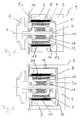
- Fig. 1 shows a canned pump 1 with an electronic commutated motor, the rotor 2 of which in a containment shell 5 rests, the one facing away from the can bottom
- An impeller 6 is attached to the end of the rotor 2.
- On the cylindrical outer surface of the can 5 is on the outside a film stand winding 4.
- the Foil stand winding 4 is radially outwards through a Stator core 3 held.
- the stator winding 4 has sensor windings, not shown, the Detect the positioning of the rotor in the containment can.
- the Stator windings 4 and the sensor windings are included the motor electronics 9 in electrical connection.
- the Motor electronics 9 takes over the electronic control of the windings in such a way that the magnetic Stator flow direction, caused by a Live winding with the magnetic Rotor flow direction, a certain angle in particular includes an average angle of 90 degrees. They don't sensor windings shown in the stator winding 4 integrated or placed on it serve as Position transmitter. The information from the rotor position sensor becomes the orderly advance of the Winding currents from one strand to the following from the motor electronics 9 used. In addition, the Information of the sensors 16, which on the Pump impeller 6 facing away from the can collar 5a are arranged to advance or control the Stator windings 4 are used.
- the engine electronics 9 is designed as a module, in particular as a cup-shaped one Module, the inner wall of the pot bottom on the The outer side of the containment shell is in contact, making a good one Heat transfer to the medium can be achieved. In addition, between the contact surfaces 13 Motor electronics 9 and the can bottom 5 a Thermal paste can be introduced.
- the engine electronics 9 also has a contact surface 14 with the stator core 3rd
- the rotor 2 is held by two bearings 10, wherein between the bearings 10 on the rotor 2 a sleeve-shaped Carrier element 11 is, which for reasons of weight is preferably made of plastic.
- the carrier element 11 holds a laminated core 12 which holds the permanent magnets 8 wearing.
- the permanent magnets 8 are either in axially extending grooves or are shape or non-positively attached to the laminated core 12.
- the electronically commutated shown in Fig. 2 Radial flux motor differs from that in FIG. 1 Motor shown in that the electronics 9 in the Motor housing is integrated, the motor housing 9 and the stator core 3 is cup-shaped.
- the Pot-shaped housing 9 includes with his cylindrical part of the stator core 3 and closes flush with the can collar 5a.
- the engine case with integrated electronics 9 lies with its Inside of the pot base and with its cylindrical Inside 14 on the outside of the pot Stand sheet metal package 3.
- the pot bottom 3a of the Stator laminated core 3 lies between the can bottom and the motor housing 9 and forms the Heat transfer resistance between engine electronics 9 and Containment shell 5.
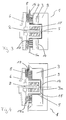
- Fig. 3 is an electronically commutated Axial flow motor shown for a canned pump 1, the stator winding on the pump impeller 6 facing side of the can collar 5a.
- the Stator winding 4 is facing away from the collar 5a Side held by the annular stator core 3.
- the module designed Motor electronics 9 with their contact surface 14.
- the rotor 2 is held by a bearing 10, the bearing 10 is in particular a plain bearing.
- the permanent magnets 8 are on the can collar 5a facing side of the pump impeller 6 arranged or poured.
- the permanent magnets 8 are approximately in radial region of the stator winding.
- the Motor electronics 9 is like the radial flux motor on the Outer wall of the containment can 5.
- the permanent magnets 8 are with their radially outward pointing end in the detection area of the sensor elements 16, the rotor position or the position of the Impeller arranged permanent magnets 8 or determine.
- the sensor elements 16 are coaxial around the Stator winding 4 are arranged and are electrically connected to the Motor electronics in connection.
- FIG. 4 Axial flux motor differs from that in FIG. 3 engine shown in that as in Fig. 2nd illustrated radial flux motor the stator core 3 as well as the motor housing with integrated motor electronics 9 is cup-shaped, again the stator winding 4 between the can collar 5a and the end face 15a of the stator core 3 lies.
- the inside of the pot Stator core 3 is completely on the Outer shell 5 on.
- the pot-shaped Stator core 3 is in turn in the pot-shaped Motor housing 9 a. Between the contact surfaces 14 of the Motor electronics 9 and the stator core 3 can be thermal paste, not shown.
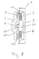
- Figure 5 describes a pump with an electronic commutated axial flux motor, in which the containment shell 5 is replaced by a flat separating body 20.
- the flat separator 20 is essentially a flat one Washer, on which the one pointing to the pump impeller 6 Side that encompasses the shaft 2 of the impeller 6 10 is attached centrally and on its other flat Side the stator winding 4 is applied, the annular stator winding 4 around a cylindrical part 21 can be arranged.
- Stator core 3 On the flat separator 20 facing end of the stator winding 4 is Stator core 3, which is for the magnetic Backflow of the stator winding 4 is used.
- the stator winding 4, the stator core 3 and additional Sensor elements 16 lie in the pot-shaped housing 9, which seals with the edge of the flat separating body 20 completes, so that the electrical or electronic Parts of the drive side protected against external influences are.
- the motor housing 9 also takes the required Motor electronics (control electronics and / or Control electronics).
Landscapes
- Engineering & Computer Science (AREA)
- Mechanical Engineering (AREA)
- General Engineering & Computer Science (AREA)
- Power Engineering (AREA)
- Microelectronics & Electronic Packaging (AREA)
- Structures Of Non-Positive Displacement Pumps (AREA)
- Windings For Motors And Generators (AREA)
- Insulation, Fastening Of Motor, Generator Windings (AREA)
- Reciprocating Pumps (AREA)
- Details And Applications Of Rotary Liquid Pumps (AREA)
Applications Claiming Priority (3)
| Application Number | Priority Date | Filing Date | Title |
|---|---|---|---|
| DE4438132A DE4438132A1 (de) | 1994-10-27 | 1994-10-27 | Spaltrohrpumpe |
| DE4438132 | 1994-10-27 | ||
| EP95114761A EP0711019B2 (fr) | 1994-10-27 | 1995-09-19 | Pompe à tube d'entrefer |
Related Parent Applications (1)
| Application Number | Title | Priority Date | Filing Date |
|---|---|---|---|
| EP95114761.0 Division | 1995-09-19 |
Publications (3)
| Publication Number | Publication Date |
|---|---|
| EP0877463A2 true EP0877463A2 (fr) | 1998-11-11 |
| EP0877463A3 EP0877463A3 (fr) | 1999-12-29 |
| EP0877463B1 EP0877463B1 (fr) | 2005-04-13 |
Family
ID=6531669
Family Applications (2)
| Application Number | Title | Priority Date | Filing Date |
|---|---|---|---|
| EP98111587A Expired - Lifetime EP0877463B1 (fr) | 1994-10-27 | 1995-09-19 | Pompe à tube d'entrefer |
| EP95114761A Expired - Lifetime EP0711019B2 (fr) | 1994-10-27 | 1995-09-19 | Pompe à tube d'entrefer |
Family Applications After (1)
| Application Number | Title | Priority Date | Filing Date |
|---|---|---|---|
| EP95114761A Expired - Lifetime EP0711019B2 (fr) | 1994-10-27 | 1995-09-19 | Pompe à tube d'entrefer |
Country Status (5)
| Country | Link |
|---|---|
| EP (2) | EP0877463B1 (fr) |
| JP (1) | JP3739838B2 (fr) |
| KR (1) | KR100332965B1 (fr) |
| DE (3) | DE4438132A1 (fr) |
| ES (1) | ES2129719T3 (fr) |
Cited By (6)
| Publication number | Priority date | Publication date | Assignee | Title |
|---|---|---|---|---|
| EP1204194A1 (fr) * | 2000-11-03 | 2002-05-08 | WILO GmbH | Boítier électronique enfichable axiallement |
| EP1126177A3 (fr) * | 2000-02-16 | 2003-12-17 | WILO GmbH | Interface électro-hydraulique |
| EP1178212A3 (fr) * | 2000-08-03 | 2005-08-31 | Claber S.P.A. | Pompe centrifugale refroidie par eau |
| EP1387087A3 (fr) * | 2002-07-29 | 2009-10-28 | Wilo Ag | Méthode pour déterminer le débit d'une pompe |
| US8360755B2 (en) | 2005-04-02 | 2013-01-29 | Pierburg Gmbh | Wet-running pump |
| DE10065796B4 (de) * | 2000-11-03 | 2020-12-24 | Wilo Se | Axial aufsteckbare Elektronik |
Families Citing this family (39)
| Publication number | Priority date | Publication date | Assignee | Title |
|---|---|---|---|---|
| DE19824345A1 (de) * | 1998-06-02 | 1999-12-09 | Wilo Gmbh | Spaltrohrpumpe mit Wicklungsträger |
| DE20007099U1 (de) | 1999-05-06 | 2000-09-28 | H. Wernert & Co. oHG, 45476 Mülheim | Kreiselpumpe |
| DE19934382A1 (de) * | 1999-07-22 | 2001-02-01 | Bosch Gmbh Robert | Flüssigkeitspumpe |
| DE19939522A1 (de) * | 1999-08-20 | 2001-02-22 | Wilo Gmbh | Elektromotorisch angetriebene Kreiselpumpe mit außenliegendem Rotor |
| DE19940457A1 (de) * | 1999-08-25 | 2001-03-01 | Wilo Gmbh | Axialflußmotor |
| DE19956380C1 (de) * | 1999-11-24 | 2001-01-04 | Bosch Gmbh Robert | Flüssigkeitspumpe mit einem Motorgehäuse und Verfahren zur Herstellung eines Motorgehäuses |
| DE10025190A1 (de) * | 2000-05-20 | 2001-12-06 | Wilo Gmbh | Spaltrohrmotor mit Folienspaltrohr |
| DE10051403A1 (de) | 2000-10-17 | 2002-06-13 | Minebea Co Ltd | Rotorbaugruppe für einen Elektromotor und Innenläufer-Elektromotor |
| JP2002205010A (ja) * | 2001-01-09 | 2002-07-23 | Citizen Watch Co Ltd | ブラシレス振動モータユニット |
| GB0105722D0 (en) * | 2001-03-08 | 2001-04-25 | Lucas Industries Ltd | Improvements in electric motor driven hydraulic pumps |
| DE10144653B4 (de) * | 2001-09-11 | 2006-05-11 | Ate Antriebstechnik Und Entwicklungs Gmbh | Permanent erregte elektromechanische Maschine für den Betrieb in Flüssigkeiten und Gasen |
| DE10157194A1 (de) * | 2001-11-23 | 2003-06-05 | Wilo Gmbh | Spaltrohrpumpe mit Sensor |
| US6863504B2 (en) | 2002-02-28 | 2005-03-08 | Standex International Corp. | Fluid pump relief valve |
| US6814549B2 (en) | 2002-02-28 | 2004-11-09 | Standex International Corp. | Liner for fluid pump motor |
| ATE313013T1 (de) * | 2002-02-28 | 2005-12-15 | Standex Int Corp | Motorpumpe |
| US6847140B2 (en) | 2002-02-28 | 2005-01-25 | Standex International Corp. | Fluid barrier for motor rotor |
| US6884043B2 (en) | 2002-02-28 | 2005-04-26 | Standex International Corp. | Fluid circulation path for motor pump |
| US6837688B2 (en) | 2002-02-28 | 2005-01-04 | Standex International Corp. | Overheat protection for fluid pump |
| DE10307708A1 (de) † | 2003-02-24 | 2004-09-09 | Lenze Drive Systems Gmbh | Verfahren zur Temperaturüberwachung eines Elektromotors |
| DE10318702A1 (de) * | 2003-04-24 | 2005-03-03 | Wilo Ag | Verfahren und Vorrichtung zur Herstellung einer eisenlosen Stator-Wicklung |
| DE10352487A1 (de) * | 2003-07-22 | 2005-02-10 | BSH Bosch und Siemens Hausgeräte GmbH | Pumpe mit integriertem Motor |
| DE102004003400B4 (de) * | 2004-01-23 | 2012-08-23 | Ksb Aktiengesellschaft | Kreiselpumpenaggregat |
| DE102004042664A1 (de) * | 2004-09-01 | 2006-03-02 | Wilo Ag | Verfahren zur berührungslosen Drehzahlmessung für Elektromotoren |
| DE102004046950B4 (de) * | 2004-09-28 | 2021-10-28 | Volkswagen Ag | Druckversorgungseinrichtung und Verfahren zur Steuerung einer Druckversorgungseinrichtung |
| DE102005057661A1 (de) * | 2005-12-01 | 2007-06-06 | Wilo Ag | Kreiselpumpe mit Spalttopf |
| EP2031737A1 (fr) * | 2007-08-30 | 2009-03-04 | Alcatel Lucent | Moteur électrique sans balai et pompe électrique |
| ES2402667T5 (es) * | 2008-04-19 | 2016-06-28 | Grundfos Management A/S | Componente de carcasa de estator para un motor encapsulado hermético |
| EP2466731B1 (fr) * | 2010-12-15 | 2013-06-12 | Infranor Holding S.A. | Moteur synchrone doté d'aimants permanents |
| DE102011075097A1 (de) * | 2011-05-02 | 2012-11-08 | Krones Aktiengesellschaft | Vorrichtung zum Bewegen eines Fluids |
| DE202011051526U1 (de) | 2011-10-05 | 2011-11-03 | Wita-Wilhelm Taake Gmbh | Nassläuferpumpe mit modularer Bauweise |
| DE102012019423B3 (de) * | 2012-10-02 | 2013-12-05 | Dickow-Pumpen Kg | Doppelspalttopf |
| DE202013101587U1 (de) | 2013-04-15 | 2013-04-25 | Wita-Wilhelm Taake Gmbh | Statorpaket für eine Spaltrohrpumpe |
| DE102013008795B3 (de) | 2013-05-24 | 2014-08-21 | Ksb Aktiengesellschaft | Pumpenanordnung |
| CN104378727A (zh) * | 2014-11-11 | 2015-02-25 | 苏州立人听力器材有限公司 | 一种固化更均匀的耳模夹持装置 |
| DE102015000704B3 (de) | 2015-01-20 | 2016-01-21 | Sartorius Stedim Biotech Gmbh | Mischvorrichtung mit einem Rührelement, eine Antriebsvorrichtung zum Antreiben eines Rührelements in einer Mischvorrichtung, ein Mischvorrichtungssystem und ein Verfahren zum Antreiben eines Rührelements in einer Mischvorrichtung |
| DE102015101487B4 (de) * | 2015-02-02 | 2023-07-13 | Aesculap Ag | Chirurgiemotor |
| WO2022069021A1 (fr) * | 2020-09-29 | 2022-04-07 | Pierburg Gmbh | Moteur électrique pour l'entraînement d'une unité |
| DE102021111682A1 (de) | 2021-05-05 | 2022-11-10 | Nidec Gpm Gmbh | Kreiselpumpe mit nasslaufendem Elektromotor |
| KR20230086165A (ko) * | 2021-12-08 | 2023-06-15 | 현대자동차주식회사 | 전동식 워터 펌프 |
Family Cites Families (41)
| Publication number | Priority date | Publication date | Assignee | Title |
|---|---|---|---|---|
| DE1052541B (de) * | 1957-02-12 | 1959-03-12 | Ritz Motorenbau K G | Gekapselter Induktionsmotor, insbesondere Unterwassermotor fuer Pumpenantriebe |
| US2961555A (en) * | 1957-06-07 | 1960-11-22 | Gen Electric | Encapsulated stator and method of making the same |
| DE1096476B (de) * | 1959-03-16 | 1961-01-05 | Klein Schanzlin & Becker Ag | Elektrische Antriebsmaschine, insbesondere zum Antrieb von Kreiselpumpenaggregaten |
| DE1116796B (de) * | 1960-02-02 | 1961-11-09 | Klein Schanzlin & Becker Ag | Elektrische Antriebsmaschine mit mit Giessharz umgossenem Stator, insbesondere zum Antrieb von Kreiselpumpenaggregaten |
| FR1296666A (fr) * | 1961-05-09 | 1962-06-22 | Emile Salmson Fils De | Accélérateur de circulation ou pompe centrifuge sans presse-étoupe, entraîné par moteur électrique à circuits imprimés |
| DE1895968U (de) * | 1964-04-15 | 1964-07-02 | Hans Dr Ing Moser | Umwalzpumpe. |
| GB1187866A (en) * | 1967-11-16 | 1970-04-15 | Sealed Motor Const Co Ltd | Improvements in and relating to Electric Motorised Centrifugal Pumps. |
| DE1638272B2 (de) * | 1968-03-02 | 1975-05-28 | Siemens Ag, 1000 Berlin Und 8000 Muenchen | Pumpe mit Spaltrohrmotor |
| DE2251928A1 (de) * | 1972-10-23 | 1974-05-09 | Halberg Maschbau Gmbh & Co | Spaltrohrmotorpumpe zur foerderung von zum erstarren neigenden medien |
| GB1414949A (en) * | 1974-02-05 | 1975-11-19 | Laing Ingeborg | Rotary magnetic machines |
| US3932069A (en) * | 1974-12-19 | 1976-01-13 | Ford Motor Company | Variable reluctance motor pump |
| JPS5797348A (en) * | 1980-12-10 | 1982-06-17 | Matsushita Electric Ind Co Ltd | Manufacture of coreless armature |
| US4404483A (en) * | 1981-02-26 | 1983-09-13 | Taco, Inc. | Method of fabricating a wet-rotor circulator and circulator produced thereby |
| JPS58180787A (ja) * | 1982-04-16 | 1983-10-22 | Matsushita Electric Ind Co Ltd | ギヤ−ポンプ |
| JPS58190266A (ja) * | 1982-04-28 | 1983-11-07 | Shibaura Eng Works Co Ltd | ブラシレスモ−タ |
| JPS58222745A (ja) * | 1982-06-16 | 1983-12-24 | Shibaura Eng Works Co Ltd | ブラシレスモ−タ |
| EP0105687A1 (fr) * | 1982-09-27 | 1984-04-18 | Milton Roy Co. | Pompe électrique à commutation électronique |
| DE3331002A1 (de) * | 1983-08-27 | 1985-03-14 | Robert Bosch Gmbh, 7000 Stuttgart | Elektrische maschine |
| DE3526166C2 (de) * | 1984-07-23 | 1996-05-02 | Asahi Chemical Ind | Bürstenloser Elektromotor und Verfahren zum Herstellen einer Spuleneinheit für diesen |
| US4679313A (en) † | 1985-03-08 | 1987-07-14 | Kollmorgen Technologies Corporation | Method of making a servo motor with high energy product magnets |
| DE3536092A1 (de) * | 1985-10-09 | 1987-04-16 | Ngk Insulators Ltd | Magnetkupplungs-zentrifugalpumpe |
| US4709180A (en) * | 1985-11-20 | 1987-11-24 | The Garrett Corporation | Toothless stator construction for electrical machines |
| CH670017A5 (en) * | 1986-03-03 | 1989-04-28 | Papst Motoren Gmbh & Co Kg | Miniature permanent magnet electric motor - has narrow cylindrical air-gap and integral outer housing and stator of sintered metal |
| US4883981A (en) * | 1986-06-04 | 1989-11-28 | Gerfast Sten R | Dynamoelectric machine having ironless stator coil |
| DE3622231A1 (de) * | 1986-07-02 | 1988-01-07 | Bosch Gmbh Robert | Permanentmagnetrotor fuer elektrische maschinen |
| DE8624505U1 (de) * | 1986-09-12 | 1987-07-09 | Siemens AG, 1000 Berlin und 8000 München | Leiterplatte |
| GB2202685A (en) * | 1987-03-23 | 1988-09-28 | Johnson Electric Ind Mfg | Printed circuit stator for a brushless D.C. electric motor |
| US4843269A (en) * | 1987-10-01 | 1989-06-27 | Adalet/Scott Fetzer Company | Large air gap motor |
| US4876492A (en) * | 1988-02-26 | 1989-10-24 | General Electric Company | Electronically commutated motor driven apparatus including an impeller in a housing driven by a stator on the housing |
| DE3820857C2 (de) * | 1988-06-04 | 1993-12-02 | Licentia Gmbh | Elektromotor mit einem Außenläufer und einem mit diesem verbundenem Lüfterrad |
| DE3821030A1 (de) * | 1988-06-22 | 1989-12-28 | Oplaender Wilo Werk Gmbh | Spaltrohrpumpe |
| US4975607A (en) * | 1988-07-11 | 1990-12-04 | Kabushiki Kaisha Sankyo Seiki Seisakusho | Frequency generator with superimposed generation coil |
| DE3916791C3 (de) * | 1988-10-28 | 1998-09-17 | Valeo Sistemi Termici S P A | Gebläse-Einbausatz einer Kraftwagenheizung |
| ES2065976T3 (es) * | 1988-12-18 | 1995-03-01 | Buck Chem Tech Werke | Motor sincronico con conmutacion electronica. |
| DE3843477A1 (de) † | 1988-12-23 | 1990-06-28 | Oplaender Wilo Werk Gmbh | Spaltrohr-elektromotor |
| ES2066039T3 (es) * | 1989-06-05 | 1995-03-01 | Ebara Corp | Bomba de iman. |
| US5197180A (en) * | 1991-09-13 | 1993-03-30 | Faraday Energy Foundation | Method for making an electric motor winding |
| DE9200510U1 (de) * | 1992-01-17 | 1992-11-12 | Siemens Ag, 8000 Muenchen | Naßläuferpumpe |
| DE4303629A1 (de) * | 1993-02-09 | 1994-08-18 | Junkalor Gmbh | Übertemperatur- und Anlaufsicherung in Pumpen mit Permanentmagnet-Kupplungen |
| DE4309382A1 (de) * | 1993-03-23 | 1994-09-29 | Bosch Gmbh Robert | Elektronisch kommutierter Elektromotor |
| DE9315098U1 (de) * | 1993-10-05 | 1994-03-03 | Unterreitmaier, Martin, 80339 München | Bausatz für elektronische Drehzahlregelung zu Rems Tigersäge |
-
1994
- 1994-10-27 DE DE4438132A patent/DE4438132A1/de not_active Ceased
-
1995
- 1995-09-19 EP EP98111587A patent/EP0877463B1/fr not_active Expired - Lifetime
- 1995-09-19 DE DE59510999T patent/DE59510999D1/de not_active Expired - Lifetime
- 1995-09-19 ES ES95114761T patent/ES2129719T3/es not_active Expired - Lifetime
- 1995-09-19 EP EP95114761A patent/EP0711019B2/fr not_active Expired - Lifetime
- 1995-09-19 DE DE59505502T patent/DE59505502D1/de not_active Expired - Lifetime
- 1995-10-19 KR KR1019950036181A patent/KR100332965B1/ko not_active Expired - Fee Related
- 1995-10-26 JP JP27908495A patent/JP3739838B2/ja not_active Expired - Fee Related
Cited By (7)
| Publication number | Priority date | Publication date | Assignee | Title |
|---|---|---|---|---|
| EP1126177A3 (fr) * | 2000-02-16 | 2003-12-17 | WILO GmbH | Interface électro-hydraulique |
| EP1178212A3 (fr) * | 2000-08-03 | 2005-08-31 | Claber S.P.A. | Pompe centrifugale refroidie par eau |
| EP1204194A1 (fr) * | 2000-11-03 | 2002-05-08 | WILO GmbH | Boítier électronique enfichable axiallement |
| DE10065796B4 (de) * | 2000-11-03 | 2020-12-24 | Wilo Se | Axial aufsteckbare Elektronik |
| DE10107248B4 (de) | 2000-11-03 | 2021-09-23 | Wilo Se | In vier Positionen aufsteckbare Motorelektronik |
| EP1387087A3 (fr) * | 2002-07-29 | 2009-10-28 | Wilo Ag | Méthode pour déterminer le débit d'une pompe |
| US8360755B2 (en) | 2005-04-02 | 2013-01-29 | Pierburg Gmbh | Wet-running pump |
Also Published As
| Publication number | Publication date |
|---|---|
| KR100332965B1 (ko) | 2002-11-20 |
| JPH08214483A (ja) | 1996-08-20 |
| EP0877463A3 (fr) | 1999-12-29 |
| EP0711019B1 (fr) | 1999-03-31 |
| EP0711019B2 (fr) | 2003-03-26 |
| DE59505502D1 (de) | 1999-05-06 |
| DE59510999D1 (de) | 2005-05-19 |
| DE4438132A1 (de) | 1996-05-02 |
| ES2129719T3 (es) | 1999-06-16 |
| EP0711019A1 (fr) | 1996-05-08 |
| KR960014673A (ko) | 1996-05-22 |
| EP0877463B1 (fr) | 2005-04-13 |
| JP3739838B2 (ja) | 2006-01-25 |
Similar Documents
| Publication | Publication Date | Title |
|---|---|---|
| EP0877463A2 (fr) | Pompe à tube d'entrefer | |
| EP0963029B1 (fr) | Pompe à tube d'entrefer avec support d'enroulement | |
| EP1422809B1 (fr) | Moteur électrique pour entraîner une pompe | |
| EP2547910B1 (fr) | Ventilateur à moteur à rotor extérieur avec carter de paliers et logement pour l'électronique de contrôle intégrés | |
| EP1149245B1 (fr) | Pompe a liquide presentant un boitier moteur et procede de realisation d'un boitier moteur | |
| DE69030954T2 (de) | Implantierbare Zentrifugalpumpe zur Herzunterstützung mit Radialantrieb | |
| US7394174B2 (en) | Brushless D.C. motor | |
| EP2567447B1 (fr) | Pompe dotée d'un moteur à courant continu intégré à commutation électronique | |
| EP1689065B1 (fr) | Stator pour machine électrique et sa méthode de fabrication | |
| EP1256722B1 (fr) | Pompe centrifugale | |
| DE4411960C2 (de) | Von einem elektronisch kommutierten Elektromotor angetriebene Flüssigkeitspumpe | |
| EP1531272A2 (fr) | Ventilateur avec capteur | |
| DE102014201490A1 (de) | Kreiselpumpenmotor | |
| DE7823664U1 (de) | Kompakter ventilator | |
| EP1866546B1 (fr) | Pompe a rotor noye | |
| EP0713282B1 (fr) | Moteur à manchon d'entrefer | |
| EP0190297B1 (fr) | Moteur a commande directe axialement compact | |
| EP1812714B1 (fr) | Ensemble comprenant un ventilateur et une pompe | |
| WO2013037449A2 (fr) | Groupe électro-pompe | |
| EP3391509B1 (fr) | Moteur électrique | |
| DE4403820C2 (de) | Kommutatormotor | |
| WO2024013307A1 (fr) | Moteur électrique, notamment moteur de ventilateur de radiateur | |
| WO2013107807A2 (fr) | Pompe a rotor noyé | |
| EP1797330B1 (fr) | Dispositif de transport de fluides | |
| DE3502284A1 (de) | Kollektorloser gleichstrommotor |
Legal Events
| Date | Code | Title | Description |
|---|---|---|---|
| PUAI | Public reference made under article 153(3) epc to a published international application that has entered the european phase |
Free format text: ORIGINAL CODE: 0009012 |
|
| 17P | Request for examination filed |
Effective date: 19980624 |
|
| AC | Divisional application: reference to earlier application |
Ref document number: 711019 Country of ref document: EP |
|
| AK | Designated contracting states |
Kind code of ref document: A2 Designated state(s): CH DE ES FR GB IT LI NL |
|
| PUAL | Search report despatched |
Free format text: ORIGINAL CODE: 0009013 |
|
| AK | Designated contracting states |
Kind code of ref document: A3 Designated state(s): CH DE ES FR GB IT LI NL |
|
| 17Q | First examination report despatched |
Effective date: 20010615 |
|
| RAP1 | Party data changed (applicant data changed or rights of an application transferred) |
Owner name: WILO AG |
|
| GRAP | Despatch of communication of intention to grant a patent |
Free format text: ORIGINAL CODE: EPIDOSNIGR1 |
|
| GRAS | Grant fee paid |
Free format text: ORIGINAL CODE: EPIDOSNIGR3 |
|
| GRAA | (expected) grant |
Free format text: ORIGINAL CODE: 0009210 |
|
| AC | Divisional application: reference to earlier application |
Ref document number: 0711019 Country of ref document: EP Kind code of ref document: P |
|
| AK | Designated contracting states |
Kind code of ref document: B1 Designated state(s): CH DE ES FR GB IT LI NL |
|
| REG | Reference to a national code |
Ref country code: GB Ref legal event code: FG4D Free format text: NOT ENGLISH |
|
| REG | Reference to a national code |
Ref country code: CH Ref legal event code: EP |
|
| REF | Corresponds to: |
Ref document number: 59510999 Country of ref document: DE Date of ref document: 20050519 Kind code of ref document: P |
|
| REG | Reference to a national code |
Ref country code: CH Ref legal event code: NV Representative=s name: SCHMAUDER & PARTNER AG PATENTANWALTSBUERO |
|
| GBT | Gb: translation of ep patent filed (gb section 77(6)(a)/1977) |
Effective date: 20050525 |
|
| PG25 | Lapsed in a contracting state [announced via postgrant information from national office to epo] |
Ref country code: ES Free format text: LAPSE BECAUSE OF FAILURE TO SUBMIT A TRANSLATION OF THE DESCRIPTION OR TO PAY THE FEE WITHIN THE PRESCRIBED TIME-LIMIT Effective date: 20050724 |
|
| PLBE | No opposition filed within time limit |
Free format text: ORIGINAL CODE: 0009261 |
|
| STAA | Information on the status of an ep patent application or granted ep patent |
Free format text: STATUS: NO OPPOSITION FILED WITHIN TIME LIMIT |
|
| ET | Fr: translation filed | ||
| 26N | No opposition filed |
Effective date: 20060116 |
|
| PGFP | Annual fee paid to national office [announced via postgrant information from national office to epo] |
Ref country code: CH Payment date: 20070913 Year of fee payment: 13 |
|
| PGFP | Annual fee paid to national office [announced via postgrant information from national office to epo] |
Ref country code: GB Payment date: 20070919 Year of fee payment: 13 |
|
| PGFP | Annual fee paid to national office [announced via postgrant information from national office to epo] |
Ref country code: NL Payment date: 20070903 Year of fee payment: 13 Ref country code: IT Payment date: 20070926 Year of fee payment: 13 |
|
| PGFP | Annual fee paid to national office [announced via postgrant information from national office to epo] |
Ref country code: FR Payment date: 20070914 Year of fee payment: 13 |
|
| REG | Reference to a national code |
Ref country code: CH Ref legal event code: PL |
|
| GBPC | Gb: european patent ceased through non-payment of renewal fee |
Effective date: 20080919 |
|
| PG25 | Lapsed in a contracting state [announced via postgrant information from national office to epo] |
Ref country code: NL Free format text: LAPSE BECAUSE OF NON-PAYMENT OF DUE FEES Effective date: 20090401 |
|
| NLV4 | Nl: lapsed or anulled due to non-payment of the annual fee |
Effective date: 20090401 |
|
| REG | Reference to a national code |
Ref country code: FR Ref legal event code: ST Effective date: 20090529 |
|
| PG25 | Lapsed in a contracting state [announced via postgrant information from national office to epo] |
Ref country code: IT Free format text: LAPSE BECAUSE OF NON-PAYMENT OF DUE FEES Effective date: 20080919 |
|
| PG25 | Lapsed in a contracting state [announced via postgrant information from national office to epo] |
Ref country code: LI Free format text: LAPSE BECAUSE OF NON-PAYMENT OF DUE FEES Effective date: 20080930 Ref country code: FR Free format text: LAPSE BECAUSE OF NON-PAYMENT OF DUE FEES Effective date: 20080930 Ref country code: CH Free format text: LAPSE BECAUSE OF NON-PAYMENT OF DUE FEES Effective date: 20080930 |
|
| PG25 | Lapsed in a contracting state [announced via postgrant information from national office to epo] |
Ref country code: GB Free format text: LAPSE BECAUSE OF NON-PAYMENT OF DUE FEES Effective date: 20080919 |
|
| PGFP | Annual fee paid to national office [announced via postgrant information from national office to epo] |
Ref country code: DE Payment date: 20090917 Year of fee payment: 15 |
|
| REG | Reference to a national code |
Ref country code: DE Ref legal event code: R119 Ref document number: 59510999 Country of ref document: DE Effective date: 20110401 |
|
| PG25 | Lapsed in a contracting state [announced via postgrant information from national office to epo] |
Ref country code: DE Free format text: LAPSE BECAUSE OF NON-PAYMENT OF DUE FEES Effective date: 20110401 |