EP0877488A1 - Procédé pour mesurer l'angle de rotation d'un arbre rotatif, en particulier d'un commutateur rotatif, et dispositif pour la mise en oeuvre du procédé - Google Patents
Procédé pour mesurer l'angle de rotation d'un arbre rotatif, en particulier d'un commutateur rotatif, et dispositif pour la mise en oeuvre du procédé Download PDFInfo
- Publication number
- EP0877488A1 EP0877488A1 EP98106206A EP98106206A EP0877488A1 EP 0877488 A1 EP0877488 A1 EP 0877488A1 EP 98106206 A EP98106206 A EP 98106206A EP 98106206 A EP98106206 A EP 98106206A EP 0877488 A1 EP0877488 A1 EP 0877488A1
- Authority
- EP
- European Patent Office
- Prior art keywords
- angle
- value
- quadrant
- curve
- values
- Prior art date
- Legal status (The legal status is an assumption and is not a legal conclusion. Google has not performed a legal analysis and makes no representation as to the accuracy of the status listed.)
- Granted
Links
Images



Classifications
-
- H—ELECTRICITY
- H03—ELECTRONIC CIRCUITRY
- H03M—CODING; DECODING; CODE CONVERSION IN GENERAL
- H03M1/00—Analogue/digital conversion; Digital/analogue conversion
- H03M1/12—Analogue/digital converters
- H03M1/22—Analogue/digital converters pattern-reading type
- H03M1/24—Analogue/digital converters pattern-reading type using relatively movable reader and disc or strip
- H03M1/28—Analogue/digital converters pattern-reading type using relatively movable reader and disc or strip with non-weighted coding
- H03M1/30—Analogue/digital converters pattern-reading type using relatively movable reader and disc or strip with non-weighted coding incremental
- H03M1/303—Circuits or methods for processing the quadrature signals
- H03M1/306—Circuits or methods for processing the quadrature signals for waveshaping
-
- G—PHYSICS
- G01—MEASURING; TESTING
- G01D—MEASURING NOT SPECIALLY ADAPTED FOR A SPECIFIC VARIABLE; ARRANGEMENTS FOR MEASURING TWO OR MORE VARIABLES NOT COVERED IN A SINGLE OTHER SUBCLASS; TARIFF METERING APPARATUS; MEASURING OR TESTING NOT OTHERWISE PROVIDED FOR
- G01D5/00—Mechanical means for transferring the output of a sensing member; Means for converting the output of a sensing member to another variable where the form or nature of the sensing member does not constrain the means for converting; Transducers not specially adapted for a specific variable
- G01D5/12—Mechanical means for transferring the output of a sensing member; Means for converting the output of a sensing member to another variable where the form or nature of the sensing member does not constrain the means for converting; Transducers not specially adapted for a specific variable using electric or magnetic means
- G01D5/14—Mechanical means for transferring the output of a sensing member; Means for converting the output of a sensing member to another variable where the form or nature of the sensing member does not constrain the means for converting; Transducers not specially adapted for a specific variable using electric or magnetic means influencing the magnitude of a current or voltage
- G01D5/142—Mechanical means for transferring the output of a sensing member; Means for converting the output of a sensing member to another variable where the form or nature of the sensing member does not constrain the means for converting; Transducers not specially adapted for a specific variable using electric or magnetic means influencing the magnitude of a current or voltage using Hall-effect devices
- G01D5/145—Mechanical means for transferring the output of a sensing member; Means for converting the output of a sensing member to another variable where the form or nature of the sensing member does not constrain the means for converting; Transducers not specially adapted for a specific variable using electric or magnetic means influencing the magnitude of a current or voltage using Hall-effect devices influenced by the relative movement between the Hall device and magnetic fields
Definitions
- the invention relates to a method for measuring the angle of rotation of a rotatable shaft, in which two sinusoidal, phase-shifted signals are generated and the angle of rotation is inferred from the measured values of the signals, the sinusoidal signals being normalized before the first measurement and a device for Execution of the procedure.
- the sinusoidal signals are subject to fluctuations in the amplitude which are caused, for example, by aging or by the temperature response of the components used. For this reason, in known methods, which infer the measured angle of rotation from the measured values via arc sine and arc cosine functions, the normalization is also repeated during the ongoing measurements. This is done, for example, by measuring an extreme value for one signal when a zero crossing is determined for the other signal.
- the object of the invention is to provide a method and an apparatus for executing the method, which only require simple calculations. This object is achieved in that the signals which are larger than the normalized maximum or smaller than the normalized minimum value are limited to the maximum or minimum value. Furthermore, the quadrant in which the sought angle is located is determined from the value of the two measured signals. Depending on the sign of the respective curve slope, the sign of the measured signal value is changed or maintained.
- the sign of the associated signal value can be retained if the respective curve has a positive slope and the sign of the signal value can be changed if the respective curve has a negative slope, or the sign of the respective signal values can be changed if the respective curve has a positive slope and if the respective curve has a negative slope, the sign of the signal value is retained (second alternative).
- the signal values obtained in this way are added together and a first sum S is obtained.
- This method has the advantage of being based on normalizations during measurements can be dispensed with.
- the difference angle ⁇ can also be read graphically on a third curve. If that with a negative slope of the respective sinusoidal curve
- the third curve shows the sign of the measured value at the beginning of each quadrant half the negative value of the amplitude difference between the normalized maximum and minimum amplitude, in which In the middle of the quadrant the value 0 and at the end of the respective quadrant half the positive value of the amplitude difference between the normalized Maximum and minimum amplitude. Is the curve within a quadrant each straight, the read values agree with the Equation 1 obtained. It is more complex, but more precise third curve, if you sum the sum of the values for a number of angles assigns respective sine and cosine values to their respective angles The sign of a falling signal curve was changed.
- a fourth curve ranging from 0 to four times the amplitude difference AD extends between the normalized maximum and minimum amplitude, assigns a certain angle to each angle within the four quadrants Value too, so that with the determined value the angle in the fourth curve can be read. To do this, you must add the calculated first sum of the two measured values in each quadrant each as many values of the Amplitude difference AD can be added as needed to the third curve of its position between the negative half of the amplitude difference AD and half the value of the amplitude difference AD in each quadrant to the corresponding position in the respective quadrant to postpone.
- a device for performing the method has a device that generates a sinusoidal signal by rotation and which is connected to the shaft whose angle of rotation is to be determined, especially a rotatable switch. Furthermore, the device has two Sensors arranged at the same distance from the axis of rotation of the shaft are that they detect the signal emitted by the device can, the sensors being arranged so that those picked up by them Signals are phase-shifted by 90 °. Finally, the Device an evaluation device based on the recorded signals calculated the angle using the method according to the invention.
- the Device that generates a sinusoidal signal advantageously exists from a magnet that is rotatably mounted around its perpendicular bisector.
- the Sensors are then advantageously designed as Hall sensors or coils. A particularly simple circuit structure can be used realized by self-adjusting Hall sensors.
- FIG. 1 shows a rotatable switch in which a shaft W with a diametrically magnetized disk M is rotatably mounted via a handle H.
- the diametrically magnetized disc M generates voltages in the Hall sensors SE, from whose values the angle of rotation of the shaft W can be calculated using the method according to the invention.
- Two coils SP1, SP2 are arranged so that they generate a torque when the current is applied to them in cooperation with the diametrically magnetized disc M, which the operator of the switch can perceive via the handle H.
- FIG. 2 shows the voltages that two Hall sensors deliver, for example, during a rotation of a diametrically magnetized disc by 360 °, the is connected to the shaft whose angle of rotation is to be determined.
- This Tensions are increased and offset. This happens advantageously already in those available today Hall sensors.
- the Hall sensors advantageously have a compensation circuit, minimize the fluctuations of the offset voltage OF.
- the signals are advantageously digitized using an A / D converter and in an evaluation unit, which consists of a microcontroller or microprocessor can exist, edited.
- the amplitude of the normalized voltage is advantageously used the minimum occurring amplitude of the signals for sine 90 ° or cosine 0 °.
- the resulting advantages will be explained later in particular of Figure 8 are explained in more detail.
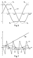
- FIG. 4 shows the changes in the signs of the values WA, WB of the sine curve A and the cosine curve B in the four quadrants I to IV.
- the sine curve A has a negative slope in the second and third quadrants II, III.
- the sign of a measured function value WA is therefore changed in these quadrants.
- the cosine curve B has a negative slope in the first and second quadrants I, II, therefore a sign of a measured function value WB is changed in the first and second quadrants I, II.
- the first sum is formed from the sum of the adapted function values WAV, WBV of the respective function values WA, WB, which are measured at an angle ⁇ to be determined.
- the first sum corresponds to the angle difference ⁇ between the center of the respective quadrant (45 °, 135 °, 225 °, 315 °) and the measured angle ⁇ , the value of the amplitude difference AD between the standardized maximum amplitude (+1) and the standardized minimum amplitude (-1) corresponds to a value of 90 °.
- the angle ⁇ which is between 0 ° and the center of the quadrant, in which the searched angle ⁇ is to be added to the angle ⁇ .
- the third curve K is also shown in FIG.
- the curve K begins at -1 at the beginning of each quadrant, has in the middle of each quadrant the value 0 and increases to the end of the respective quadrant the value 1.
- the third curve K is either between the beginning and the End of a quadrant is a distance, or else it is divided by the sum receive the respective sine and cosine values of the corresponding angles, the signs of the respective function values WA, WB then changed if the respective function has a negative slope.
- the fourth curve K 4 shown in FIG. 5 is obtained, those from 0 at the beginning of the first quadrant to 8 (four times the value of the Amplitude difference AD between the normalized maximum (plus 1) and minimum (-1) amplitude) is sufficient.
- the error F 1 is still in Degree shown, which arises from that for the determination of the sought Angle ⁇ , equation 1 is used instead of reading the Angle on a third curve K, by adding the angles corresponding to the Sine and cosine values, whose signs have been adjusted accordingly was received.
- system-related error F1 of up to +/- 2 ° compared to the actual one Angle when the measured sine and cosine curves match the normalized Values.
- FIG. 6 shows the curves of two sinusoidal signals A1, B1 after normalization, the amplitude of which before the limitation had 1.2 times the value of the normalized signal, as shown by the dotted curve pieces A 0 B 0 .
- FIG. 7 shows the two signals A1, B1 from FIG. 6 and the curve K6, which is obtained by adding for the curves A1, B1 with an adapted sign and providing an offset in each quadrant such that the curve is continuous is.
- the offset has the following values: In the first quadrant +0.5 AD In the second quadrant +1.5 AD In the third quadrant +2.5 AD In the fourth quadrant +3.5 AD.
- a diametrically magnetized disc M is shown, which with the Rotary shaft W is connected.
- Two sensors SE are at the same radial distance from the rotary shaft W and the disc M offset by 90 °.
- the rotation creates sinusoidal signals between the Hall sensors SE are 90 ° out of phase.
Landscapes
- Engineering & Computer Science (AREA)
- Physics & Mathematics (AREA)
- General Physics & Mathematics (AREA)
- Signal Processing (AREA)
- Theoretical Computer Science (AREA)
- Transmission And Conversion Of Sensor Element Output (AREA)
- Measurement Of Length, Angles, Or The Like Using Electric Or Magnetic Means (AREA)
Applications Claiming Priority (2)
| Application Number | Priority Date | Filing Date | Title |
|---|---|---|---|
| DE19719564A DE19719564A1 (de) | 1997-05-09 | 1997-05-09 | Verfahren zum Messen des Drehwinkels einer drehbaren Welle, insbesondere eines drehbaren Schalters und Vorrichtung zur Ausführung des Verfahrens |
| DE19719564 | 1997-05-09 |
Publications (2)
| Publication Number | Publication Date |
|---|---|
| EP0877488A1 true EP0877488A1 (fr) | 1998-11-11 |
| EP0877488B1 EP0877488B1 (fr) | 2002-09-04 |
Family
ID=7829068
Family Applications (1)
| Application Number | Title | Priority Date | Filing Date |
|---|---|---|---|
| EP98106206A Expired - Lifetime EP0877488B1 (fr) | 1997-05-09 | 1998-04-04 | Procédé pour mesurer l'angle de rotation d'un arbre rotatif, en particulier d'un commutateur rotatif, et dispositif pour la mise en oeuvre du procédé |
Country Status (3)
| Country | Link |
|---|---|
| US (1) | US6087829A (fr) |
| EP (1) | EP0877488B1 (fr) |
| DE (2) | DE19719564A1 (fr) |
Cited By (3)
| Publication number | Priority date | Publication date | Assignee | Title |
|---|---|---|---|---|
| GB2392249A (en) * | 2000-01-27 | 2004-02-25 | Goodrich Avionics Systems Inc | Encoder apparatus and controller |
| EP1061342A3 (fr) * | 1999-06-15 | 2005-08-17 | Hella KGaA Hueck & Co. | Capteur de position pour un véhicule |
| WO2013127962A1 (fr) * | 2012-02-29 | 2013-09-06 | Zentrum Mikroelektronik Dresden Ag | Dispositif et procédé pour la détermination de position absolue redondante d'un corps mobile |
Families Citing this family (22)
| Publication number | Priority date | Publication date | Assignee | Title |
|---|---|---|---|---|
| JP2001174289A (ja) * | 1999-12-17 | 2001-06-29 | Alps Electric Co Ltd | 回転角検出装置 |
| US6556005B1 (en) * | 2000-01-27 | 2003-04-29 | Goodrich Avionics Systems, Inc. | Magnetic encoder apparatus capable of resolving axial and rotational displacements |
| US6566860B1 (en) * | 2000-09-14 | 2003-05-20 | Delphi Technologies, Inc. | Method for temperature compensation for the output of an angular position sensor |
| DE10114258A1 (de) * | 2001-03-22 | 2002-09-26 | Ivo Gmbh & Co | Winkelmessvorrichtung zur Erfassung der genauen absoluten Position einer Geberwelle |
| DE10224288A1 (de) * | 2002-05-31 | 2003-12-11 | Zf Lenksysteme Gmbh | Vorrichtung zur Messung eines Drehwinkels |
| US20040040800A1 (en) * | 2002-07-31 | 2004-03-04 | George Anastas | System and method for providing passive haptic feedback |
| DE10301848B4 (de) | 2003-01-09 | 2014-10-09 | Anton Rodi | Messeinrichtung zur Erfassung von Größen, insbesondere von Winkeln oder Wegstrecken |
| EP1631893A2 (fr) * | 2003-05-30 | 2006-03-08 | Immersion Corporation | Systeme et procede de retroaction haptique faible puissance |
| US7522152B2 (en) * | 2004-05-27 | 2009-04-21 | Immersion Corporation | Products and processes for providing haptic feedback in resistive interface devices |
| US7198137B2 (en) * | 2004-07-29 | 2007-04-03 | Immersion Corporation | Systems and methods for providing haptic feedback with position sensing |
| US8441433B2 (en) * | 2004-08-11 | 2013-05-14 | Immersion Corporation | Systems and methods for providing friction in a haptic feedback device |
| US9495009B2 (en) * | 2004-08-20 | 2016-11-15 | Immersion Corporation | Systems and methods for providing haptic effects |
| US8013847B2 (en) * | 2004-08-24 | 2011-09-06 | Immersion Corporation | Magnetic actuator for providing haptic feedback |
| US8803796B2 (en) | 2004-08-26 | 2014-08-12 | Immersion Corporation | Products and processes for providing haptic feedback in a user interface |
| US20060049010A1 (en) * | 2004-09-03 | 2006-03-09 | Olien Neil T | Device and method for providing resistive and vibrotactile effects |
| US8002089B2 (en) * | 2004-09-10 | 2011-08-23 | Immersion Corporation | Systems and methods for providing a haptic device |
| US9046922B2 (en) * | 2004-09-20 | 2015-06-02 | Immersion Corporation | Products and processes for providing multimodal feedback in a user interface device |
| US7764268B2 (en) * | 2004-09-24 | 2010-07-27 | Immersion Corporation | Systems and methods for providing a haptic device |
| DE102006032280B4 (de) * | 2006-07-11 | 2014-09-04 | Fernsteuergeräte Kurt Oelsch GmbH | Neigungsaufnehmer |
| DE112007003466B4 (de) * | 2007-04-24 | 2014-12-11 | Harmonic Drive Systems Inc. | Verfahren des Erfassens einer absoluten Rotationsposition |
| US8390240B2 (en) | 2007-08-06 | 2013-03-05 | GM Global Technology Operations LLC | Absolute position sensor for field-oriented control of an induction motor |
| US8179127B2 (en) * | 2007-11-06 | 2012-05-15 | GM Global Technology Operations LLC | Method and apparatus to monitor position of a rotatable shaft |
Citations (1)
| Publication number | Priority date | Publication date | Assignee | Title |
|---|---|---|---|---|
| FR2221876A1 (en) * | 1973-03-15 | 1974-10-11 | Dassault Electronique | Digital coder divides angles sine - by sum or difference of angular sine and cosine |
Family Cites Families (7)
| Publication number | Priority date | Publication date | Assignee | Title |
|---|---|---|---|---|
| JP2515891B2 (ja) * | 1989-09-20 | 1996-07-10 | 株式会社日立製作所 | 角度センサ及びトルクセンサ、そのセンサの出力に応じて制御される電動パワ―ステアリング装置 |
| DE4422868C2 (de) * | 1994-06-30 | 1997-08-21 | Itt Ind Gmbh Deutsche | Vorrichtung zum Bestimmen eines Drehwinkels eines Magneten |
| DE4436724C2 (de) * | 1994-10-14 | 1997-07-10 | Daimler Benz Aerospace Ag | Elektronischer Positionsgeber |
| DE4440214C2 (de) * | 1994-11-10 | 1997-08-14 | Itt Ind Gmbh Deutsche | Drehgeber mit Hallsensoren |
| DE19539134C2 (de) * | 1995-10-20 | 2001-05-23 | Ruf Electronics Gmbh | Auswerteverfahren für berührungslos messende Weg-/Winkelaufnehmer mit sinusförmigen Spursignalen |
| US5811968A (en) * | 1996-01-06 | 1998-09-22 | Unisia Jecs Corporation | Rotation angle sensor |
| DE19709426C2 (de) * | 1996-03-08 | 2000-06-08 | Unisia Jecs Corp | Zum Erfassen einer Winkelverschiebung und einer Richtung einer Ventilachse angeordneter Sensor |
-
1997
- 1997-05-09 DE DE19719564A patent/DE19719564A1/de not_active Ceased
-
1998
- 1998-04-04 EP EP98106206A patent/EP0877488B1/fr not_active Expired - Lifetime
- 1998-04-04 DE DE59805372T patent/DE59805372D1/de not_active Expired - Fee Related
- 1998-05-07 US US09/074,336 patent/US6087829A/en not_active Expired - Fee Related
Patent Citations (1)
| Publication number | Priority date | Publication date | Assignee | Title |
|---|---|---|---|---|
| FR2221876A1 (en) * | 1973-03-15 | 1974-10-11 | Dassault Electronique | Digital coder divides angles sine - by sum or difference of angular sine and cosine |
Cited By (5)
| Publication number | Priority date | Publication date | Assignee | Title |
|---|---|---|---|---|
| EP1061342A3 (fr) * | 1999-06-15 | 2005-08-17 | Hella KGaA Hueck & Co. | Capteur de position pour un véhicule |
| GB2392249A (en) * | 2000-01-27 | 2004-02-25 | Goodrich Avionics Systems Inc | Encoder apparatus and controller |
| GB2392249B (en) * | 2000-01-27 | 2004-05-26 | Goodrich Avionics Systems Inc | Encoder apparatus and controllers |
| WO2013127962A1 (fr) * | 2012-02-29 | 2013-09-06 | Zentrum Mikroelektronik Dresden Ag | Dispositif et procédé pour la détermination de position absolue redondante d'un corps mobile |
| US10132649B2 (en) | 2012-02-29 | 2018-11-20 | Idt Europe Gmbh | Apparatus and method for the redundant, absolute position determination of a movable body |
Also Published As
| Publication number | Publication date |
|---|---|
| DE59805372D1 (de) | 2002-10-10 |
| US6087829A (en) | 2000-07-11 |
| EP0877488B1 (fr) | 2002-09-04 |
| DE19719564A1 (de) | 1998-11-12 |
Similar Documents
| Publication | Publication Date | Title |
|---|---|---|
| EP0877488B1 (fr) | Procédé pour mesurer l'angle de rotation d'un arbre rotatif, en particulier d'un commutateur rotatif, et dispositif pour la mise en oeuvre du procédé | |
| EP0334854B1 (fr) | Dispositif de mesure d'une rotation angulaire et ou d'une vitesse de rotation | |
| DE10048911C1 (de) | Verfahren und Vorrichtung zur Bestimmung der Absolutposition bei Weg- und Winkelgebern | |
| DE3844580C2 (fr) | ||
| EP1313999B1 (fr) | Procede et dispositif de mesure d'angles | |
| DE4029828C2 (de) | Vorrichtung zur Erfassung des Drehwinkels einer rotierenden Welle sowie damit ausgerüstete Drehmomenterfassungsvorrichtung und Servolenkvorrichtung | |
| DE19548385C2 (de) | Verfahren zur Ermittlung der Winkelposition einer Drehachse eines Gegenstandes durch einen Rechner | |
| DE68917191T2 (de) | Gerät zur Drehmomentdetektion mit Fehlersignal. | |
| WO2009068695A1 (fr) | Arrangement de détection de l'angle de direction à mesure absolue | |
| DE4142058A1 (de) | Verfahren und vorrichtung zum erfassen einer steuerinformation | |
| DE3307931A1 (de) | Digitales elektrisches laengen- oder winkelmesssystem | |
| DE102011055717B4 (de) | Verfahren und Anordnung zur Bestimmung des dynamischen Zustands eines Elektromotors | |
| DE19851942A1 (de) | Drehzahl-, Richtungs- und Beschleunigungssensor für eine rotierende Welle | |
| EP0684480B1 (fr) | Procédé et dispositif de mesure de la vitesse de rotation | |
| DE3509763C2 (fr) | ||
| DE19910411C2 (de) | Verfahren und Vorrichtung zur Offset-kompensierten Magnetfeldmessung mittels eines Hallsensors | |
| DE69009619T2 (de) | Vorrichtung zur Messung vom Effektivwert eines Signales, insbesondere zur Messung des Stromes in einem statischen Auslöser. | |
| DE10004080C1 (de) | Sensorvorrichtung und Verfahren zur Erzeugung eines Ausgangssignals einer Sensorvorrichtung | |
| DE4435678A1 (de) | Magnetfeldsensor | |
| EP0122487B1 (fr) | Appareil pour contrôler la surface de pièces métalliques | |
| DE10337956B4 (de) | Verfahren zur Ermittlung der Winkelposition eines Stellmotors in einem Überlagerungs-Lenksystem eines Kraftfahrzeugs | |
| DE102010027166A1 (de) | Positionsmessvorrichtung und Verfahren zur Positionsmessung mittels Hall-Sensoren | |
| DE102004043402A1 (de) | Verfahren zum Positionieren eines linear beweglichen Gegenstandes und Positioniervorrichtung | |
| EP1455164A1 (fr) | Méthode de détermination d'un angle | |
| DE4215812A1 (de) | Verfahren und Vorrichtung zur Motorregelung mittels Hall-Sensor |
Legal Events
| Date | Code | Title | Description |
|---|---|---|---|
| PUAI | Public reference made under article 153(3) epc to a published international application that has entered the european phase |
Free format text: ORIGINAL CODE: 0009012 |
|
| AK | Designated contracting states |
Kind code of ref document: A1 Designated state(s): DE FR GB |
|
| AX | Request for extension of the european patent |
Free format text: AL;LT;LV;MK;RO;SI |
|
| 17P | Request for examination filed |
Effective date: 19981002 |
|
| AKX | Designation fees paid |
Free format text: DE FR GB |
|
| 17Q | First examination report despatched |
Effective date: 20001030 |
|
| GRAG | Despatch of communication of intention to grant |
Free format text: ORIGINAL CODE: EPIDOS AGRA |
|
| RAP1 | Party data changed (applicant data changed or rights of an application transferred) |
Owner name: SIEMENS AKTIENGESELLSCHAFT |
|
| GRAG | Despatch of communication of intention to grant |
Free format text: ORIGINAL CODE: EPIDOS AGRA |
|
| GRAH | Despatch of communication of intention to grant a patent |
Free format text: ORIGINAL CODE: EPIDOS IGRA |
|
| GRAG | Despatch of communication of intention to grant |
Free format text: ORIGINAL CODE: EPIDOS AGRA |
|
| GRAH | Despatch of communication of intention to grant a patent |
Free format text: ORIGINAL CODE: EPIDOS IGRA |
|
| GRAH | Despatch of communication of intention to grant a patent |
Free format text: ORIGINAL CODE: EPIDOS IGRA |
|
| GRAA | (expected) grant |
Free format text: ORIGINAL CODE: 0009210 |
|
| AK | Designated contracting states |
Kind code of ref document: B1 Designated state(s): DE FR GB |
|
| REG | Reference to a national code |
Ref country code: GB Ref legal event code: FG4D Free format text: NOT ENGLISH |
|
| REF | Corresponds to: |
Ref document number: 59805372 Country of ref document: DE Date of ref document: 20021010 |
|
| GBT | Gb: translation of ep patent filed (gb section 77(6)(a)/1977) |
Effective date: 20021217 |
|
| ET | Fr: translation filed | ||
| PLBE | No opposition filed within time limit |
Free format text: ORIGINAL CODE: 0009261 |
|
| STAA | Information on the status of an ep patent application or granted ep patent |
Free format text: STATUS: NO OPPOSITION FILED WITHIN TIME LIMIT |
|
| 26N | No opposition filed |
Effective date: 20030605 |
|
| PGFP | Annual fee paid to national office [announced via postgrant information from national office to epo] |
Ref country code: FR Payment date: 20090414 Year of fee payment: 12 Ref country code: DE Payment date: 20090422 Year of fee payment: 12 |
|
| PGFP | Annual fee paid to national office [announced via postgrant information from national office to epo] |
Ref country code: GB Payment date: 20090421 Year of fee payment: 12 |
|
| GBPC | Gb: european patent ceased through non-payment of renewal fee |
Effective date: 20100404 |
|
| REG | Reference to a national code |
Ref country code: FR Ref legal event code: ST Effective date: 20101230 |
|
| PG25 | Lapsed in a contracting state [announced via postgrant information from national office to epo] |
Ref country code: DE Free format text: LAPSE BECAUSE OF NON-PAYMENT OF DUE FEES Effective date: 20101103 |
|
| PG25 | Lapsed in a contracting state [announced via postgrant information from national office to epo] |
Ref country code: GB Free format text: LAPSE BECAUSE OF NON-PAYMENT OF DUE FEES Effective date: 20100404 |
|
| PG25 | Lapsed in a contracting state [announced via postgrant information from national office to epo] |
Ref country code: FR Free format text: LAPSE BECAUSE OF NON-PAYMENT OF DUE FEES Effective date: 20100430 |