EP0877492A2 - Antenne für einen tragbaren Funktelefon - Google Patents
Antenne für einen tragbaren Funktelefon Download PDFInfo
- Publication number
- EP0877492A2 EP0877492A2 EP98303565A EP98303565A EP0877492A2 EP 0877492 A2 EP0877492 A2 EP 0877492A2 EP 98303565 A EP98303565 A EP 98303565A EP 98303565 A EP98303565 A EP 98303565A EP 0877492 A2 EP0877492 A2 EP 0877492A2
- Authority
- EP
- European Patent Office
- Prior art keywords
- antenna
- telephone
- portable radio
- radio telephone
- operational state
- Prior art date
- Legal status (The legal status is an assumption and is not a legal conclusion. Google has not performed a legal analysis and makes no representation as to the accuracy of the status listed.)
- Withdrawn
Links
Images






Classifications
-
- H—ELECTRICITY
- H04—ELECTRIC COMMUNICATION TECHNIQUE
- H04B—TRANSMISSION
- H04B1/00—Details of transmission systems, not covered by a single one of groups H04B3/00 - H04B13/00; Details of transmission systems not characterised by the medium used for transmission
- H04B1/38—Transceivers, i.e. devices in which transmitter and receiver form a structural unit and in which at least one part is used for functions of transmitting and receiving
- H04B1/3827—Portable transceivers
- H04B1/3833—Hand-held transceivers
-
- H—ELECTRICITY
- H01—ELECTRIC ELEMENTS
- H01Q—ANTENNAS, i.e. RADIO AERIALS
- H01Q1/00—Details of, or arrangements associated with, antennas
- H01Q1/08—Means for collapsing antennas or parts thereof
- H01Q1/084—Pivotable antennas
-
- H—ELECTRICITY
- H01—ELECTRIC ELEMENTS
- H01Q—ANTENNAS, i.e. RADIO AERIALS
- H01Q1/00—Details of, or arrangements associated with, antennas
- H01Q1/12—Supports; Mounting means
- H01Q1/22—Supports; Mounting means by structural association with other equipment or articles
- H01Q1/24—Supports; Mounting means by structural association with other equipment or articles with receiving set
- H01Q1/241—Supports; Mounting means by structural association with other equipment or articles with receiving set used in mobile communications, e.g. GSM
- H01Q1/242—Supports; Mounting means by structural association with other equipment or articles with receiving set used in mobile communications, e.g. GSM specially adapted for hand-held use
Definitions
- the present invention relates to a portable radio telephone having a projecting antenna.
- the portable radio telephone may, for example, be a radio telephone such as a conventional handheld cellular telephone, or it may be a so-called smart radio telephone or personal organiser having radio frequency (RF) communication capabilities.
- RF radio frequency
- a handheld cellular telephone generally includes an antenna for transmitting and receiving radio frequency signals.
- Some handheld cellular telephones have antennas which are movable, for example, between retracted and extended positions.
- European patent publication EP 0 516 490 shows an example of a movable antenna for a portable cellular radio telephone, in the form of a whip antenna which may be extended out of the housing of the portable telephone, or retracted into the housing of the portable telephone.
- the Ericsson EH97 handheld cellular telephone shows another example of a movable antenna.
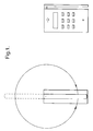
- the movable antenna is in the form of a rod antenna joined to the side of the cellular telephone housing so that it may rotate through 360 degrees.
- the antenna can be rotated manually by a user between a retracted position and an extended position (see Figure 1).
- a portable radio telephone having an antenna which can be pivoted between a first position in which it projects from a surface of the telephone housing, and a second position in which it projects from the surface of the telephone housing, to control the operation of the telephone.
- a portable radio telephone in accordance with the invention may have an advantage that the telephone can be controlled simply by pivoting the antenna between a first position and a second position.
- the antenna of the portable radio telephone projects from a surface of the telephone housing in both the first position and the second position.
- a user can easily pivot the antenna from the first position to the second position or vice versa to control the operation of the telephone.
- This provides an advantage over conventional methods of controlling the operation of a telephone such as, for example, activating keys on a keypad or opening and closing a two-part telephone.
- the use of a pivoting antenna in accordance with the invention may become increasingly advantageous as keys become smaller and more difficult to operate. In some instances the use of a pivoting antenna in accordance with the invention may make the use of a conventional keypad redundant.
- Having the antenna projecting from the surface of the telephone housing in both the first position and the second position may also improve performance of the antenna by providing a better radiation pattern compared to an antenna not projecting from a surface.
- the telephone comprises switching means for switching the telephone between first and second operational states in response to movement of the antenna between the first and second positions.
- the telephone may operate in a first operational state when the antenna is in the first position and in a second operational state when the antenna is in the second position.
- the switching means may respond to movement of the antenna between the first and second positions by sensing the movement of the antenna as it pivots between the two positions.
- the switching means may respond to movement of the antenna between the first and second positions by sensing the antenna reaching the first and/or second positions.
- the first operational state of the telephone is an on-hook state and the second operational state of the telephone is an off-hook state.
- This may provide the advantage that a user may start and end a telephone call by simply moving the antenna back and forth between two predetermined positions.
- the portable telephone may dispose with the conventional 'send' and 'end' keys thus saving space on the keypad of the portable telephone.
- this embodiment may provide a further advantage of allowing the user to answer calls quickly by pivoting the antenna as the telephone is removed from the pocket.
- the first operational state is a powered up state of the telephone and the second operational state is a powered down state of the telephone.
- the telephone includes a user actuable key, whereby in the first operational state the key is enabled and in the second operational state the key is disabled.
- a user actuable key whereby in the first operational state the key is enabled and in the second operational state the key is disabled.
- the telephone further comprises a user interface including illuminating means, whereby in the first operational state the illuminating means is active and in the second operational state the illuminating means is inactive.
- illuminating means whereby in the first operational state the illuminating means is active and in the second operational state the illuminating means is inactive.
- the portable radio telephone further comprises a user interface including voice recognition means, whereby in the first operational state the voice recognition means is active and in the second operational state the voice recognition means is inactive.
- the surface which the antenna projects from is an end surface of the telephone. Ideally the surface is a top surface of the telephone.
- the antenna is a helical antenna which may be substantially axially symmetric.
- the shape of the antenna may be cylindrical, or it may be conical.
- the antenna is attached to the telephone by a hinge arrangement.
- the hinge arrangement permits rotation of the antenna only in a single plane.
- the hinge permits rotation of the antenna only through an acute angle.
- a portable radio telephone 1 consisting of a main body portion 12 and an antenna 13.
- the main body portion 12 of the telephone comprises a generally rectangular housing having a front surface 16, a back surface 17, side surfaces 15, a bottom surface 18, and a top surface 14.
- the main body portion is generally elongate and accordingly defines a major axis, shown as A-A in Figure 2.
- the telephone is designed to be brought into operating proximity with the head of a user as shown in Figure 4 such that in general the front surface 16 faces the head of a user, the back surface 17 faces away from the head of the user, the bottom surface 18 faces downwards, and the top surface 14 faces upwards.
- the main body portion 12 of the telephone 1 includes an earpiece 19 and a microphone 20 both situated on the front surface 16.
- the earpiece 19 and microphone 20 are positioned to cooperate respectively with the ear and mouth of a user as shown in Figure 4.
- the user interface of the telephone 1 further comprises a keypad including keys 21 for controlling the operation of the telephone, and a display 22 (e.g. an LCD display) for displaying information relevant to the operation of the telephone.
- Illuminating means e.g. LED's
- These illuminating means may be switched on or off depending on the operational state of the telephone.
- the antenna 13 of the telephone 1 projects from the top surface 14 such that it extends beyond the housing of the main body portion 12.
- the antenna 13 is a helical antenna having a generally cylindrical shape with a rounded distal end.
- the antenna 13 defines a major axis about which the antenna is axially symmetric.
- the shape of the antenna may take other similarly symmetric forms such as a conical shape. These forms of antenna are often referred to as stub antennas.
- the major axis of the antenna is substantially parallel with the major axis of the main body portion and is normal and perpendicular to the top surface.
- FIG 5a there is shown a side view of another telephone sharing the same features as the telephone in Figure 2.
- the antenna 13 again projects from the top surface 14 such that it extends beyond the housing of the main body portion 12.
- the top surface is curved or rounded.
- the major axis of the antenna is substantially parallel with the major axis of the main body portion and is again normal to the top surface.
- the antenna 13 of the telephone may be pivoted from the upright position shown in Figures 2 and 5a, to an angled or canted position as shown in Figures 3 and 5b.
- the antenna 13 may pivot about an axis B-B such that the major axis of the antenna is substantially perpendicular to axis B-B throughout the rotation of the antenna. Accordingly, the antenna rotates only in a single plane. This single plane is parallel with the side surfaces, perpendicular to the top surface, and perpendicular to the front surface.
- the pivotal rotation of the antenna is limited such that the antenna may only rotate through a small angle ⁇ between the upright position and the angled position as indicated by arrow C in Figures 3 and 5b. In this way the antenna always projects from the top surface of the telephone.
- the antenna When the antenna is in the canted position the angle subtended by the major axis of the main body portion and the major axis of the antenna equals ⁇ . In the canted position the antenna is also directed or orientated away from front surface 16 as shown in Figures 3, 4, and 5b.
- the radio frequency performance of the antenna is affected. This is due to the head of the user disturbing the radiation pattern normally produced by the antenna.
- the antenna performance is improved. This is due to the antenna pivoting away from the head so that the head has less of a disturbing effect on the radiation pattern produced by the antenna.
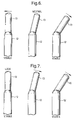
- FIGS 6 to 9 there are shown four possible ways in which an antenna of a telephone in accordance with the present invention may be biased and/or locked as it pivots between the upright and canted positions.
- FIGS 6 to 9 there are shown 3 views, namely a view of the antenna in the upright position, a view of the antenna in the partially canted position, and a view of the antenna in the fully canted position.
- Each arrow in the Figures 5 to 8 refers to the direction in which the antenna is biased.
- the biasing may be provided by, for example, a spring action.
- the antenna is neutrally biased in the partially canted position, and on either side of this position is biased towards the upright and fully canted positions. Accordingly, the antenna is stable in the upright and the fully canted positions.
- the antenna is releasably locked in the upright position, and once released is biased towards the fully canted position. Accordingly, the antenna is stable in the upright and the fully canted positions.
- the antenna is releasably locked in the fully canted position, and once released is biased towards the upright position. Accordingly, the antenna is stable in the upright and the fully canted positions.
- the antenna is always biased towards the fully canted position. Accordingly, the antenna is stable in the fully canted position.
- FIG 10 there is shown the telephone of Figures 5a and 5b being operated by a hand of a user.
- the thumb With the fingers and palm of the hand gripping the main body portion 12, the thumb is free to pivot the antenna 13 from the upright position to the canted position.
- the telephone allows one handed pivoting of the antenna to control the operation of the telephone. It is also possible to pivot the antenna with two hands.
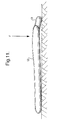
- the antenna of the telephone When storing the telephone of Figure 4a in a pocket, for example, it is desirable to have the antenna of the telephone in the upright position so that the profile of the telephone is minimised. Another instance when it is appropriate to have the antenna in the upright position is when placing the telephone on a flat surface. Sometimes, however, the antenna may be in the canted position when it is placed on a flat surface as shown in Figure 11. In this situation the telephone is likely to experience a downward force on its front surface 16, as indicated by the arrow labelled F. An advantage of the telephone in this situation is that the antenna may adopt the upright position as a consequence of the force F pivoting the antenna relative to the main body portion. Accordingly, the telephone is likely to wobble on the surface and also the antenna is less liable to break or snap as a result of the force F.
- FIGS 12 and 13 are cross-sectional views of the telephone shown in Figures 2 and 3, showing a pivot arrangement for the antenna, and a switch responsive to pivotal movement of the antenna between the upright position and the canted position.
- the antenna 13 pivots about the pivot pin 25 only between the upright position shown in Figure 12 and the angled position shown in Figure 13.
- the pivotal rotation of the antenna is limited in this way by the stop pins 27 which abut the antenna to prevent further pivotal rotation at the extremes of the antenna's rotation.
- a switch 26 is provided in the housing of the main body portion 12 and is coupled to a microprocessor of the telephone to control the operation thereof. The switch 26 is actuated depending on whether a switch actuator 29 on the antenna 13 is in close proximity with the switch.
- the antenna is in the upright position and the switch actuator 29 is not in close proximity with the switch, therefore the switch is not actuated.
- the switch actuator 29 is in close proximity with the switch and the switch is actuated.
- the switch 26 may be a magnetic reed switch and the switch actuator 29 a magnet.
- FIGs 14 and 15 are cross-sectional views of the telephone shown in Figures 2 and 3, showing an alternative pivot arrangement for the antenna, and an alternative switch responsive to pivotal movement of the antenna between the upright position and the canted position.
- the antenna pivots in the same way as in Figures 12 and 13.
- the antenna 13 in this embodiment includes a camming surface 30 which abuts a sprung cam follower 28 in such a way as to produce the biasing action shown in Figure 6.
- the switch 26 is actuated in this embodiment as a result of a surface of the antenna 13 urging the switch closed.
- the antenna is in the upright position and a surface of the antenna pushes the switch closed, therefore the switch is actuated.
- the surface of the antenna does not urge the switch closed and the switch is not actuated.
- the switch may be a leaf switch.
- FIG. 16 Another embodiment in accordance with the invention is shown in Figure 16.
- the main body portion 12 is pen shaped and the antenna 13 extends beyond the housing of the main body portion.
- the main body portion also has a microphone 20 situated towards the bottom of the telephone and a loudspeaker 19 situated towards the top of the telephone.
Landscapes
- Engineering & Computer Science (AREA)
- Computer Networks & Wireless Communication (AREA)
- Signal Processing (AREA)
- Support Of Aerials (AREA)
- Telephone Set Structure (AREA)
- Transceivers (AREA)
Applications Claiming Priority (2)
| Application Number | Priority Date | Filing Date | Title |
|---|---|---|---|
| GB9709466A GB2325109B (en) | 1997-05-09 | 1997-05-09 | Portable radio telephone |
| GB9709466 | 1997-05-09 |
Publications (2)
| Publication Number | Publication Date |
|---|---|
| EP0877492A2 true EP0877492A2 (de) | 1998-11-11 |
| EP0877492A3 EP0877492A3 (de) | 2003-03-19 |
Family
ID=10812081
Family Applications (1)
| Application Number | Title | Priority Date | Filing Date |
|---|---|---|---|
| EP98303565A Withdrawn EP0877492A3 (de) | 1997-05-09 | 1998-05-07 | Antenne für einen tragbaren Funktelefon |
Country Status (3)
| Country | Link |
|---|---|
| US (1) | US6380897B1 (de) |
| EP (1) | EP0877492A3 (de) |
| GB (1) | GB2325109B (de) |
Cited By (3)
| Publication number | Priority date | Publication date | Assignee | Title |
|---|---|---|---|---|
| WO2002052676A3 (en) * | 2000-12-22 | 2003-01-09 | Intel Corp | Communication module with retractable antenae and method therefor |
| EP1009102A3 (de) * | 1998-12-09 | 2003-04-23 | Siemens Aktiengesellschaft | Kommunikationseinrichtung |
| EP2164234A1 (de) * | 2002-07-31 | 2010-03-17 | Panasonic Corporation | Tragbare Funkkomunikationsvorrichtung mit Auslegerabschnitt und Bohrung |
Families Citing this family (13)
| Publication number | Priority date | Publication date | Assignee | Title |
|---|---|---|---|---|
| GB2339509B (en) * | 1998-07-11 | 2004-02-25 | Nec Technologies | Mobile phone with preferential orientation |
| EP1030499B1 (de) * | 1999-02-18 | 2007-01-10 | Robert Bosch Gmbh | Mobiltelefon mit schwenkbarer Antenne |
| EP1221203A2 (de) * | 1999-11-15 | 2002-07-10 | Psion Connect Limited | Entfernbares drahtloses gerät |
| JP3528745B2 (ja) * | 2000-03-06 | 2004-05-24 | 日本電気株式会社 | 携帯無線機 |
| US20020119801A1 (en) * | 2001-02-28 | 2002-08-29 | Yasushi Nemoto | Portable telephone apparatus |
| US6480159B1 (en) * | 2001-08-29 | 2002-11-12 | Auden Techno Corp. | Antenna structure for PDA mobile phone |
| US20040008481A1 (en) * | 2002-07-11 | 2004-01-15 | Samsung Electronics Co., Ltd | Computer system and method of controlling the same |
| JP4134620B2 (ja) * | 2002-07-17 | 2008-08-20 | 日本電気株式会社 | 携帯情報端末 |
| US20050136998A1 (en) * | 2003-12-23 | 2005-06-23 | Spence Michael F. | Spring biased hinge and methods therefor |
| US20050282598A1 (en) * | 2004-06-18 | 2005-12-22 | Hinkey Lawrence A | Antenna and a handle for an electronic device |
| JP2006295364A (ja) * | 2005-04-07 | 2006-10-26 | Matsushita Electric Ind Co Ltd | アンテナ装置 |
| US7880678B2 (en) * | 2008-04-02 | 2011-02-01 | Apple Inc. | Removable antennas for electronic devices |
| US8744539B2 (en) * | 2009-05-01 | 2014-06-03 | Netgear, Inc. | Method and apparatus for controlling radiation characteristics of transmitter of wireless device in correspondence with transmitter orientation |
Family Cites Families (23)
| Publication number | Priority date | Publication date | Assignee | Title |
|---|---|---|---|---|
| DE403532C (de) | 1923-11-10 | 1924-09-29 | Cie Internationale Des Freins | Elektrisch-pneumatische Bremse |
| DE3011160A1 (de) * | 1980-03-22 | 1981-10-01 | Robert Bosch Gmbh, 7000 Stuttgart | Antenne |
| JPS5861554U (ja) * | 1981-10-20 | 1983-04-25 | ソニー株式会社 | トランシ−バ |
| US5014346A (en) * | 1988-01-04 | 1991-05-07 | Motorola, Inc. | Rotatable contactless antenna coupler and antenna |
| FI79210C (fi) | 1988-04-18 | 1989-11-10 | Nokia Mobile Phones Ltd | Foergreningsnaet i kedja foer en basstation i ett radiotelefonnaet. |
| US4897873A (en) * | 1988-11-04 | 1990-01-30 | Motorola, Inc. | Multipurpose hinge apparatus for foldable telephones |
| US4992799A (en) * | 1989-09-28 | 1991-02-12 | Motorola, Inc. | Adaptable antenna |
| GB9102935D0 (en) * | 1991-02-12 | 1991-03-27 | Shaye Communications Ltd | Improvements in and relating to antennae |
| FI89646C (fi) | 1991-03-25 | 1993-10-25 | Nokia Mobile Phones Ltd | Antennstav och foerfarande foer dess framstaellning |
| US5117073A (en) * | 1991-04-02 | 1992-05-26 | Motorola, Inc. | Control signal initiator responsive to a hinge position |
| US5815820A (en) * | 1991-07-12 | 1998-09-29 | Motorola, Inc. | Transmitter having adjustable power levels responsive to the position of a movable antenna |
| GB2257835B (en) | 1991-07-13 | 1995-10-11 | Technophone Ltd | Retractable antenna |
| FI92446C (fi) | 1992-12-22 | 1994-11-10 | Nokia Mobile Phones Ltd | Autoradiopuhelinantenni |
| FR2701613B1 (fr) * | 1993-02-11 | 1995-03-31 | Alcatel Radiotelephone | Appareil émetteur-récepteur radiotéléphonique portatif. |
| JP2689881B2 (ja) | 1993-12-28 | 1997-12-10 | 日本電気株式会社 | アンテナ回転式携帯無線機 |
| US5559522A (en) | 1994-07-25 | 1996-09-24 | Motorola, Inc. | Antenna positioning apparatus capable of substantially vertical orientation |
| US5542106A (en) * | 1994-09-15 | 1996-07-30 | Motorola, Inc. | Electronic device having an RF circuit integrated into a movable housing element |
| JP2658906B2 (ja) | 1994-09-22 | 1997-09-30 | 日本電気株式会社 | 自動オープン式折り畳み携帯電話機 |
| US5590416A (en) | 1995-06-08 | 1996-12-31 | Ericsson Inc. | Canted antenna for a cellular radiotelephone |
| US5657028A (en) | 1995-03-31 | 1997-08-12 | Nokia Moblie Phones Ltd. | Small double C-patch antenna contained in a standard PC card |
| US5627550A (en) | 1995-06-15 | 1997-05-06 | Nokia Mobile Phones Ltd. | Wideband double C-patch antenna including gap-coupled parasitic elements |
| GB2302992B (en) * | 1995-07-05 | 1997-07-23 | Motorola Israel Ltd | Antenna assembly and communications device |
| US5680144A (en) | 1996-03-13 | 1997-10-21 | Nokia Mobile Phones Limited | Wideband, stacked double C-patch antenna having gap-coupled parasitic elements |
-
1997
- 1997-05-09 GB GB9709466A patent/GB2325109B/en not_active Expired - Fee Related
-
1998
- 1998-05-07 EP EP98303565A patent/EP0877492A3/de not_active Withdrawn
- 1998-05-07 US US09/074,243 patent/US6380897B1/en not_active Expired - Fee Related
Cited By (6)
| Publication number | Priority date | Publication date | Assignee | Title |
|---|---|---|---|---|
| EP1009102A3 (de) * | 1998-12-09 | 2003-04-23 | Siemens Aktiengesellschaft | Kommunikationseinrichtung |
| WO2002052676A3 (en) * | 2000-12-22 | 2003-01-09 | Intel Corp | Communication module with retractable antenae and method therefor |
| GB2387299A (en) * | 2000-12-22 | 2003-10-08 | Intel Corp | Communication module with retractable antenae and method therefor |
| GB2387299B (en) * | 2000-12-22 | 2005-02-09 | Intel Corp | Communication module with retractable antennae and method therefor |
| US7620435B2 (en) | 2000-12-22 | 2009-11-17 | Intel Corporation | Communication module with retractable antennae and method therefor |
| EP2164234A1 (de) * | 2002-07-31 | 2010-03-17 | Panasonic Corporation | Tragbare Funkkomunikationsvorrichtung mit Auslegerabschnitt und Bohrung |
Also Published As
| Publication number | Publication date |
|---|---|
| GB2325109A (en) | 1998-11-11 |
| GB9709466D0 (en) | 1997-07-02 |
| GB2325109B (en) | 2001-08-22 |
| US6380897B1 (en) | 2002-04-30 |
| EP0877492A3 (de) | 2003-03-19 |
Similar Documents
| Publication | Publication Date | Title |
|---|---|---|
| US6380897B1 (en) | Portable radio telephone | |
| EP0661824B1 (de) | Faltbares und tragbares Funktelefon mit verbesserter Antennenausbeute | |
| US5615259A (en) | Integral flap housing, switch actuator and detent mechanism for a foldable telephone | |
| KR930009847B1 (ko) | 접는 전화기용 힌지장치 | |
| US7200428B2 (en) | Portable terminal | |
| JP3915006B2 (ja) | 無線電話 | |
| EP1385319B1 (de) | Selbstbetriebener Öffnungsmechanismus zum Gebrauch in einem tragbaren elektronischen Gerät | |
| US20050137000A1 (en) | Rotatable latching device for a housing of a portable electronic device | |
| CN1255263A (zh) | 便携式通信装置以及通过它的电源键实行多种功能的方法 | |
| US6850773B1 (en) | Antenna system for a wrist communication device | |
| EP0961458B1 (de) | Tragbares Funkgerät | |
| KR200211457Y1 (ko) | 플립형 휴대전화기 | |
| US7142667B2 (en) | Self operating opening mechanism for use in hand-held electronic device | |
| US7706847B1 (en) | Portable radio telephone | |
| KR20010034639A (ko) | 이동 전화기의 플립 힌지 장치 | |
| KR100312546B1 (ko) | 외면에 디스플레이가 장착된 덮개가 슬라이딩개폐되는 폴더형휴대폰 | |
| US20020061733A1 (en) | Unfolding apparatus for foldable electronic device | |
| MXPA05000964A (es) | Mecanismo de abertura automatica para dispositivo electronico. | |
| KR100428423B1 (ko) | 이동통신단말기의 커버 개폐장치 | |
| KR200330255Y1 (ko) | 폴더형 단말기의 커버 개폐장치 | |
| KR200184935Y1 (ko) | 휴대폰 | |
| JP2007180853A (ja) | 電子機器及び携帯電話機 | |
| KR960027495A (ko) | 안테나를 이용한 손목착용용 무선전화기의 수신 및 발신장치 및 그 제어방법 | |
| KR100334776B1 (ko) | 단말기에서 자동 폴더의 시각적 통보장치 | |
| KR200235541Y1 (ko) | 이동통신단말기의 커버 개폐장치 |
Legal Events
| Date | Code | Title | Description |
|---|---|---|---|
| PUAI | Public reference made under article 153(3) epc to a published international application that has entered the european phase |
Free format text: ORIGINAL CODE: 0009012 |
|
| AK | Designated contracting states |
Kind code of ref document: A2 Designated state(s): AT BE CH CY DE DK ES FI FR GB GR IE IT LI LU MC NL PT SE |
|
| AX | Request for extension of the european patent |
Free format text: AL;LT;LV;MK;RO;SI |
|
| RIN1 | Information on inventor provided before grant (corrected) |
Inventor name: HOOKER, GUY Inventor name: CHAAYA, ELIE ABI Inventor name: PRIOR, SEAN Inventor name: GOCOOL, ARNOLD Inventor name: TOUT, NIGEL Inventor name: DURHAM, GUY Inventor name: SHAW, CONWAY |
|
| PGFP | Annual fee paid to national office [announced via postgrant information from national office to epo] |
Ref country code: DK Payment date: 20010919 Year of fee payment: 4 |
|
| RAP1 | Party data changed (applicant data changed or rights of an application transferred) |
Owner name: NOKIA CORPORATION |
|
| PUAL | Search report despatched |
Free format text: ORIGINAL CODE: 0009013 |
|
| AK | Designated contracting states |
Kind code of ref document: A3 Designated state(s): AT BE CH CY DE DK ES FI FR GB GR IE IT LI LU MC NL PT SE |
|
| AX | Request for extension of the european patent |
Extension state: AL LT LV MK RO SI |
|
| RIC1 | Information provided on ipc code assigned before grant |
Ipc: 7H 01Q 1/08 B Ipc: 7H 01Q 1/24 B Ipc: 7H 04B 1/38 A |
|
| STAA | Information on the status of an ep patent application or granted ep patent |
Free format text: STATUS: THE APPLICATION HAS BEEN WITHDRAWN |
|
| 18W | Application withdrawn |
Effective date: 20030211 |