EP0877657B1 - Moules et noyaux de moule pour moulage a la cire perdue - Google Patents
Moules et noyaux de moule pour moulage a la cire perdue Download PDFInfo
- Publication number
- EP0877657B1 EP0877657B1 EP96924390A EP96924390A EP0877657B1 EP 0877657 B1 EP0877657 B1 EP 0877657B1 EP 96924390 A EP96924390 A EP 96924390A EP 96924390 A EP96924390 A EP 96924390A EP 0877657 B1 EP0877657 B1 EP 0877657B1
- Authority
- EP
- European Patent Office
- Prior art keywords
- mold
- ceramic
- casting
- core
- machining
- Prior art date
- Legal status (The legal status is an assumption and is not a legal conclusion. Google has not performed a legal analysis and makes no representation as to the accuracy of the status listed.)
- Expired - Lifetime
Links
Images
Classifications
-
- B—PERFORMING OPERATIONS; TRANSPORTING
- B22—CASTING; POWDER METALLURGY
- B22C—FOUNDRY MOULDING
- B22C9/00—Moulds or cores; Moulding processes
Definitions
- the present invention relates to the field of investment casting.
- Investment cast articles are widely used in most industries, and improved production techniques are of great importance.
- Investment casting is an old art, but one that holds considerable continuing import in many industries, and is the technique of choice in the fabrication of intricately shaped parts and particularly of parts having complex or inaccessible internal bores, cavities, or chambers.
- investment casting is based on the formation of a part to be formed in wax or a wax-like material, dimensioned to allow for shrinkage of the cast as it cools, which is coated with ceramic refractory shell.
- the wax material is removed from the shell, leaving a cavity having the conformation of the original wax part.
- the ceramic is fired to sinter the particles, forming a solid mold having a cavity adapted to receive molten metal.
- the cavity is filled with molten metal, which is then cooled to solid form.
- the shell is removed, by hammering or sand blasting or the like, and the cast recovered.
- a finished part is provided.
- the dimensional precision of investment castings can be quite respectable, and the grinding operation employed as an element of finishing can produce parts of substantially any degree ot precision and accuracy required.
- mold core inserts When mold core inserts are employed, they are commonly formed separately from the shell, of refractory ceramic materials the same as or comparable to those employed to form the mold shell. Like the shell into which they are inset, cores or inserts must be dimensioned to allow for shrinkage, and must be placed, positioned and supported within the shell with accuracy and precision.
- the core material is removed by techniques generally the same as those employed for removing the shell, which may be supplemented by chemical removal of the material in regions that are not accessible to hammering or sand blasting operation.
- chemical removal may limit the selection of materials for the core.
- mold inserts and cores There are a variety of techniques for forming mold inserts and cores, which may be of quite elaborate and delicate shapes and dimensions. An equally diverse number of techniques are employed to position and support the inserts in the shells.
- the most common technique for supporting cores within mold structures is the placement of modestly sized ceramic pins, which may be formed integrally with the shell or the core or both, which project from the surface of the shell to the surface of the core structure, and serve to locate and support the core insert.
- the holes in the casting are filled, as by welding or the like, preferable with the alloy of which the casting is formed.
- mold shell and core formation have been limited in the ability to reliably form fine detail with reasonable levels of resolution.
- reliable dimensions, and the generation of intricate and detailed shapes have been quite limited.
- the core inserts are typically castings or moldings, employing usual ceramic casting or molding, followed by appropriate firing techniques. It is inherent in the nature of ceramic casting that accuracy and precision are substantially less than those achieved by metal casting techniques. There is far greater shrinkage in the usual ceramic casting formulations or "slips" with a much greater tendency to form cracks, bubbles, and other defects. There is accordingly a high failure and reject rate in the production of metal investment castings stemming from incorrectable defects caused by faulty cores and core placement, and a high casting working requirement to correct those castings which are out of specifications, but amenable to correction by machining, grinding and the like. The productivity and efficiency of investment casting operations are substantially hindered by such requirements.
- Another object is to reduce the tool development cycle to produce investment casting molds and cores of high accuracy and dimensions.
- Still another object is to provide techniques for the reclamation of investment casting molds which are out of allowable specifications, to produce castings of high precision and accuracy.
- Yet another object of the present invention is the provision of techniques to alter the shape and dimensions of investment casting molds and cores to provide for design changes without repeating the tool development cycle
- the present invention provides a method of producing investment cast articles by investment casting with a ceramic mold, the method comprising the steps of:
- the present invention further provides a method of producing a method of producing investment cast articles by investment casting with a ceramic mold, the method comprising the steps of:
- investment casting molds and particularly mold core inserts of high and reproducible accuracy and precision are formed by casting the core insert of a ceramic, firing the ceramic, and machining the ceramic shell or core element to the required degree of accuracy and precision by the use of one or more ultrasonic machining techniques, and particularly form machining techniques on the fired ceramic.
- the shell or core insert may be machined from blocks or "bar stock" of presintered ceramic material with uniform porosity to allow for shrinkage in subsequent processing and handling, and the surfaces may be coated after machining to provide a smooth surface for casting.
- the smooth surface of the ceramic will produce a corresponding smooth surface on the metal casting to be formed in the mold. It is possible to make such blocks or "bar stock" of pre-sintered ceramic materials with very uniform and highly predictable shrinkage properties, permitting a more precise casting compared with cores that are formed by the techniques usual in the art whose porosity and shrinkage properties may vary considerably.
- One of the greatest benefits of the procedures of the present invention is the reduction of the lead-time to produce parts, and the acceleration of the process of developing the molds.
- the iterative process of development common in the art is greatly reduced because there is no need to achieve a final shape which produces a net dimensioned mold configuration in the ceramic casting or molding operation. Since the net mold shapes can be readily adjusted, producing castings of the desired form and dimensions is not the difficult and time consuming, largely trial and error process commenly required in the art.
- molds, and particularly cores, for investment casting are worked to the required degree of precision and accuracy of form and dimensions after firing to a fully sintered condition.
- the ultrasonic machining technique provides substantial advantages. It is immaterial that the ceramic structures are non-conductive and complex; three-dimensioned forms can be machined as readily and as rapidly as simple ones. There are no chemical or thermal alterations of the surfaces.
- the procedures of the present invention are particularly significant to mold core inserts, because of the inaccessibility of the internal bores and cavities of castings for correction by traditional machining procedures, such as grinding, polishing, and the like, the present invention provides the first technique which is practical for the correction of mold components prior to casting, so that the casting is of greater precision and accuracy, saving the need for much of the working or castings. While working the fired mold shell may not be cost effective in all cases, it can represent significant improvements in some very complex and difficult to work shapes, and will be productive in such circumstances.
- green bodies are formed by techniques which are conventional in the art. There are not specific consideration which are required to adapt the green bodies to the practice of the present invention, although there are some preferred features which may be desirable to maximize the benefits to be realized.
- compositions commonly employed in the art can be employed with the present invention. It is generally preferred that the formulations which are least in cost and highest in performance in the casting and mold removal procedures be employed; it is not necessary that the complex formulations developed to minimize shrinkage upon firing of the green bodies be employed. Such formulations often involve more expensive and demanding materials to work with, and may offer compromised performance during the pour of the molten metal or during the cooling of the casting. Such materials are often more difficult to clean from the casting as well. Because such "improved" formulations are unnecessary, we prefer to avoid their use in the present invention.
- finishing operations such as grinding and polishing of investment castings are time consuming, labor intensive, and expensive aspects of foundry practice, ail improvements in the as-cast conditions of the castings which serve to minimize the finishing operations and the need for corrections, the greater the productivity, efficiency and economy of production.
- green body binders are not critical to the present invention, for the same reasons set out above.
- the green bodies will not be subjected to working to control dimensions, and for that reason, the green body strength, often dictated primarily by the selection of the binder formulation to withstand the requirements of such working, is not as significant to the formation of green bodies for use in the present invention.
- less expensive materials may be used, with attendant savings in the cost of the forming operation.
- the binder may be a water soluble inorganic binder, such as water glass, a water soluble organic polymer, such as polyvinyl acetate or polyvinyl alcohol, or a natural or synthetic polymer hydrogel, such as guar gum or poly(hydroxyethyl methacrylate), or the like.
- the binder may be a plastic binary, particularly a thermoplastic polymer binder, or a polymer which can be thermoset after forming by the application of heat, such as phenolics, polyepoxides, polyurethanes and the like. (Such materials are removed by thermal degradation during firing operations, and are not generally present when the machining operations of the present invention arc employed.)
- the low strength requirements of the green bodies in the present invention will permit the dilution of the ceramic formulation with inert refractory diluents as fillers in the composition, affording still greater saving in material costs.
- the present invention permits the use of fillers to facilitate the molding and casting characteristics of the ceramic molding formulations or slips, which can materially aid the facility of forming the green bodies.
- fillers to facilitate the molding and casting characteristics of the ceramic molding formulations or slips, which can materially aid the facility of forming the green bodies.
- the ceramic green body forms of the present invention maybe formed by any of the usual techniques employed in the art. Including by way of example casting of fluid dispersions molding of plastic dispersions, and static pressing.
- the casting technique employed is not a major factor in the quality or productivity of the operation, and can be selected on the basis of convenience and cost considerations in most circumstances.
- Dip casting may be the technique of choice for the formation of mold shells, wherein the wax form is dipped into a slip, or dispersion of the ceramic components in a fluid, frequently an aqueous medium with a water soluble or hydrogel binder.
- the solids deposit on the surface of the form, and form a coating conforming to the shape of the form.
- Spray coating of the ceramic slip may also be employed.
- Dip casting techniques are less favored for the formation of cores, as the control of the process is more difficult when the ceramic is deposited on the interior of female forms. It is common to have void which represent defects in the green bodies when the mold is removed. For that reason, molding procedures are generally preferred for the formation of cores.
- the ceramic formulation is dispersed in a suitable binder to form a plastic molding composition, which is formed in a female mold or form.
- the forming may be accomplished by injection molding at relatively elevated temperature, or any of the many related plastic molding variations know in the art
- the formed green bodies may be enhanced, in some cases, by isostatic pressing, including hot pressing, to density the ceramic materials prior to firing.
- the green bodies may be reinforced by the inclusion of fibrous reinforcing or armatures, formed of ceramic or metallic fibers, to support the structural elements of the form.
- ceramic or metallic fibers are included, it is preferred they not be incorporated into the slip or molding formulation which forms the surface or is subjected to subsequent working.
- the firing of the green bodies is the least controllable and least predictable step in the formation of investment casting molds, and the one most determinative of the quality of the casting to be produced.
- the present invention does not operate to make the procedures more controllable or more predictable; in the present invention, the quality of the shape, dimensions and surface finish of the mold elements and the resulting shapes, dimensions and surface finish of the casting to be produced in the mold are not controlled by the firing step, or by the condition of the mold elements as fired. Firing is accordingly a far less demanding aspect of the practice of investment casting in the present invention. Since the shape and dimension of the fired mold are to be worked in the present invention, it is sufficient to achieve a near net shape in the fired body prior to working.
- the firing operation itself will be dictated by the sinter requirements of the ceramic and the burn-out requirements of the green body binder. Heating schedules, holding time at temperature, and cooling schedules are known in the art and are not altered in the present invention.
- the present invention does not eliminate the requirements of good design and fabrication practice in the development of green bodies.
- the ceramic material Upon firing, the ceramic material will still undergo the usual amounts of shrinkage, and care must be taken to avoid slumping and cracking of the form during the firing operation.
- the extent of working of the fired mold elements will be dictated in large measure by the quality of the fired body, which is in turn dictated by the quality of the green body.
- the green body should accordingly be near the required shape and dimensions, developed to produce a fired ceramic of good quality and near the required net shape and dimensions necessary to produce the designated casting.
- the green bodies be produced to such a "near-net" shape, with any variation from the target, net shape required in the casting operation favoring an over-sized green body. It is greatly preferred that the green body not be undersize.
- the green body should be developed to produce a fired mold which is at specifications, pius 1mm, minus zero, preferably plus 0.1 mm, minus zero.
- a fired mold which is at specifications, pius 1mm, minus zero, preferably plus 0.1 mm, minus zero.
- the structural and physical properties of the green bodies and the fired ceramic bodies are not altered in the present invention, and those of ordinary skill in the art will fully understand that these forms must treated with some care.
- the fired bodies in particular, are hard, brittle and relatively fragile materials.
- the shell or core insert machined from standardized "blocks" or “bar stock” of presintered ceramic material can be formed with superior uniformity, and particularly uniform porosity to allow in turn for uniform and highly predictable shrinkage in subsequent processing and handling.
- the "stock material” is formed into the net shape required by the ultrasonic machining technique of the present invention, and the surfaces may be coated after machining to provide a smooth surface for casting; the coated shape may be re-fired, if required or wanted to fix the coating, depending on the composition employed.
- the smooth surface of the ceramic will produce a corresponding smooth surface on the metal casting to be formed in the mold. It is possible to make such blocks or "bar stock" of pre-sintered ceramic materials with very uniform and highly predictable shrinkage properties, permitting a more precise casting compared with cores that are formed by the techniques usual in the art whose porosity and shrinkage properties may vary considerably.
- a mold core or shell is produced which is near, but not at, the net required shape and dimensions, and is then worked to machine the mold element to the final required shape and dimension, with a highly developed surface finish, with high levels of precision and accuracy.
- the machining techniques can be employed to refine the fired mold elements, but it can also be employed to produce modifications in the mold, to afford features not readily produced in the usual forming operations. Small holes may he drilled into or through the mold structure, for example, with a precision in location, regularity and dimensions not practical in usual mold making operation.
- Investment casting molds are often complex structures, corresponding to the castings to be produced.
- such molds require the normal additional parts required to make the casting, including, for example, sprues, gates, pouring cups, and the like.
- Such procedures will ordinarily be preferred in the present invention as well, although it is worthy of note that additions can be cemented in place on the green body prior to firing, or to the fired mold, either before or after the working contemplated by the present invention.
- Ultrasonic machining has become increasingly important in recent times for a variety of applications. It has been used to machine ceramics, among other materials, in a variety of contexts. It has not been employed in investment casting processes, or to work investment casting molds and mold components because the art has concentrated on other methodologies to produce superior molds. As noted above, it has generally been easier to alter the wax forms, adapt ceramic formulations or to work green bodies at earlier stages in the process, since these materials are far easier to work.
- Ultrasonic machining is reasonably developed in the art for working a variety of materials, including ceramic materials.
- a tool or sonotrode is developed having the desired conformation, and is mounted on a transducer which is caused to vibrate at ultrasonic frequencies, as by piezoelectric effects and the like.
- the tool or sonotrode is advanced onto the surface of a workpiece, with an abrasive medium interposed between the tool or sonotrode and workpiece surface.
- the vibrations are transmitted through the abrasive to effect working of the workpiece surface. Excitation of the abrasive particulars abrades the workpiece surface leaving a precise reverse form of the tool or sonotrode shape.
- the working surface area of the tool or sonotrode is generally limited to no more than about 100 cm 2 , so that when larger areas are to be worked, the part or the transducer must be moved to different locations and again worked, often with a different tool or sonotrodc, having different form suited to the particular area to be machined.
- Lower frequencies, in the sonic range may be used if desired, and are within the scope of the our usage of the term "ultrasonic machining" as employed herein.
- the fired mold or mold components can be machined, cut or bored as required. While such machining operations are not common to mold making operations, the introduction of the present invention permits the development of structures net heretofore practical in casting operations or, more often, limited to the development of coarse structures which require reworking of the casting formed in the mold after it is formed.
- the present invention will be employed to grind the surfaces of the fired mold or mold components to net size and shape from near-net conditions achieved in the original formation of the ceramic body.
- the ultrasonic machining techniques can grind the fired ceramic to dimensional tolerances substantially as closely as required, typically to - 0, + 0.1mm, ordinarily on the order of -0, + 0.05mm or less and, if required, to -0, + 0.02mm.
- the dimensions are typically as fine as the grain size of the sintered ceramic, which is generally the limiting parameter of accuracy and precision in such grinding operations.
- the surface roughness can be readily reduced by ultrasonic polishing of the surfaces of the ground ceramic body, down to the limits of the grain size and porosity of the sintered ceramic. Further reductions in roughness may achieved by employing machining conditions which will machine the individual grains at the surface. For adequately dense ceramics, a glass-smooth surface, having a surface roughness of as little as 0.01 mm RMS, can be achieved, but is not often indicated or required.
- transducer components are commercially available, and any may be employed in the present invention which will convert the electrical signals produced in the generator into mechanical vibration at the appropriate applied frequency, typically by a piezoelectric effect, coupled to a booster which serves to amplify (or sometimes suppress) the amplitude of the vibrations.
- the tools or sonotrodes which impart the vibration of the transducer to the abrasive to effect the machining operation.
- the sonotrode is typically a metal rod or bar of a suitable metal which has a resonant length suited to the frequency of the vibrations to be produced, for metals such as steel, aluminum or titanium, typical resonant lengths are from about 100 to about150mm, most often about 115 to about 140mm.
- the machining surfaces of the ultrasonic machining tool or sonotrode can be varied over wide limits, from quite small "point machining" tools having a working area of less than about 1mm 2 up to a current maximum of about 100 cm 2 . Small point machining tools are particularly appropriate for prototyping work, and may be helpful in final finishing and detailing operations in production, while larger area form tools are appropriate for production tooling.
- the small "point machining” tools can be formed into variety of small shapes, including spherical, squared, circular, or conic sections, including truncated conic sections, and the like, to afford a convenient assortment to suit the particular machining requirements of particular operations.
- machining tools are generally shaped to directly produce the required shape, including three dimensional form, detailing and dimensions required of the fired ceramic.
- the shape of the tool or sonotrode will be a mirror image of the ceramic form to be machined, with suitable allowances for the gap between the tool or sonotrode and the fired ceramic.
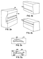
- Plural form tools are illustrated in stylized fashion in Figure 2, wherein a workpiece (50) is supported in a holder (60). A pair of ultrasonic machining tools (70, 80) are shown in faced opposition to the holder (60) and workpiece (50). The face of each tool is a negative image of the designed configuration of a corresponding portion of the workpiece surface.
- the workpiece is in the shape of a highly stylized and simplified form of a core insert for molding a turbine engine blade.
- the workpiece (50) is mounted in the holder (60), which is in turn mounted on a suitable support, not shown.
- One of the ultrasonic machining tools is mounted on a sonotrode carried on a ram to advance the tool into working position in relation to the workpiece, also not shown.
- the tool is advanced to machine a portion of the surface of the workpiece surface in registration and alignment. Once the machining with the first tool is complete, the tool is removed and replaced by the second tool, and the second tool is then advanced into working position in registration and alignment with the corresponding and mating surface portion of the workpiece, and performs the required machining on that portion of the workpiece surface.
- any of the many tool materials commonly employed in forming ultrasonic machining tools may suitably be employed in the present invention. Most common in the art is the employment of high speed tool steel, although in may cases, more abrasion resistant steel and non-ferrous alloys are employed. The selection of appropriate tool or sonotrode materials is not a critical feature of the present invention.
- the tool or sonotrode may be formed directly into the ultrasonic array, or may be separately formed and affixed to the working surface, of the sonotrode, by brazing or the like.
- the required shape and form of the tool may produced by any suitable machining technique.
- Such techniques also facilitate redressing of the tool or sonotrode as it becomes worn during ultrasonic machining operations.
- Form tools may be provided with any shape desired, and with fine detailing as desired, providing the following constraints are observed:
- the shape must be consistent with an axial advance of the transducer and tool or sonotrode into engagement with the ceramic structure to be machined.
- the tool or sonotrode cannot make undercuts, and separate machining operations, with a different orientation of the transducer and a different tool or sonotrode are generally required to produce undercut shapes. Because of the added complexity of the machining operation involved, such design features should be avoided whenever possible. although when required, additional operations can accommodate most shape requirements.
- the minimum dimensions that can be tolerated are dictated primarily by the characteristics of the ceramic material. Since the ceramic to be worked is already fired, it will have far greater strength and durability in many respects than an unfired green body, but as the dimensions are reduced in thin walled, finely detailed structures, great care must be taken. It is may be desirable to design such features with at least some taper, if possible, to facilitate the advance and retraction of the tool or sonotrode and transducer without direct contact. A taper as little as one degree will be of some help, but when possible, a taper of 3 to 5 degrees is more typically employed. A taper is not a critical requirement, as the dimension of the cut will provide the gap between the tool or sonotrode and the workpiece, discussed above, on the order of at least about twice the diameter of the abrasive particles in the gap.
- form tools be limited in size, as noted above, to no more than 100 cm 2 . It is also convenient to limit the maximum dimensions of the tool or sonotrode to fit with in a circle having a radium of about 15cm.
- the tool or sonotrode surfaces are generally formed of wear resistant materials, and in the case of machining, cutting and grinding operations, the material is more resistant to the ultrasonic machining effect of the operation than the ceramic workpiece, there will be wear, and over time the tolcrances required of the tool will reach the limit of acceptability. At that point, the tool or sonotrode must be redressed. to restore the appropriate shape and dimensions, or be replaced by another, fresh tool.
- the tool or sonotrode will not lose tolerances until a substantial number of parts have been produced within acceptable tolerances.
- each tool or sonotrode may be redressed multiple times before too much material is lost to permit further redressing and reuse.
- the abrasive work required in ultrasonic machining, grinding and polishing operations is most often performed by abrasive particles, dispersed in a fluid carrier, which is vibrated by the ultrasonic tool or sonotrode.
- abrasive particles dispersed in a fluid carrier, which is vibrated by the ultrasonic tool or sonotrode.
- the tool or sonotrode is thus never brought into direct contact with the work surface, and a gap is maintained between the tool or sonotrode and the workpiece. It is possible to avoid breakage of the tool or sonotrode through impact with the work, and to assure a flow of fresh, unworn abrasive into the gap during the operation.
- the debris generated by the working of the workpiece is washed away from the interface gap, and does not build up to levels which might interfere with the operation.
- the fluid is employed to suspend and transport the abrasive into and out of the gap between the tool and the workpiece, to carry heat from the gap, and to flush the debris of the working operation out of the gap.
- the nature of the fluid is not a critical matter so long as it is compatible with the tool, the ceramic and can perform the indicated functions. Any of the fluids commonly employed in the art may suitably be employed.
- abrasives may be employed in the present invention, including all those typically used in prior art ultrasonic machining processes.
- ceramic materials to be worked in the present invention we prefer to employ silicon carbide for relatively low density ceramics, such as silicon oxide and alumina based ceramics, and boron carbide to work high density ceramics formed of silicon nitride and silicon carbide.
- the particles sizes of the abrasive are preferably on the order of about 25 to 75 mm in diameter, although when desired a broader range may be employed, so long as the gap dimensions between the tool or sonotrode and the ceramic workpiece are adjusted accordingly.
- the frequency of the ultrasonic machining vibrations will normally be in the range of from about 200 to about 30,000 Hz. In some circumstances, lower or higher frequencies may prove more effective in working particular ceramics or in employing particular tool or sonotrode materials or both.
- the desired frequencies are those at which the combination of transducer, including any booster element, and the tool or sonotrode are resonant.
- the resonant frequency is in the range of from about 15,000 to about 25,000 Hz, and preferably about 19,000 to about 21,000.
- the amplitude of the oscillations during the machining operation is generally on the order of about 1 to about 1,000 micrometers, most often 10 to 250 micrometers, and preferably about 25 to about 50 micrometers.
- the optimum frequency and amplitude will vary with the composition of the ceramic of which the mold is formed, and is readily determined by empirical techniques. It will be found, however, that the degree of improvement in optimum conditions does not vary greatly from other frequencies and amplitudes, and it is quite possible to operate at a fixed frequency and a fixed amplitude for all mold materials if desired.
- the machining speeds typically achieved in working the ceramic materials in the present invention provide material removal at a rate typically on the order of 0.25 to 100 mm 3 per minute, varying with the amplitude of vibration, the abrasive grain size, and the specific characteristics of the ceramic.
- the rate of advance or penetration rate will correspondingly be on the order of about 0.25 mm to about 2.5 mm per minute, depending on the hardness and density of the ceramic.
- Typical surface finishes as worked will range from about 0.2 to about 1.5 ⁇ m RMS, with accuracies of - 0, + 0.1 mm typical, and when required, tolerances of as little as -0, +2 ⁇ m can be attained.
- a matched pair of supports, for the opposite faces of the mold or mold component, will ordinarily permit complete working of the workpiece in two sequential operations, while supported in each support fixture.
- the effectiveness of the work is often enhanced by adding to the oscillations a periodic, preferably intermittent, relatively large amplitude reciprocation of the tool or sonotrode relative to the surface of the ceramic body.
- a periodic, preferably intermittent, relatively large amplitude reciprocation of the tool or sonotrode relative to the surface of the ceramic body serves to "pump" the fluid and abrasive medium in the gap between the tool or sonotrode and the ceramic surface to assure a fresh supply of abrasive and a high homogeneity of the cutting medium.
- the orientation of the abrasive particles in the gap is changed during each pulse by a tumbling action during such reciprocations, assuring that fresh cutting edges and points are presented to the ceramic surface throughout the duration of the operation.
- a reciprocation of about 0.1 to 2.5 millimeters, at a frequency of about 0.1 to 5 Hz, for a duration of one or two cycles, will be effective for such purposes.
- orbital motion can accelerate the cutting action on the ceramic surface by combining features of orbital grinding with the ultrasonic machining effects.
- the orbital motion serves to assure the homogeneity of the cutting medium in the gap between the tool and the ceramic surface, and to impart a working component of its own in a "lapping" type of action.
- the transducer and tool or sonotrode on a hydraulically, electrically or pneumatically driven ram, preferably in a tool changer mechanism of the general type commonly employed in the machine tool art, to facilitate rapid tool changes when required, and to assure precise and reproducible alignment of the tool.
- the ceramic workpiece will typically be mounted in a fixture which positions, aligns, and registers the workpiece to the tool.
- the abrasive suspended in its liquid carrier may be introduced into the gap from one or more points located at the edge ot the gap or through conduits provided through the sonotrode or the workpiece.
- the suspension is typically captured and recycled, preferably with cooling.
- the ram is advanced to establish the correct gap and the generator is actuated to commence the machining operation.
- the ram is then advanced at a rate consistent with the rate of stock removal from the ceramic until the desired limit is achieved. It is often desirable to periodically interrupt the operation, retract the tool and then advance it into operating engagement again.
- the superimposition of such a periodic axial oscillation serves to force accumulated debris and worn abrasive out of the gap, and is aided by the flushing action of the imposed flow of the abrasive suspension.
- the action also provides enhancement of the cooling effect of the liquid flow in the gap. Both effects promote the precision of the machining operation.
- the amplitude is not critical and may range from 0.1 mm to 2.5 mm, and may occur at a pulse rate of from about once in five minutes to as often as 5 Hz. Typically, about one pulse every 10 - 30 seconds will be convenient.
- the machining operation will often require the use of two or more tools. Often the axis of the relative motions required will differ.
- Such features may be provided in separate operations in serial fashion on separate equipment, or a single machine may be provided with plural rams at different alignments to the ceramic or more typically, the fixturing can be adapted to provide differing alignments, either by re-orienting a single fixture or providing a plurality of fixtures. When opposite sides of each ceramic workpiece are to be machined, it will generally be necessary to employ at least two fixtures.
- the tolerances of the machining operation are conveniently monitored by conventional measuring and gauging techniques. Since the ceramic is normally non-conductive, contact-type measurements are generally preferred. It may be convenient to indirectly gauge the workpiece by measuring the tool, by contact or non-contact techniques to monitor wear, with periodic measurements of all or an appropriate sample of machined workpieces after the machining is complete. Since the cutting characteristics are very precisely predictable for a given operation, and since the engagement of the tool in relation to the fixture can be equally precisely controlled and reproduced, it may be unnecessary to measure the part itself during the machining operation.
- the positioning of a core element in a waxing mold is exemplary of the acute problems that can arise in casting. Despite the quality of the waxing mold and the core insert, any error in positioning the core within the waxing mold wher the wax medium is injected will introduce a reduced wall thickness where the core is positioned too close to the mold wall, and a corresponding increased wall thickness in opposition. Such errors often are resolved by over-design of components, adding surplus weight and material to cast parts.
- core locating pins integrally molded into the core structure or, more commonly, mounted on a core holding fixture developed within the waxing mold.
- Such pins leave a hole within the wax pattern when separated from the waxing mold which may be filled by customary wax pattern finishing techniques, or which in some cases may be left in place to be filled with the ceramic formulation in subsequent dipping to produce a corresponding hole through the casting.
- Such holes are often desired, for example, to provide cooling air flow from the hollow core to the surface in the case of turbine engine blades, although locating pins of a diameter suited to such air flow porting may be rather fragile.
- datum points will be dictated by the design of the core and the locating pins to be employed.
- a point tool or form tool to conform the datum point conformation to mate with and engage the ends of the pins is undemanding. Ultrasonic machining limited to the formation of such datum points can be quite rapid, even at very tight tolerances.
- the castings produced in the present invention require little or no surface working to correct the dimensions, even to the extent that the surface finish of the molds are of much greater importance.
- the part can be employed as cast, with no grinding of the cast surface, and a good surface finish is often necessary to obtain the full benefits of the invention.
- surface finish of the ceramic parts may formed, ground and polished to substantially any degree of dimensional accuracy and precision, and any level of surface finish required in the casting. It should be noted, however, that polishing of the mold surfaces may be limited by the shrinkage of the casting during the cooling of the metal melt to a solid phase, and during the cooling of the solid, since the shrinkage may draw the casting out of contact with the surface of the mold before the surface is fully solidified, and permitting the alteration of the surface finish imparted by the mold surface by syneresis. Polishing the mold beyond the limits of the casting operation is self evidently unnecessary and wasteful, and should not be employed. The appropriate limits to be employed are a function of the size of the casting and the shrinkage characteristics as the pour cools and solidifies. An as-cast surface finish of better than about 10 microinches RMS is generally not obtained by casting of metals.
- the pour of molten metal into the molds made by the present invention are not altered by the present invention, and good molding practice well understood in the art is fully effective.
- Such techniques as centrifugal casting, where the mold and the molten metal are rotated to enhance flow of the melt into the mold cavities and to achieve other beneficial effects may be employed with the present invention to good effect.
- a cooling schedule will be dictated by the characteristics of the metal of which the casting is being formed. These requirements are not altered by the present invention, and are generally known to those of ordinary skill in the art
- the mold is removed.
- the shell is most often removed by mechanical means, including hammer and/or sand blasting.
- Internal cores may be removed by hammering or sand blasting in some cases. In others, the core will not be accessible to such techniques, and may require chemical or solvation effects to achieve proper and sufficient removal. These are techniques which are in common use and well known to those of ordinary skill in the art.
- the ceramic material must be chosen from among those developed for these purposes, as not all ceramics are amenable to solvent or chemical removal techniques, as those of ordinary levels of skill are well aware.
- the metal castings produced in the present invention will be found to consistently afford very high quality castings. It will, nonetheless, be necessary to remove sprues and gates attached to the part. An occasional flashing , reflecting a crack in the mold, will occur. The usual cutting, grinding and polishing techniques common in the art will be employed.
- the casting will have an excellent surface finish which in many uses will require little or no grinding or polishing for the intended use.
- polishing to achieve higher surface finish which in many uses will require little or no grinding or polishing for the intended use.
- polishing to achieve higher surface finish such as fine mirror surfaces, will be achieved with a minimum of polishing work.
- the surface finish of interior bores and cavities will also be as fine as the limits of the mold polishing operation as discussed above.
- Final polishing operations if required, can be efficiently attained as a result of the high quality of the initial finish of the surfaces, and may be effected by any of the usual techniques employed in the art, including particularly abrasive flow technology available from Extrude Hone Corporation in Irwin, Pennsylvania.
- the invention has been employed in the process of investment casting of gas turbine engine blades.
- Such blades are among the most difficult and demanding of casting operations, for a variety of reasons, and the quality of the casting is critical to the safe and effective of turbine engines in all their applications, including aircraft engines, where human lives are dependent on the manufacturing operations.
- Turbine engine design considerably exceeds contemporary manufacturing capabilities, particularly in the precision and accuracy of investment casting, so that allowances and compromises in the design must be made to offset the limitations of current technology.
- the most variable and difficult aspect the casting of such turbine blades is in the variability of the casting cores and their alignment in waxing molds, which operations define the interior hollows of the blades and the wall thickness of the casting.
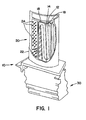
- a stylized turbine blade is illustrated in Figure 1, showing the general exterior configuration and, in the cutaway portion, some of the interior structure.
- the turbine rotor blade casting (10) is made up of two major portions, the blade (20) and the "Christmas tree" (30), which mates with one of a number corresponding shapes in a rotor disk, not shown, which receive a plurality of such blades in a annular ring to make up the turbine rotor.
- the exterior surfaces of the blade are structurally relatively simple, although the shapes are highly developed.
- the shape of the blade surfaces arc provided by the configuration of the interior of the waxing mold, with due allowances for shrinkage of the metal in the casting operation.
- the shape of the blade (20) is dictated by aerodynamic design parameters, while the shape of the "Christmas tree" (30) is dictated by the requirements of mounting the blade on its rotor disk.
- other shapes and configurations may be employed, including integral casting of the rotor disk with its appended blades, or the development a shape adapted to be welded to the surface of the rotor disk.
- the interior configuration is more complex, with serpentine air flow passages (12), provided with ribs (14) which serve to reinforce the metal blade structure and to control the turbulence and cooling effect of the air flow through the passages.
- the passages transport pressurized air through the blade from an inlet (16) from the central rotor disk to the exit ports (18) provided through the blade surface along the leading and trailing edges and at the blade tip.
- Thin wall sections of blade (20) adjacent the trailing edge (22) are supported by integrally cast posts (24), which provide structural reinforcing of the blade (20) and, the like the ribs (14), serve to influence the passing air flow. All these features must be provided in the casting by the blade core, as the interior of the casting is not accessible to machining operations after the casting is complete and the core is removed.
- the core has a highly complex and intricate form, necessary to provide the interior configuration of the turbine blade casting as described above. Indeed, every feature of the interior structure of the blade has a corresponding negative feature in the core, making the formation of the core to the precision and accuracy required a highly demanding aspect of the casting operation.
- the state of the art is not capable of such precise development of ceramic cores, and the limitations of the core forming operations are fed back into the engine design process to make allowances for these limitations.
- Common design allowances dictated by the variability of core manufacture are greater thickness of the wall sections of the blade, greater rib sizes than are required by structural demands, and enlarged diameter of supporting posts.
- the wall thickness employed must also make due allowances for the common levels of misalignments in the waxing mold.
- Figure 3 two conditions of alignment are shown in stylized cross-sections of molds and cores.
- Figure 3a shows a well aligned core (100) positioned within a mold (110), with substantially uniform spacing between the mold and core, which will in turn produce a hollow casting with substantially uniform wall thickness.
- Figure 3b illustrates the effect of a misaligned core (120) within a mold (130) wherein the core is twisted by two degrees relative to the mold. As shown the core misalignment produces a very thin spacing in some areas (140) and wider than designed spacing at other locations (150).
- the wall thickness will lack the intended uniformity, and will have thin portions which lack the designed structural properties, and other areas which are over-thick, and exceed the required structural characteristics and intended weight. It is common in the art to increase the design weight of the blade structure by ten to fifteen percent to accommodate such allowances.
- the procedure of making the turbine blades follows the normal sequence of investment casting techniques, with the introduction of the ultrasonic machining of the ceramic core structure after its firing and densification.
- the sequence of operations in the procedure includes the steps of:
Landscapes
- Engineering & Computer Science (AREA)
- Mechanical Engineering (AREA)
- Molds, Cores, And Manufacturing Methods Thereof (AREA)
- Powder Metallurgy (AREA)
- Mold Materials And Core Materials (AREA)
- Diaphragms For Electromechanical Transducers (AREA)
Claims (12)
- Procédé de production d'articles coulés à la cire perdue par coulage à la cire perdue avec un moule céramique (110), le procédé comprenant les étapes consistant à:A. façonner un moule céramique (110) en matériau céramique fritté;B. travailler au moins une partie sélectionnée (50, 100) dudit moule céramique fritté (110) par usinage à ultrason;C. verser un métal en fusion dans ledit moule (110);D. refroidir ledit métal en fusion en une pièce coulée solide; etE. retirer ledit moule (110) de ladite pièce coulée.
- Procédé selon la revendication 1, dans lequel au moins ladite partie sélectionnée (50, 100) dudit moule (110) est usinée par usinage à ultrason à une tolérance de ±0,2 mm.
- Procédé selon la revendication 1, dans lequel au moins ladite partie sélectionnée (50, 100) dudit moule (110) est usinée par usinage à ultrason à une tolérance de moins zéro, +0,05 mm.
- Procédé selon la revendication 1, dans lequel au moins ladite partie sélectionnée (50, 100) dudit moule (110) est usinée par usinage à ultrason à une tolérance de moins zéro, plus 0,02 mm.
- Procédé selon la revendication 1, dans lequel au moins ladite partie sélectionnée (50, 100) dudit moule (110) est usinée par usinage à ultrason par au moins une sonotrode d'usinage de forme présentant une superficie comprise entre environ 5 et environ 100 cm2.
- Procédé selon la revendication 1, dans lequel la partie sélectionnée du moule céramique fritté (110) comprend un noyau céramique (100).
- Procédé de production d'articles coulés à la cire perdue par coulage à la cire perdue avec un moule céramique (110), le procédé comprenant les étapes consistant à:A. façonner un noyau de moulage en matériau céramique cuit (100) presque à la forme utile et aux dimensions;B. mettre en forme ledit noyau céramique (100) à la forme utile et aux dimensions par usinage à ultrason;C. monter ledit noyau céramique usiné (100) dans un moule de modelage de cire;D. façonner une forme en cire à l'intérieur dudit moule de modelage de cire comprenant ledit noyau céramique (100);E. retirer ladite forme en cire dudit moule de modelage de cire;F. enduire ladite forme en cire d'une barbotine de façonnage de moule céramique;G. sécher ladite barbotine;H. chauffer ladite barbotine pour retirer ladite cire et pour densifier et cuire ladite barbotine céramique afin de façonner un moule de coulage à la cire perdue (110) comprenant ledit noyau céramique (100);I. verser un métal en fusion dans ledit moule de coulage (110);J. refroidir ledit métal en fusion en une pièce solide; etK. retirer ledit moule de coulage céramique (110) et ledit noyau céramique (100) dudit métal solide.
- Procédé selon la revendication 7, dans lequel au moins ledit noyau (100) dudit moule (110) est usiné par usinage à ultrason à une tolérance de ±0,2 mm.
- Procédé selon la revendication 7, dans lequel au moins ledit noyau (100) dudit moule (110) est usiné par usinage à ultrason à une tolérance de moins zéro, +0,05 mm.
- Procédé selon la revendication 7, dans lequel au moins ledit noyau (100) dudit moule (110) est usiné par usinage à ultrason à une tolérance de moins zéro, plus 0,02 mm.
- Procédé selon la revendication 7, dans lequel au moins ledit noyau (100) dudit moule (110) est usiné par usinage à ultrason par au moins une sonotrode d'usinage de forme présentant une superficie comprise entre environ 5 et environ 100 cm2.
- Procédé selon la revendication 1 ou 6, dans lequel le moule céramique (110) ou le noyau de moulage céramique (100) est façonné à partir d'une forme de modèle standard d'un matériau céramique fritté et au moins une de ses parties est travaillée par usinage à ultrason.
Applications Claiming Priority (3)
| Application Number | Priority Date | Filing Date | Title |
|---|---|---|---|
| US501511 | 1995-07-11 | ||
| US08/501,511 US5735335A (en) | 1995-07-11 | 1995-07-11 | Investment casting molds and cores |
| PCT/US1996/011412 WO1997002914A1 (fr) | 1995-07-11 | 1996-07-08 | Moules et noyaux de moule pour moulage a la cire perdue |
Publications (3)
| Publication Number | Publication Date |
|---|---|
| EP0877657A4 EP0877657A4 (fr) | 1998-11-18 |
| EP0877657A1 EP0877657A1 (fr) | 1998-11-18 |
| EP0877657B1 true EP0877657B1 (fr) | 2003-05-02 |
Family
ID=23993859
Family Applications (1)
| Application Number | Title | Priority Date | Filing Date |
|---|---|---|---|
| EP96924390A Expired - Lifetime EP0877657B1 (fr) | 1995-07-11 | 1996-07-08 | Moules et noyaux de moule pour moulage a la cire perdue |
Country Status (7)
| Country | Link |
|---|---|
| US (1) | US5735335A (fr) |
| EP (1) | EP0877657B1 (fr) |
| AT (1) | ATE238862T1 (fr) |
| AU (1) | AU714108B2 (fr) |
| CA (1) | CA2237390C (fr) |
| DE (1) | DE69627892T2 (fr) |
| WO (1) | WO1997002914A1 (fr) |
Families Citing this family (29)
| Publication number | Priority date | Publication date | Assignee | Title |
|---|---|---|---|---|
| US6467534B1 (en) * | 1997-10-06 | 2002-10-22 | General Electric Company | Reinforced ceramic shell molds, and related processes |
| US6347660B1 (en) | 1998-12-01 | 2002-02-19 | Howmet Research Corporation | Multipiece core assembly for cast airfoil |
| US6204149B1 (en) * | 1999-05-26 | 2001-03-20 | Micron Technology, Inc. | Methods of forming polished material and methods of forming isolation regions |
| US6505673B1 (en) * | 1999-12-28 | 2003-01-14 | General Electric Company | Method for forming a turbine engine component having enhanced heat transfer characteristics |
| US6533986B1 (en) | 2000-02-16 | 2003-03-18 | Howmet Research Corporation | Method and apparatus for making ceramic cores and other articles |
| US6505672B2 (en) * | 2001-05-22 | 2003-01-14 | Howmet Research Corporation | Fugitive patterns for investment casting |
| US6403020B1 (en) | 2001-08-07 | 2002-06-11 | Howmet Research Corporation | Method for firing ceramic cores |
| US6766850B2 (en) * | 2001-12-27 | 2004-07-27 | Caterpillar Inc | Pressure casting using a supported shell mold |
| US7500511B2 (en) * | 2003-09-24 | 2009-03-10 | Magneco/Metrel, Inc. | Molding composition and method of use |
| US7172012B1 (en) * | 2004-07-14 | 2007-02-06 | United Technologies Corporation | Investment casting |
| FR2878458B1 (fr) | 2004-11-26 | 2008-07-11 | Snecma Moteurs Sa | Procede de fabrication de noyaux ceramiques de fonderie pour aubes de turbomachines, outil pour la mise en oeuvre du procede |
| US20080000611A1 (en) * | 2006-06-28 | 2008-01-03 | Ronald Scott Bunker | Method for Forming Casting Molds |
| US8556681B2 (en) * | 2007-01-29 | 2013-10-15 | Tosoh Smd, Inc. | Ultra smooth face sputter targets and methods of producing same |
| US8016644B2 (en) * | 2007-07-13 | 2011-09-13 | UNIVERSITé LAVAL | Method and apparatus for micro-machining a surface |
| US8157527B2 (en) * | 2008-07-03 | 2012-04-17 | United Technologies Corporation | Airfoil with tapered radial cooling passage |
| US8572844B2 (en) * | 2008-08-29 | 2013-11-05 | United Technologies Corporation | Airfoil with leading edge cooling passage |
| US8303252B2 (en) * | 2008-10-16 | 2012-11-06 | United Technologies Corporation | Airfoil with cooling passage providing variable heat transfer rate |
| US8109725B2 (en) * | 2008-12-15 | 2012-02-07 | United Technologies Corporation | Airfoil with wrapped leading edge cooling passage |
| US8347947B2 (en) * | 2009-02-17 | 2013-01-08 | United Technologies Corporation | Process and refractory metal core for creating varying thickness microcircuits for turbine engine components |
| DE102010023644A1 (de) * | 2009-07-01 | 2011-01-05 | Ksm Castings Gmbh | Verfahren zum Gießen eines Materials, Verwendung des Verfahrens, Gießform zur Durchführung des Verfahrens und nach dem Verfahren bzw. in der Gießform hergestellte Gegenstände sowie Kern zum Einlegen in eine solche Gießform |
| FR2966067B1 (fr) * | 2010-10-19 | 2017-12-08 | Snecma | Moule d'injection pour modele en cire d'une aube de turbine a support du noyau isostatique |
| US8225841B1 (en) | 2011-01-03 | 2012-07-24 | James Avery Craftsman, Inc. | Central sprue for investment casting |
| US8424585B2 (en) | 2011-01-21 | 2013-04-23 | James Avery Craftsman, Inc. | Method and apparatus for creating a pattern |
| GB201608336D0 (en) | 2016-05-12 | 2016-06-29 | Rolls Royce Plc | A method of providing a fixture for a ceramic article, a method of machining a ceramic article and a method of investment casting using a ceramic article |
| FR3059259B1 (fr) | 2016-11-29 | 2019-05-10 | Jy'nove | Procede de fabrication d'un noyau ceramique de fonderie |
| CN107590315B (zh) * | 2017-08-15 | 2020-06-16 | 洛阳双瑞精铸钛业有限公司 | 一种非对称冒口的设计方法 |
| DE102017122973A1 (de) * | 2017-10-04 | 2019-04-04 | Flc Flowcastings Gmbh | Verfahren zur Herstellung eines keramischen Kerns für das Herstellen eines Gussteils mit Hohlraumstrukturen sowie keramischer Kern |
| CN114988852B (zh) * | 2022-05-13 | 2023-09-05 | 潍坊科技学院 | 一种具有多层夹层结构陶瓷型芯的制备方法 |
| CN115385674A (zh) * | 2022-09-22 | 2022-11-25 | 中国航发北京航空材料研究院 | 一种高精度陶瓷型芯的制备方法 |
Family Cites Families (6)
| Publication number | Priority date | Publication date | Assignee | Title |
|---|---|---|---|---|
| US5187899A (en) * | 1986-11-10 | 1993-02-23 | Extrude Hone Corporation | High frequency vibrational polishing |
| JPH01240224A (ja) * | 1988-03-17 | 1989-09-25 | Toshiba Corp | 吸引チャックの製造方法 |
| US5295530A (en) * | 1992-02-18 | 1994-03-22 | General Motors Corporation | Single-cast, high-temperature, thin wall structures and methods of making the same |
| US5296308A (en) * | 1992-08-10 | 1994-03-22 | Howmet Corporation | Investment casting using core with integral wall thickness control means |
| DE4332595A1 (de) * | 1993-09-24 | 1995-03-30 | Thera Ges Fuer Patente | Verfahren zur Herstellung von Sonotroden |
| US5465780A (en) * | 1993-11-23 | 1995-11-14 | Alliedsignal Inc. | Laser machining of ceramic cores |
-
1995
- 1995-07-11 US US08/501,511 patent/US5735335A/en not_active Expired - Lifetime
-
1996
- 1996-07-08 CA CA002237390A patent/CA2237390C/fr not_active Expired - Fee Related
- 1996-07-08 AT AT96924390T patent/ATE238862T1/de not_active IP Right Cessation
- 1996-07-08 AU AU64857/96A patent/AU714108B2/en not_active Ceased
- 1996-07-08 DE DE69627892T patent/DE69627892T2/de not_active Expired - Lifetime
- 1996-07-08 WO PCT/US1996/011412 patent/WO1997002914A1/fr not_active Ceased
- 1996-07-08 EP EP96924390A patent/EP0877657B1/fr not_active Expired - Lifetime
Also Published As
| Publication number | Publication date |
|---|---|
| CA2237390C (fr) | 2004-09-21 |
| DE69627892D1 (de) | 2003-06-05 |
| AU714108B2 (en) | 1999-12-16 |
| EP0877657A4 (fr) | 1998-11-18 |
| ATE238862T1 (de) | 2003-05-15 |
| US5735335A (en) | 1998-04-07 |
| AU6485796A (en) | 1997-02-10 |
| EP0877657A1 (fr) | 1998-11-18 |
| DE69627892T2 (de) | 2004-03-11 |
| CA2237390A1 (fr) | 1997-01-30 |
| WO1997002914A1 (fr) | 1997-01-30 |
Similar Documents
| Publication | Publication Date | Title |
|---|---|---|
| US5735335A (en) | Investment casting molds and cores | |
| US10357819B2 (en) | Investment casting of hollow components | |
| US5465780A (en) | Laser machining of ceramic cores | |
| US20200338630A1 (en) | Method for producing a ceramic core for the production of a casting having hollow structures and ceramic core | |
| US5904212A (en) | Gauge face inlay for bit hardfacing | |
| JP2003532539A (ja) | ネットニアシェイプ鋳型を製造するための方法 | |
| US7025108B2 (en) | Method for milling casting moulds | |
| US6386264B2 (en) | Method for machining sand block into sand molding elements including sand molds and sand cores for metal casting foundry operations | |
| US20040128016A1 (en) | Method for manufacturing a near net-shape mold | |
| CN111182982A (zh) | 用于制造陶瓷芯以制备具有空腔结构的铸件的方法以及陶瓷芯 | |
| US20030094730A1 (en) | Method and fabricating tools for earth boring | |
| JP2020514543A (ja) | タービン翼及びその先端部品の製造方法 | |
| RU2501639C2 (ru) | Способ удаления заусенцев с литейного стержня из керамического материала | |
| JP2008006502A (ja) | 鋳型の形成方法 | |
| WO1998023402A2 (fr) | Procede de production pour le coulage de forets a corps en acier | |
| US4579705A (en) | Process for producing ceramic products | |
| US6131677A (en) | Steel-bodied bit | |
| CN106695258A (zh) | 喷管腔面分段加工及抛光工艺 | |
| Denton et al. | QuickCast™ & rapid tooling: a case history at Ford Motor Company | |
| US11607721B2 (en) | Method for producing a model mold core blank and a precision casting mold, and a casting method for producing a cast part having a void structure | |
| McKeown | Ultra-precision diamond machining of advanced technology components | |
| JPS6234727A (ja) | フアインセラミツクスの複合加工法 |
Legal Events
| Date | Code | Title | Description |
|---|---|---|---|
| PUAI | Public reference made under article 153(3) epc to a published international application that has entered the european phase |
Free format text: ORIGINAL CODE: 0009012 |
|
| 17P | Request for examination filed |
Effective date: 19980505 |
|
| A4 | Supplementary search report drawn up and despatched |
Effective date: 19980928 |
|
| AK | Designated contracting states |
Kind code of ref document: A4 Designated state(s): AT CH DE FR GB IT LI NL PT SE Kind code of ref document: A1 Designated state(s): AT CH DE FR GB IT LI NL PT SE |
|
| 17Q | First examination report despatched |
Effective date: 20000620 |
|
| GRAG | Despatch of communication of intention to grant |
Free format text: ORIGINAL CODE: EPIDOS AGRA |
|
| GRAG | Despatch of communication of intention to grant |
Free format text: ORIGINAL CODE: EPIDOS AGRA |
|
| GRAG | Despatch of communication of intention to grant |
Free format text: ORIGINAL CODE: EPIDOS AGRA |
|
| GRAH | Despatch of communication of intention to grant a patent |
Free format text: ORIGINAL CODE: EPIDOS IGRA |
|
| GRAH | Despatch of communication of intention to grant a patent |
Free format text: ORIGINAL CODE: EPIDOS IGRA |
|
| GRAA | (expected) grant |
Free format text: ORIGINAL CODE: 0009210 |
|
| AK | Designated contracting states |
Designated state(s): AT CH DE FR GB IT LI NL PT SE |
|
| PG25 | Lapsed in a contracting state [announced via postgrant information from national office to epo] |
Ref country code: NL Free format text: LAPSE BECAUSE OF FAILURE TO SUBMIT A TRANSLATION OF THE DESCRIPTION OR TO PAY THE FEE WITHIN THE PRESCRIBED TIME-LIMIT Effective date: 20030502 Ref country code: LI Free format text: LAPSE BECAUSE OF FAILURE TO SUBMIT A TRANSLATION OF THE DESCRIPTION OR TO PAY THE FEE WITHIN THE PRESCRIBED TIME-LIMIT Effective date: 20030502 Ref country code: CH Free format text: LAPSE BECAUSE OF FAILURE TO SUBMIT A TRANSLATION OF THE DESCRIPTION OR TO PAY THE FEE WITHIN THE PRESCRIBED TIME-LIMIT Effective date: 20030502 Ref country code: AT Free format text: LAPSE BECAUSE OF FAILURE TO SUBMIT A TRANSLATION OF THE DESCRIPTION OR TO PAY THE FEE WITHIN THE PRESCRIBED TIME-LIMIT Effective date: 20030502 |
|
| REG | Reference to a national code |
Ref country code: GB Ref legal event code: FG4D |
|
| REG | Reference to a national code |
Ref country code: CH Ref legal event code: EP |
|
| REF | Corresponds to: |
Ref document number: 69627892 Country of ref document: DE Date of ref document: 20030605 Kind code of ref document: P |
|
| PG25 | Lapsed in a contracting state [announced via postgrant information from national office to epo] |
Ref country code: SE Free format text: LAPSE BECAUSE OF FAILURE TO SUBMIT A TRANSLATION OF THE DESCRIPTION OR TO PAY THE FEE WITHIN THE PRESCRIBED TIME-LIMIT Effective date: 20030802 |
|
| PG25 | Lapsed in a contracting state [announced via postgrant information from national office to epo] |
Ref country code: PT Free format text: LAPSE BECAUSE OF FAILURE TO SUBMIT A TRANSLATION OF THE DESCRIPTION OR TO PAY THE FEE WITHIN THE PRESCRIBED TIME-LIMIT Effective date: 20030804 |
|
| NLV1 | Nl: lapsed or annulled due to failure to fulfill the requirements of art. 29p and 29m of the patents act | ||
| REG | Reference to a national code |
Ref country code: CH Ref legal event code: PL |
|
| ET | Fr: translation filed | ||
| PLBE | No opposition filed within time limit |
Free format text: ORIGINAL CODE: 0009261 |
|
| STAA | Information on the status of an ep patent application or granted ep patent |
Free format text: STATUS: NO OPPOSITION FILED WITHIN TIME LIMIT |
|
| 26N | No opposition filed |
Effective date: 20040203 |
|
| REG | Reference to a national code |
Ref country code: GB Ref legal event code: 732E |
|
| REG | Reference to a national code |
Ref country code: FR Ref legal event code: TP |
|
| REG | Reference to a national code |
Ref country code: GB Ref legal event code: 732E |
|
| REG | Reference to a national code |
Ref country code: FR Ref legal event code: TP |
|
| PGFP | Annual fee paid to national office [announced via postgrant information from national office to epo] |
Ref country code: IT Payment date: 20070728 Year of fee payment: 12 |
|
| PG25 | Lapsed in a contracting state [announced via postgrant information from national office to epo] |
Ref country code: IT Free format text: LAPSE BECAUSE OF NON-PAYMENT OF DUE FEES Effective date: 20080708 |
|
| PGFP | Annual fee paid to national office [announced via postgrant information from national office to epo] |
Ref country code: FR Payment date: 20100805 Year of fee payment: 15 Ref country code: DE Payment date: 20100630 Year of fee payment: 15 |
|
| PGFP | Annual fee paid to national office [announced via postgrant information from national office to epo] |
Ref country code: GB Payment date: 20100707 Year of fee payment: 15 |
|
| GBPC | Gb: european patent ceased through non-payment of renewal fee |
Effective date: 20110708 |
|
| REG | Reference to a national code |
Ref country code: FR Ref legal event code: ST Effective date: 20120330 |
|
| PG25 | Lapsed in a contracting state [announced via postgrant information from national office to epo] |
Ref country code: DE Free format text: LAPSE BECAUSE OF NON-PAYMENT OF DUE FEES Effective date: 20120201 Ref country code: FR Free format text: LAPSE BECAUSE OF NON-PAYMENT OF DUE FEES Effective date: 20110801 |
|
| REG | Reference to a national code |
Ref country code: DE Ref legal event code: R119 Ref document number: 69627892 Country of ref document: DE Effective date: 20120201 |
|
| PG25 | Lapsed in a contracting state [announced via postgrant information from national office to epo] |
Ref country code: GB Free format text: LAPSE BECAUSE OF NON-PAYMENT OF DUE FEES Effective date: 20110708 |