EP0877690B1 - Servomoteur pneumatique d'assistance au freinage a clapet perfectionne - Google Patents
Servomoteur pneumatique d'assistance au freinage a clapet perfectionne Download PDFInfo
- Publication number
- EP0877690B1 EP0877690B1 EP96934910A EP96934910A EP0877690B1 EP 0877690 B1 EP0877690 B1 EP 0877690B1 EP 96934910 A EP96934910 A EP 96934910A EP 96934910 A EP96934910 A EP 96934910A EP 0877690 B1 EP0877690 B1 EP 0877690B1
- Authority
- EP
- European Patent Office
- Prior art keywords
- plunger
- piston
- chamber
- booster
- bore
- Prior art date
- Legal status (The legal status is an assumption and is not a legal conclusion. Google has not performed a legal analysis and makes no representation as to the accuracy of the status listed.)
- Expired - Lifetime
Links
- 238000004891 communication Methods 0.000 claims description 11
- 238000005192 partition Methods 0.000 claims description 4
- 230000004323 axial length Effects 0.000 claims description 3
- 239000007787 solid Substances 0.000 claims 2
- 239000012528 membrane Substances 0.000 description 5
- 230000002093 peripheral effect Effects 0.000 description 4
- 230000001965 increasing effect Effects 0.000 description 3
- 230000000694 effects Effects 0.000 description 2
- 239000011324 bead Substances 0.000 description 1
- 230000000295 complement effect Effects 0.000 description 1
- 230000006835 compression Effects 0.000 description 1
- 238000007906 compression Methods 0.000 description 1
- 230000003247 decreasing effect Effects 0.000 description 1
- 230000006866 deterioration Effects 0.000 description 1
- 229920001971 elastomer Polymers 0.000 description 1
- 239000000806 elastomer Substances 0.000 description 1
- 230000001939 inductive effect Effects 0.000 description 1
- 239000002184 metal Substances 0.000 description 1
- 238000000034 method Methods 0.000 description 1
- 238000012986 modification Methods 0.000 description 1
- 230000004048 modification Effects 0.000 description 1
- 238000007789 sealing Methods 0.000 description 1
Images


Classifications
-
- B—PERFORMING OPERATIONS; TRANSPORTING
- B60—VEHICLES IN GENERAL
- B60T—VEHICLE BRAKE CONTROL SYSTEMS OR PARTS THEREOF; BRAKE CONTROL SYSTEMS OR PARTS THEREOF, IN GENERAL; ARRANGEMENT OF BRAKING ELEMENTS ON VEHICLES IN GENERAL; PORTABLE DEVICES FOR PREVENTING UNWANTED MOVEMENT OF VEHICLES; VEHICLE MODIFICATIONS TO FACILITATE COOLING OF BRAKES
- B60T13/00—Transmitting braking action from initiating means to ultimate brake actuator with power assistance or drive; Brake systems incorporating such transmitting means, e.g. air-pressure brake systems
- B60T13/10—Transmitting braking action from initiating means to ultimate brake actuator with power assistance or drive; Brake systems incorporating such transmitting means, e.g. air-pressure brake systems with fluid assistance, drive, or release
- B60T13/24—Transmitting braking action from initiating means to ultimate brake actuator with power assistance or drive; Brake systems incorporating such transmitting means, e.g. air-pressure brake systems with fluid assistance, drive, or release the fluid being gaseous
- B60T13/46—Vacuum systems
- B60T13/52—Vacuum systems indirect, i.e. vacuum booster units
- B60T13/57—Vacuum systems indirect, i.e. vacuum booster units characterised by constructional features of control valves
-
- B—PERFORMING OPERATIONS; TRANSPORTING
- B60—VEHICLES IN GENERAL
- B60T—VEHICLE BRAKE CONTROL SYSTEMS OR PARTS THEREOF; BRAKE CONTROL SYSTEMS OR PARTS THEREOF, IN GENERAL; ARRANGEMENT OF BRAKING ELEMENTS ON VEHICLES IN GENERAL; PORTABLE DEVICES FOR PREVENTING UNWANTED MOVEMENT OF VEHICLES; VEHICLE MODIFICATIONS TO FACILITATE COOLING OF BRAKES
- B60T13/00—Transmitting braking action from initiating means to ultimate brake actuator with power assistance or drive; Brake systems incorporating such transmitting means, e.g. air-pressure brake systems
- B60T13/10—Transmitting braking action from initiating means to ultimate brake actuator with power assistance or drive; Brake systems incorporating such transmitting means, e.g. air-pressure brake systems with fluid assistance, drive, or release
- B60T13/24—Transmitting braking action from initiating means to ultimate brake actuator with power assistance or drive; Brake systems incorporating such transmitting means, e.g. air-pressure brake systems with fluid assistance, drive, or release the fluid being gaseous
- B60T13/241—Differential pressure systems
- B60T13/246—The control valve is provided apart from the servomotor cylinder
- B60T13/248—Mechanical command of the control valve, hydraulic transmission to the brakes
Definitions
- the present invention relates to pneumatic actuators, of the type which are used to provide brake assist for motor vehicles.
- Such servomotors are well known in the automotive technique and include conventionally an envelope inside which is a piston formed by a hub and a skirt.
- the piston defines a front chamber permanently connected to a bass source pressure and a rear chamber selectively connected to the front chamber or to a source of high pressure by means of valve.
- This valve means is actuated by a control rod likely to rest, via the front face of a diver, on the face rear of a reaction disc secured to a push rod, the latter actuating a master cylinder.
- the valve means usually comprises a valve whose annular front face cooperates with a first circular valve seat formed on the plunger and a second seat circular valve formed on the piston and of diameter greater than that of the first seat of valve.
- a valve spring biases the annular front face in the direction of the valve seats. so that the latter is always in contact with at least one of these two seats.
- Such servomotors have several drawbacks. This is how, to ensure the closure of the communication between the front and rear chambers of the front actuator the opening of the communication between the rear chamber and the high pressure source, we are forced to make the plunger and the piston hub with very strict tolerances to avoid that the control rod does not have a too long dead travel, is still to design the valve means such that the "valve lift" between the valve and the first seat of valve is as low as possible.
- An additional disadvantage of the known servomotors lies in the fact that the only radial passage offered to high pressure air to the rear chamber during actuation, as well as the only axial passage offered to the air from the rear chamber to the front chamber during of a brake release cause turbulence in the moving air, slowing the action of the servomotor and inducing operating noise which can become annoying.
- valve being formed of a flexible membrane fixed in a sealed manner by its peripheral edge outside the piston by means of a metal cup also serving support for the valve spring and for a return spring of the control rod, mounting three-way valve means in the piston hub is a delicate operation and complex, the scrap rate of which is not negligible and which contributes to increase appreciably the cost price of the servomotor.
- Document DE-A-3 445 118 attempts to provide a solution to these problems, by providing to make the plunger like a dispenser drawer.
- the diver is likely slide in a bore in the piston hub to obscure or uncover two lights formed in the hub and communicating with the rear chamber of the actuator.
- Such a design still requires a very precise adjustment between the hub bore of the piston and the plunger sliding therein. It also requires the presence of a seal sealing at the edges of one of the openings formed in the piston hub and of a seal seal at the end of the plunger. These seals cooperate either with an edge of the plunger, either with the edge of one of the lights, and they are therefore subject to very rapid deterioration, which affects the reliability of the servomotor thus equipped.
- this document does not yet provide only one axial passage between the front and rear chambers, and a single radial passage between the high pressure source and the rear chamber, again resulting in generating turbulence operating noises and a slowing down of the action of the servomotor.
- the present invention is placed in this context and aims to provide a motor in which the air passages between the atmosphere and the rear chamber on the one hand, the rear chamber and the front chamber on the other hand, have the largest possible section without presenting obstacles that can cause turbulence in order to obtain an operation silent and as short a response time as possible, in a simple, reliable and economical way.
- the present invention provides a pneumatic booster for assisting the braking, comprising an envelope having an axis of symmetry, separated in a sealed manner by at least one movable wall structure in at least one permanently connected front chamber to a low pressure source, and at least one rear chamber selectively connected to the front chamber or to a high pressure source by a three-way valve means comprising a plunger sliding in a bore of a piston and integral with a control rod, the position of the plunger in the bore determining the communication between the front chambers and rear or communication between the rear chamber and the high pressure source.
- a support structure is arranged in the piston, this support structure comprising two annular seals cooperating with a cylindrical surface of the plunger and a central sliding guide portion of the plunger.
- the annular seals are each formed at an angle whose vertex at rest is located at a distance from the axis of symmetry slightly less than the radius of the cylindrical surface of the plunger.
- angles of the joints are located in parallel planes axially spaced a distance slightly less than the axial length of the surface cylindrical of the plunger.
- the cylindrical surface of the plunger is connected at the front and rear to frustoconical surfaces.
- openings are formed in the middle part of the support structure and communicate with radial passages formed in the piston and communicating with the rear chamber of the actuator.
- the piston may then include axial passages opening into the bore in which the plunger slides and communicating with the front chamber of the actuator, these axial passages being aligned with the passages radials communicating with the rear chamber of the actuator.
- the three-way valve is arranged in a tubular part rear of the piston secured to the movable wall structure of the booster.
- the three-way valve is arranged in a piston a control module controlling the servomotor remotely.
- a control module may advantageously include a stepped piston dividing a bore into a first volume permanently connected to the rear chamber of the actuator by a pipe, in a second volume permanently connected to the front chamber of the booster by a pipe, and in one annular assistance chamber connected by a pipe to the outlet of a pressure transmitter actuated by the servomotor
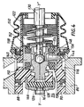
- Figure 1 shows a sectional view of a pneumatic booster to assist braking intended to be placed in a conventional manner between the brake pedal of a vehicle and the master cylinder controlling the pressure in the hydraulic braking circuit of this vehicle.
- the part of the servomotor facing “forward” is called the master cylinder and “rear” of the servomotor the part facing the brake pedal.
- the front is thus on the left and the rear on the right.
- the actuator shown in Figures 1 and 2 comprises an outer casing 10 shell-shaped, having a symmetry of revolution about an axis XX '. Only the rear central part of this envelope 10 is shown in FIG. 2.
- a movable wall structure 12 delimits inside the envelope 10 a chamber front 14, permanently connected to a vacuum source by a pipe 15, and a rear chamber 16.
- the movable wall 12 is associated with a flexible unrolling membrane in elastomer, the inner peripheral edge of which is tightly received by means of a bead 18 in a hollow assistance piston 20, integral with the movable wall structure 12, and disposed along the axis XX 'of the servomotor, the outer peripheral edge of the flexible membrane being tightly fixed on the outer casing 10.
- the hollow piston 20 extends backwards in the form of a tubular part 22 which tightly crosses the rear wall of the casing 10.
- a compression spring 24 interposed between the piston 20 and the front wall of the casing 10 normally holds the piston 20 in the rear rest position illustrated in FIGS. 1 and 2, in which the chamber rear 16 has its minimum volume and the front chamber 14 its maximum volume.
- a plunger 28, symmetrical with respect to the axis XX ′, is slidably received by its front end in a bore 26, possibly stepped, formed in the central part of the piston 20.
- the front end of a control rod 30 of the servomotor, also arranged along the axis XX ', is pivotally mounted in a blind bore of the plunger 28.
- the rear end of the control rod 30 is controlled directly by the vehicle brake pedal (not shown), and is returned to its rest position by a return spring 31 bearing inside the tubular part 22.
- the control rod 30 actuates a three-way valve means for communicating the annular space 32 around the control rod 30 with the rear chamber 16, and thus create a pressure difference on either side of the movable wall 12, resulting in a assistance force proportional to the force exerted on the brake pedal.
- the three-way valve means consists of the plunger 28 itself.
- the plunger 28 is formed with a cylindrical outer surface 34 in which a peripheral groove 36 defines two radial shoulders.
- the surface 34 is connected at the front to a frustoconical surface 35, and to the rear to a frustoconical surface 37.
- a support structure 38 is fixedly arranged in the tubular part 22 and has a middle portion 40 between two annular housings 42 and 44 for annular seals 46 and 48 respectively.
- the inside diameter of the middle part 40 is slightly greater than the diameter of the cylindrical surface 34, so as to provide guidance for the plunger in its translational movements along the axis XX '.
- the annular seals 46 and 48 are identical and have a cross section of polygonal shape, the outer part of which (relative to the axis XX ') is complementary to that of the housings 42 and 44.
- the interior part of the section of each joint is triangular, and forms a salient angle 50 and 52 respectively, the apex of which, at rest, is located at a distance from axis XX 'slightly less than the radius of the cylindrical surface 34 of the plunger 28.
- angles 50 and 52 are located in axially distant parallel planes by a distance D, and the axial length L of the cylindrical surface 34 of the plunger 28 is slightly greater than distance D.
- the support structure 38 In its middle part 40, the support structure 38 has radial openings 54, regularly distributed around the axis XX ′, communicating with radial passages 56 formed in the tubular part 22 of the piston 20 and opening into the rear chamber 16 of the servo motor.
- the piston 20 is also formed with axial passages 58, regularly distributed around the axis XX ', and communicating the front chamber 14 of the booster with the front part 60 of the internal volume of the bore 26 around the plunger 28, in front of the surface frustoconical 35.
- At least one stop member 62 is mounted in the tubular part 22 of the piston 20 to delimit the axial stroke of the plunger 28 relative to the piston 20 and define its position rear rest relative to the latter.
- the stop member 62 crosses, for example, the openings 52 and the passages 54 to form a support on the rear face of the front shoulder of the throat 36 of the plunger 28.
- the driver of the vehicle depresses the brake pedal. brake, which results in a forward movement of the control rod 30 and the plunger 28.
- the latter slides first in the bore 26 and in the guide surface formed by the middle part 40 of the support structure 38.
- the openings 54 and the passages 56 so that they extend over arcs of a circle of angular extent relatively important, since the seals 46 and 48 as well as the support structure 38 do not are subjected to relatively low stresses, and therefore do not need to have resistance very high mechanical. We can therefore make the most of the opening on 360 degrees of the valve passage formed by the annular seal 48 cooperating with the surface 34 of the diver.
- valve passages between the atmosphere and the rear chamber on the one hand, and between the rear chamber and the front chamber on the other hand, are located in different transverse planes, containing angles 50 and 52, and are no longer coplanar as in the conventional design of the prior art. It follows that the diameter of these passages valves are independent of each other, and are only limited by the maximum diameter of the tubular part 22 or by the minimum diameter of the plunger 28. We can therefore give these valve passages any desired diameter between these two limits.
- a rapid rebalancing of pressures (in this case of depression) between the two chambers 14 and 16, is obtained by authorizing a relatively large recoil of the plunger 28 relative to the piston 20. It is therefore seen here again that the air is caused to flow through the passages 58, the angular extent of which can be relatively large.
- valve 34-50 is only limited by the maximum diameter of the tubular part 22 or by the diameter minimum of the diver 28. We can therefore give it any desired value.
- the invention also makes it possible to significantly reduce the noise of servomotor operation.
- the special design of the three-way valve constituting the valve according to the invention makes it possible to provide that the openings or passages 54, 56 and 58 are in equal number, regularly distributed around the axis XX ', and so that their centers are in the same plane, as shown in Figure 2. In this way, the air masses put in motion during operation of the servomotor fitted with the valve according to this invention will have a speed whose components will only be contained in one plane, for example of Figure 2.
- the air flow in the actuator is perfectly symmetrical around the axis X-X 'in all operating cases, i.e. all turbulence are eliminated, as well as the resulting noises.
- FIGS. 3 and 4 show a second embodiment of the present invention, applicable to a control module 100 of a servomotor of the type which is described for example in document EP-A-0 326 965.
- the elements corresponding to those of Figures 1 and 2 are assigned the same reference numbers, increased of a hundred.
- the control module 100 is actuated by a control rod 130 connected to a brake pedal (not shown) located in the passenger compartment of the vehicle.
- Module 100 includes a body 86 having a symmetry of revolution about an axis Y-Y 'and formed with a bore stepped 88 in which slides in step a stepped piston 90.
- the piston 90 divides internally the bore 88 in a first volume 116 formed at the rear of the bore and a second volume 114 formed at the front, and permanently connected to a source of vacuum by a pipe 115.
- the piston 90 is extended towards the rear by a rear tubular part 122 sliding tightly in the body 86, and it is formed with a bore 126, possibly stepped, in which slides a plunger 128.
- the first volume 116 is selectively put in communication with the second volume 114 or with the annular space 132 around the control rod 130 where reigns for example atmospheric pressure, by a three-way valve conforming to that which has been described in relation with Figures 1 and 2, disposed in a housing of the piston 90, and actuated by a plunger 128 integral with the control rod 130 and symmetrical with respect to the axis Y-Y 'of the module 100.
- a first valve passage has a seal 148 cooperating with the cylindrical surface 134 of the plunger 128, and the second valve passage comprises a seal 146 cooperating with this same surface 134.
- a support structure 138 identical to the structure 38 described above plays the same role of guiding the plunger 128 and housing the seals 146 and 148, and will therefore not be described more in detail.
- the piston 90 is also formed with axial passages 158, regularly distributed around the axis Y-Y ', and making the second volume 114 of the control module communicate 100 with the volume 160 around the plunger 128, and a stop member 162 is mounted in the piston 90 to delimit the axial stroke of the plunger 128 relative to the piston 90 and define its rear position of rest relative to the latter.
- control module 100 is intended to remotely control a servomotor 300, shown diagrammatically, formed of an envelope internally divided by a mobile watertight partition into a permanently connected front chamber to the second volume 114 by the pipe 115, and a rear chamber permanently connected to the first volume 116 by a pipe 117.
- a servomotor 300 shown diagrammatically, formed of an envelope internally divided by a mobile watertight partition into a permanently connected front chamber to the second volume 114 by the pipe 115, and a rear chamber permanently connected to the first volume 116 by a pipe 117.
- a pressure transmitter such as a single master cylinder 400 is attached to the front wall of the servomotor 300 and is actuated by this servomotor.
- the output of this pressure transmitter 400 is connected by a hydraulic pipe 119 to an annular assistance chamber 92 formed in the body 86 of the control module 100 between the shoulders of the stepped bore 88 and the stepped piston 90.
- the control rod 130 moves forward. Diver 128 then controls the operation the three-way valve as described above so that it isolates everything first volumes 114 and 116 from each other, then connects the first volume 116 with the annular space 132. This results in an increase in pressure in the volume 116, transmitted via line 117 to the rear chamber of the servomotor 300, including the chamber front is permanently connected to the vacuum source.
- This pressure difference is exerted on the two faces of the movable partition of the actuator 300 and tends to move it forward so that it moves the piston of the transmitter pressure 400 and causes an increase in pressure in line 119, transmitted to the annular assistance chamber 92.
- the pressure in the annular chamber 92 is exerted on the shoulder of the piston 90 and tends thus to advance it.
- the piston 90 has an annular face surrounding the front face of the plunger 128, these two faces being supported on a reaction disc 166 secured to a rod 164.
- the reaction disc 166 therefore simultaneously receives the input force transmitted by the plunger 128 and the assistance force transmitted by the piston 90 on which the pressure is exerted in chamber 92.
- the reaction disc 166 and the push rod 164 transmit the sum of these two efforts to the piston 94 of a master cylinder 200, which then generates an increase pressure in the brake motors (not shown), which causes the action of assisted braking required by the driver of the vehicle.
- the axial passages and the openings radial formed in the support structure 138, and the radial passages formed in the piston 90 are aligned in the axial direction and extend over arcs of a circle with the same angle in the center, so as to give them relatively large angular expanses, these different elements being only subjected to relatively low efforts, and therefore not needing to have a very high mechanical resistance.
- the two valve passages, between the atmosphere and the rear volume 116 on the one hand, and between the rear volumes 116 and front 114 on the other hand, are located in different transverse planes, and their diameters are independent of each other. We will be able to still give them predetermined dimensions, resulting in an air passage section predetermined.
- the pressure can thus increase relatively quickly in the rear volume 116 of the control module 100, and therefore in the rear chamber of the servomotor 300, and create a difference in pressures on the movable wall, resulting in increasing hydraulic pressure quickly in the assistance chamber 92 to move the piston 90 forwards.
- the operating noise of the control module is also reduced in significant proportions.
- the particular design of the three ways constituting the valve according to the invention allows to provide that the different openings air passages are equal in number, regularly distributed around the axis Y-Y ', and so that their centers are in the same plane, as seen in Figure 4. From the sort, the air masses set in motion during the operation of the control module equipped with the valve of the present invention will have a speed whose components will not contained only in a plane, for example that of Figure 4.
- the air flow in the control module is perfectly symmetrical around the axis Y-Y ', in all operating cases, i.e. all turbulence is eliminated, as well as the resulting noise.
Landscapes
- Engineering & Computer Science (AREA)
- Transportation (AREA)
- Mechanical Engineering (AREA)
- Braking Systems And Boosters (AREA)
Description
- La Figure 1 représente une vue de côté, en coupe longitudinale, d'un servomoteur pneumatique d'assistance au freinage, équipé d'un clapet réalisé conformément à la présente invention;
- La Figure 2 représente une vue à plus grande échelle de la partie centrale arrière du servomoteur de la Figure 1;
- La Figure 3 représente une vue de côté, en coupe longitudinale, d'un module de commande d'un servomoteur pneumatique d'assistance au freinage, ce module étant équipé d'un clapet réalisé conformément à la présente invention; et
- La Figure 4 représente une vue à plus grande échelle de la partie centrale arrière du module de commande de la Figure 3.
Claims (9)
- Servomoteur pneumatique d'assistance au freinage, comportant une enveloppe (10) possédant un axe de symétrie (X-X'), séparée de façon étanche par au moins une structure de paroi mobile (12) en au moins une chambre avant (14) reliée en permanence à une source de basse pression, et au moins une chambre arrière (16) reliée sélectivement à la chambre avant (14) ou à une source de haute pression par un moyen de valve à trois voies comportant un plongeur (28, 128) coulissant dans un alésage (26, 126) d'un piston (20, 90) et solidaire d'une tige de commande (30, 130), la position du plongeur (28, 128) dans l'alésage (26, 126) déterminant la communication entre les chambres avant (14) et arrière (16) ou la communication entre la chambre arrière (16) et la source de haute pression, caractérisé en ce qu'une structure de support (38, 138) est disposée dans le piston (20, 90), cette structure de support (38, 138) comportant deux joints annulaires (46, 48; 146, 148) coopérant avec une surface cylindrique (34, 134) du plongeur (28, 128) et une partie médiane (40, 140) de guidage en coulissement du plongeur (28, 128).
- Servomoteur pneumatique selon la revendication 1, caractérisé en ce que les joints annulaires (46, 48; 146, 148) sont formés chacun avec un angle (50, 52; 150, 152) dont le sommet au repos est situé à une distance de l'axe de symétrie (X-X') légèrement inférieure au rayon de la surface cylindrique (34, 134) du plongeur (28, 128).
- Servomoteur pneumatique selon la revendication 2, caractérisé en ce que les angles (50, 52; 150, 152) des joints (46, 48; 146, 148) sont situés dans des plans parallèles éloignés axialement d'une distance (D) légèrement inférieure à la longueur axiale (L) de la surface cylindrique (34, 134) du plongeur (28, 128).
- Servomoteur pneumatique selon la revendication 3, caractérisé en ce que la surface cylindrique (34, 134) du plongeur (28, 128) est raccordée à l'avant et à l'arrière à des surfaces tronconiques (35, 37; 135, 137).
- Servomoteur pneumatique selon la revendication 4, caractérisé en ce que des ouvertures (54, 154) sont formées dans la partie médiane (40, 140) de la structure de support (38, 138) et communiquent avec des passages radiaux (56, 156) formés dans le piston (20, 90) et communiquant avec la chambre arrière du servomoteur.
- Servomoteur pneumatique selon la revendication 5, caractérisé en ce que le piston (20, 90) comporte des passages axiaux (58, 158) débouchant dans l'alésage dans lequel coulisse le plongeur (28, 128) et communiquant avec la chambre avant du servomoteur, ces passages axiaux (58, 158) étant alignés avec les passages radiaux (56, 156) communiquant avec la chambre arrière du servomoteur.
- Servomoteur pneumatique selon l'une quelconque des revendications précédentes, caractérisé en ce que la valve à trois voies est disposée dans une partie tubulaire arrière (22) du piston (20) solidaire de la structure de paroi mobile (12) du servomoteur.
- Servomoteur pneumatique selon l'une quelconque des revendications 1 à 6, caractérisé en ce que la valve à trois voies est disposée dans un piston (90) d'un module de commande (100) pilotant à distance le servomoteur.
- Servomoteur pneumatique selon la revendication 8, caractérisé en ce que le module de commande (100) comporte un piston étagé (90) divisant un alésage (88) en un premier volume (116) relié en permanence à la chambre arrière du servomoteur (300) par une canalisation (117), en un second volume (114) relié en permanence à la chambre avant du servomoteur (300) par une canalisation (115), et en une chambre annulaire d'assistance (92) reliée par une canalisation (119) à la sortie d'un émetteur de pression (400) actionné par le servomoteur.
Applications Claiming Priority (3)
| Application Number | Priority Date | Filing Date | Title |
|---|---|---|---|
| FR9601043 | 1996-01-30 | ||
| FR9601043A FR2744085B1 (fr) | 1996-01-30 | 1996-01-30 | Servomoteur pneumatique d'assistance au freinage a clapet perfectionne |
| PCT/FR1996/001604 WO1997028033A1 (fr) | 1996-01-30 | 1996-10-15 | Servomoteur pneumatique d'assistance au freinage a clapet perfectionne |
Publications (2)
| Publication Number | Publication Date |
|---|---|
| EP0877690A1 EP0877690A1 (fr) | 1998-11-18 |
| EP0877690B1 true EP0877690B1 (fr) | 2001-12-19 |
Family
ID=9488597
Family Applications (1)
| Application Number | Title | Priority Date | Filing Date |
|---|---|---|---|
| EP96934910A Expired - Lifetime EP0877690B1 (fr) | 1996-01-30 | 1996-10-15 | Servomoteur pneumatique d'assistance au freinage a clapet perfectionne |
Country Status (7)
| Country | Link |
|---|---|
| US (1) | US5878577A (fr) |
| EP (1) | EP0877690B1 (fr) |
| JP (1) | JP2000502970A (fr) |
| DE (1) | DE69618243T2 (fr) |
| ES (1) | ES2167607T3 (fr) |
| FR (1) | FR2744085B1 (fr) |
| WO (1) | WO1997028033A1 (fr) |
Families Citing this family (4)
| Publication number | Priority date | Publication date | Assignee | Title |
|---|---|---|---|---|
| DE19805841A1 (de) * | 1998-02-13 | 1999-08-19 | Itt Mfg Enterprises Inc | Bremskraftverstärker für Kraftfahrzeuge |
| US6513311B1 (en) * | 2002-01-02 | 2003-02-04 | New Holland North America, Inc. | Automatic configuration of dual cutter mode windrowers |
| FR2839489B1 (fr) | 2002-05-07 | 2004-11-12 | Bosch Gmbh Robert | Dispositif de fusible pour servomoteur pneumatique d'assistance au freinage |
| DE102015211288B4 (de) * | 2015-06-18 | 2025-11-27 | Continental Automotive Technologies GmbH | Pneumatischer Bremskraftverstärker mit einem Steuergehäuse |
Family Cites Families (11)
| Publication number | Priority date | Publication date | Assignee | Title |
|---|---|---|---|---|
| US1797853A (en) * | 1923-12-22 | 1931-03-24 | Bragg Kliesrath Corp | Power actuator |
| US3037487A (en) * | 1960-11-28 | 1962-06-05 | Gen Motors Corp | Brake booster valve means |
| DE1427005A1 (de) * | 1961-10-23 | 1971-03-04 | Alois Mossmann | Vorrichtung zur selbsttaetigen Einstellung oder Begrenzung der Schlittenwege von Werkzeugmaschinen |
| DE1938971A1 (de) * | 1969-07-31 | 1971-02-18 | Bosch Gmbh Robert | Bremsverstaerker |
| DE3445118A1 (de) * | 1984-12-11 | 1986-06-12 | Alfred Teves Gmbh, 6000 Frankfurt | Vakuumbremskraftverstaerker |
| FR2638691B1 (fr) * | 1988-11-10 | 1994-05-13 | Bendix France Sa | Systeme de freinage hydraulique assiste, et servomoteur d'assistance et valve de commande adaptes a un tel systeme |
| US4894068A (en) * | 1988-12-27 | 1990-01-16 | Permea, Inc. | Process for capturing nitrogen from air using gas separation membranes |
| US5102432A (en) * | 1990-12-10 | 1992-04-07 | Union Carbide Industrial Gases Technology Corporation | Three-stage membrane gas separation process and system |
| US5233837A (en) * | 1992-09-03 | 1993-08-10 | Enerfex, Inc. | Process and apparatus for producing liquid carbon dioxide |
| CA2101804A1 (fr) * | 1992-10-06 | 1994-04-07 | Christian Friedrich Gottzmann | Procede d'ultrafiltration multi-etage par membranes |
| JP3491056B2 (ja) * | 1993-09-20 | 2004-01-26 | トキコ株式会社 | 気圧式倍力装置 |
-
1996
- 1996-01-30 FR FR9601043A patent/FR2744085B1/fr not_active Expired - Fee Related
- 1996-10-15 US US08/737,030 patent/US5878577A/en not_active Expired - Lifetime
- 1996-10-15 EP EP96934910A patent/EP0877690B1/fr not_active Expired - Lifetime
- 1996-10-15 JP JP9516883A patent/JP2000502970A/ja not_active Ceased
- 1996-10-15 WO PCT/FR1996/001604 patent/WO1997028033A1/fr not_active Ceased
- 1996-10-15 DE DE69618243T patent/DE69618243T2/de not_active Expired - Lifetime
- 1996-10-15 ES ES96934910T patent/ES2167607T3/es not_active Expired - Lifetime
Also Published As
| Publication number | Publication date |
|---|---|
| DE69618243T2 (de) | 2002-08-08 |
| EP0877690A1 (fr) | 1998-11-18 |
| FR2744085B1 (fr) | 1998-08-14 |
| US5878577A (en) | 1999-03-09 |
| JP2000502970A (ja) | 2000-03-14 |
| ES2167607T3 (es) | 2002-05-16 |
| WO1997028033A1 (fr) | 1997-08-07 |
| FR2744085A1 (fr) | 1997-08-01 |
| DE69618243D1 (de) | 2002-01-31 |
Similar Documents
| Publication | Publication Date | Title |
|---|---|---|
| EP0509866B1 (fr) | Servomoteur pneumatique | |
| EP0662894B1 (fr) | Dispositif de freinage assiste a reaction hydraulique ralentie | |
| FR2751602A1 (fr) | Dispositif de freinage assiste a rapport d'assistance variable | |
| EP0659134B1 (fr) | Servomoteur pneumatique | |
| EP0613431B1 (fr) | Servomoteur pneumatique | |
| EP0779870B1 (fr) | Servomoteur pneumatique d'assistance au freinage | |
| EP0514239B1 (fr) | Servomoteur pneumatique | |
| EP0509867B1 (fr) | Servomoteur pneumatique | |
| EP0877691B1 (fr) | Servomoteur pneumatique d'assistance au freinage a clapet perfectionne | |
| FR2744085A1 (fr) | Servomoteur pneumatique d'assistance au freinage a clapet perfectionne | |
| EP0802868B1 (fr) | Dispositif de freinage assiste a course reduite | |
| EP0877689B1 (fr) | Servomoteur pneumatique d'assistance au freinage a clapet perfectionne | |
| EP0509868B1 (fr) | Servomoteur pneumatique | |
| EP0738219B1 (fr) | Servomoteur pneumatique d'assistance au freinage, a fonctionnement silencieux | |
| EP0514224A1 (fr) | Servomoteur pneumatique | |
| EP0991556B1 (fr) | Servomoteur pneumatique d'assistance au freinage a clapet perfectionne | |
| WO1995014597A1 (fr) | Dispositif de freinage assiste a course masquee et a gain garanti | |
| EP0368701B1 (fr) | Système de freinage hydraulique assisté, et servomoteur d'assistance et valve de commande adaptes a un tel système | |
| EP0702637B1 (fr) | Servomoteur pneumatique | |
| WO1996022210A1 (fr) | Servomoteur pneumatique d'assistance au freinage a clapet souple |
Legal Events
| Date | Code | Title | Description |
|---|---|---|---|
| PUAI | Public reference made under article 153(3) epc to a published international application that has entered the european phase |
Free format text: ORIGINAL CODE: 0009012 |
|
| 17P | Request for examination filed |
Effective date: 19971210 |
|
| AK | Designated contracting states |
Kind code of ref document: A1 Designated state(s): DE ES FR GB IT |
|
| GRAG | Despatch of communication of intention to grant |
Free format text: ORIGINAL CODE: EPIDOS AGRA |
|
| 17Q | First examination report despatched |
Effective date: 20010404 |
|
| GRAG | Despatch of communication of intention to grant |
Free format text: ORIGINAL CODE: EPIDOS AGRA |
|
| GRAH | Despatch of communication of intention to grant a patent |
Free format text: ORIGINAL CODE: EPIDOS IGRA |
|
| GRAH | Despatch of communication of intention to grant a patent |
Free format text: ORIGINAL CODE: EPIDOS IGRA |
|
| GRAA | (expected) grant |
Free format text: ORIGINAL CODE: 0009210 |
|
| AK | Designated contracting states |
Kind code of ref document: B1 Designated state(s): DE ES FR GB IT |
|
| REG | Reference to a national code |
Ref country code: GB Ref legal event code: IF02 |
|
| REF | Corresponds to: |
Ref document number: 69618243 Country of ref document: DE Date of ref document: 20020131 |
|
| GBT | Gb: translation of ep patent filed (gb section 77(6)(a)/1977) |
Effective date: 20020325 |
|
| REG | Reference to a national code |
Ref country code: ES Ref legal event code: FG2A Ref document number: 2167607 Country of ref document: ES Kind code of ref document: T3 |
|
| PLBE | No opposition filed within time limit |
Free format text: ORIGINAL CODE: 0009261 |
|
| STAA | Information on the status of an ep patent application or granted ep patent |
Free format text: STATUS: NO OPPOSITION FILED WITHIN TIME LIMIT |
|
| 26N | No opposition filed | ||
| PGFP | Annual fee paid to national office [announced via postgrant information from national office to epo] |
Ref country code: GB Payment date: 20131022 Year of fee payment: 18 Ref country code: FR Payment date: 20131018 Year of fee payment: 18 |
|
| PGFP | Annual fee paid to national office [announced via postgrant information from national office to epo] |
Ref country code: ES Payment date: 20131022 Year of fee payment: 18 Ref country code: IT Payment date: 20131030 Year of fee payment: 18 |
|
| PGFP | Annual fee paid to national office [announced via postgrant information from national office to epo] |
Ref country code: DE Payment date: 20131217 Year of fee payment: 18 |
|
| REG | Reference to a national code |
Ref country code: DE Ref legal event code: R119 Ref document number: 69618243 Country of ref document: DE |
|
| GBPC | Gb: european patent ceased through non-payment of renewal fee |
Effective date: 20141015 |
|
| PG25 | Lapsed in a contracting state [announced via postgrant information from national office to epo] |
Ref country code: GB Free format text: LAPSE BECAUSE OF NON-PAYMENT OF DUE FEES Effective date: 20141015 Ref country code: DE Free format text: LAPSE BECAUSE OF NON-PAYMENT OF DUE FEES Effective date: 20150501 |
|
| REG | Reference to a national code |
Ref country code: FR Ref legal event code: ST Effective date: 20150630 |
|
| PG25 | Lapsed in a contracting state [announced via postgrant information from national office to epo] |
Ref country code: IT Free format text: LAPSE BECAUSE OF NON-PAYMENT OF DUE FEES Effective date: 20141015 Ref country code: FR Free format text: LAPSE BECAUSE OF NON-PAYMENT OF DUE FEES Effective date: 20141031 |
|
| REG | Reference to a national code |
Ref country code: ES Ref legal event code: FD2A Effective date: 20151127 |
|
| PG25 | Lapsed in a contracting state [announced via postgrant information from national office to epo] |
Ref country code: ES Free format text: LAPSE BECAUSE OF NON-PAYMENT OF DUE FEES Effective date: 20141016 |