EP0877708B1 - Verfahren und vorrichtung zum etikettieren von behältern - Google Patents
Verfahren und vorrichtung zum etikettieren von behältern Download PDFInfo
- Publication number
- EP0877708B1 EP0877708B1 EP97947385A EP97947385A EP0877708B1 EP 0877708 B1 EP0877708 B1 EP 0877708B1 EP 97947385 A EP97947385 A EP 97947385A EP 97947385 A EP97947385 A EP 97947385A EP 0877708 B1 EP0877708 B1 EP 0877708B1
- Authority
- EP
- European Patent Office
- Prior art keywords
- label
- container
- drum
- leading edge
- air
- Prior art date
- Legal status (The legal status is an assumption and is not a legal conclusion. Google has not performed a legal analysis and makes no representation as to the accuracy of the status listed.)
- Expired - Lifetime
Links
- 238000000034 method Methods 0.000 title claims abstract description 33
- 238000002372 labelling Methods 0.000 title claims abstract description 30
- 239000000853 adhesive Substances 0.000 claims abstract description 28
- 230000001070 adhesive effect Effects 0.000 claims abstract description 28
- 238000007664 blowing Methods 0.000 claims description 25
- 239000007788 liquid Substances 0.000 claims description 5
- 230000000717 retained effect Effects 0.000 claims description 4
- 238000013459 approach Methods 0.000 claims description 2
- 238000004519 manufacturing process Methods 0.000 description 7
- 239000000463 material Substances 0.000 description 7
- XLYOFNOQVPJJNP-UHFFFAOYSA-N water Substances O XLYOFNOQVPJJNP-UHFFFAOYSA-N 0.000 description 6
- 230000000694 effects Effects 0.000 description 5
- 239000004033 plastic Substances 0.000 description 5
- 229920003023 plastic Polymers 0.000 description 5
- 230000008569 process Effects 0.000 description 5
- -1 polyethylene Polymers 0.000 description 4
- 238000009833 condensation Methods 0.000 description 3
- 230000005494 condensation Effects 0.000 description 3
- 229920001971 elastomer Polymers 0.000 description 3
- JOYRKODLDBILNP-UHFFFAOYSA-N Ethyl urethane Chemical compound CCOC(N)=O JOYRKODLDBILNP-UHFFFAOYSA-N 0.000 description 2
- 239000004698 Polyethylene Substances 0.000 description 2
- 230000009471 action Effects 0.000 description 2
- 239000011521 glass Substances 0.000 description 2
- 239000003292 glue Substances 0.000 description 2
- 238000010438 heat treatment Methods 0.000 description 2
- 238000004806 packaging method and process Methods 0.000 description 2
- 229920000573 polyethylene Polymers 0.000 description 2
- 238000004064 recycling Methods 0.000 description 2
- 239000004743 Polypropylene Substances 0.000 description 1
- 235000004443 Ricinus communis Nutrition 0.000 description 1
- XAGFODPZIPBFFR-UHFFFAOYSA-N aluminium Chemical compound [Al] XAGFODPZIPBFFR-UHFFFAOYSA-N 0.000 description 1
- 229910052782 aluminium Inorganic materials 0.000 description 1
- 239000006227 byproduct Substances 0.000 description 1
- 238000004140 cleaning Methods 0.000 description 1
- 238000010276 construction Methods 0.000 description 1
- 230000001351 cycling effect Effects 0.000 description 1
- 239000010408 film Substances 0.000 description 1
- 238000007654 immersion Methods 0.000 description 1
- 230000007246 mechanism Effects 0.000 description 1
- 238000012986 modification Methods 0.000 description 1
- 230000004048 modification Effects 0.000 description 1
- 229920001155 polypropylene Polymers 0.000 description 1
- 229920001296 polysiloxane Polymers 0.000 description 1
- 229920002635 polyurethane Polymers 0.000 description 1
- 239000004814 polyurethane Substances 0.000 description 1
- 229920000915 polyvinyl chloride Polymers 0.000 description 1
- 239000004800 polyvinyl chloride Substances 0.000 description 1
- 239000000047 product Substances 0.000 description 1
- 239000012858 resilient material Substances 0.000 description 1
- 238000002791 soaking Methods 0.000 description 1
- 238000001228 spectrum Methods 0.000 description 1
- 238000009987 spinning Methods 0.000 description 1
- 239000007921 spray Substances 0.000 description 1
- 238000005507 spraying Methods 0.000 description 1
- 239000010409 thin film Substances 0.000 description 1
Images


Classifications
-
- B—PERFORMING OPERATIONS; TRANSPORTING
- B65—CONVEYING; PACKING; STORING; HANDLING THIN OR FILAMENTARY MATERIAL
- B65C—LABELLING OR TAGGING MACHINES, APPARATUS, OR PROCESSES
- B65C9/00—Details of labelling machines or apparatus
- B65C9/0015—Preparing the labels or articles, e.g. smoothing, removing air bubbles
-
- B—PERFORMING OPERATIONS; TRANSPORTING
- B65—CONVEYING; PACKING; STORING; HANDLING THIN OR FILAMENTARY MATERIAL
- B65C—LABELLING OR TAGGING MACHINES, APPARATUS, OR PROCESSES
- B65C3/00—Labelling other than flat surfaces
- B65C3/06—Affixing labels to short rigid containers
- B65C3/08—Affixing labels to short rigid containers to container bodies
- B65C3/14—Affixing labels to short rigid containers to container bodies the container being positioned for labelling with its centre-line vertical
- B65C3/16—Affixing labels to short rigid containers to container bodies the container being positioned for labelling with its centre-line vertical by rolling the labels onto cylindrical containers, e.g. bottles
-
- B—PERFORMING OPERATIONS; TRANSPORTING
- B65—CONVEYING; PACKING; STORING; HANDLING THIN OR FILAMENTARY MATERIAL
- B65C—LABELLING OR TAGGING MACHINES, APPARATUS, OR PROCESSES
- B65C9/00—Details of labelling machines or apparatus
- B65C9/08—Label feeding
- B65C9/18—Label feeding from strips, e.g. from rolls
- B65C9/1803—Label feeding from strips, e.g. from rolls the labels being cut from a strip
- B65C9/1815—Label feeding from strips, e.g. from rolls the labels being cut from a strip and transferred by suction means
- B65C9/1819—Label feeding from strips, e.g. from rolls the labels being cut from a strip and transferred by suction means the suction means being a vacuum drum
-
- B—PERFORMING OPERATIONS; TRANSPORTING
- B65—CONVEYING; PACKING; STORING; HANDLING THIN OR FILAMENTARY MATERIAL
- B65C—LABELLING OR TAGGING MACHINES, APPARATUS, OR PROCESSES
- B65C9/00—Details of labelling machines or apparatus
- B65C9/26—Devices for applying labels
- B65C9/28—Air-blast devices
-
- B—PERFORMING OPERATIONS; TRANSPORTING
- B65—CONVEYING; PACKING; STORING; HANDLING THIN OR FILAMENTARY MATERIAL
- B65C—LABELLING OR TAGGING MACHINES, APPARATUS, OR PROCESSES
- B65C9/00—Details of labelling machines or apparatus
- B65C9/0015—Preparing the labels or articles, e.g. smoothing, removing air bubbles
- B65C2009/0018—Preparing the labels
- B65C2009/0021—Preparing the labels for temporary attachment to transfer means or to the article
-
- B—PERFORMING OPERATIONS; TRANSPORTING
- B65—CONVEYING; PACKING; STORING; HANDLING THIN OR FILAMENTARY MATERIAL
- B65C—LABELLING OR TAGGING MACHINES, APPARATUS, OR PROCESSES
- B65C9/00—Details of labelling machines or apparatus
- B65C9/0015—Preparing the labels or articles, e.g. smoothing, removing air bubbles
- B65C2009/0059—Preparing the articles
-
- Y—GENERAL TAGGING OF NEW TECHNOLOGICAL DEVELOPMENTS; GENERAL TAGGING OF CROSS-SECTIONAL TECHNOLOGIES SPANNING OVER SEVERAL SECTIONS OF THE IPC; TECHNICAL SUBJECTS COVERED BY FORMER USPC CROSS-REFERENCE ART COLLECTIONS [XRACs] AND DIGESTS
- Y10—TECHNICAL SUBJECTS COVERED BY FORMER USPC
- Y10T—TECHNICAL SUBJECTS COVERED BY FORMER US CLASSIFICATION
- Y10T156/00—Adhesive bonding and miscellaneous chemical manufacture
- Y10T156/10—Methods of surface bonding and/or assembly therefor
- Y10T156/1002—Methods of surface bonding and/or assembly therefor with permanent bending or reshaping or surface deformation of self sustaining lamina
- Y10T156/1028—Methods of surface bonding and/or assembly therefor with permanent bending or reshaping or surface deformation of self sustaining lamina by bending, drawing or stretch forming sheet to assume shape of configured lamina while in contact therewith
- Y10T156/1033—Flexible sheet to cylinder lamina
-
- Y—GENERAL TAGGING OF NEW TECHNOLOGICAL DEVELOPMENTS; GENERAL TAGGING OF CROSS-SECTIONAL TECHNOLOGIES SPANNING OVER SEVERAL SECTIONS OF THE IPC; TECHNICAL SUBJECTS COVERED BY FORMER USPC CROSS-REFERENCE ART COLLECTIONS [XRACs] AND DIGESTS
- Y10—TECHNICAL SUBJECTS COVERED BY FORMER USPC
- Y10T—TECHNICAL SUBJECTS COVERED BY FORMER US CLASSIFICATION
- Y10T156/00—Adhesive bonding and miscellaneous chemical manufacture
- Y10T156/17—Surface bonding means and/or assemblymeans with work feeding or handling means
- Y10T156/1702—For plural parts or plural areas of single part
- Y10T156/1744—Means bringing discrete articles into assembled relationship
- Y10T156/1768—Means simultaneously conveying plural articles from a single source and serially presenting them to an assembly station
Definitions
- This invention is related to a method and apparatus for labeling containers by wrap-around labeling without having an adhesive on the leading edge of the label.
- plastic bottles and containers were discarded while glass containers often were recycled or reused.
- plastic containers such as refillable PET containers, to be recycled or reused.
- PET and similar plastic containers are labeled using a wrap-around labeling process where a leading edge of a label is applied onto the container and secured thereon typically by an adhesive that has been applied onto the leading edge while the label moves with rotating label drum.
- the container also rotates and draws a label from the label drum.
- the label is wrapped about the container and the trailing edge secured by an adhesive either onto the container or overlying the leading edge.
- a heat shrinkable layer is heat shrunk over the contoured or inclined surface.
- the label is stripped from the container. Because the leading edge of the label had been secured by an adhesive onto the container, after the label has been stripped from the container, often a reside of adhesive from the leading edge is retained on the container. This is an undesirable byproduct of that labeling operation.
- Document GB-A-2 187 163 shows a labelling apparatus wherein the label receives adhesive on its leading edge before being wrapped around a container.
- the present invention is a method and apparatus for labeling a container where a label can be applied onto the container by a wrap around labeling without applying an adhesive onto the leading edge of the label.
- labels are held on a label drum and moved into a label applying position as the label drum is rotated.
- a container to be labeled is fed from a feeding mechanism into the labeling applying position. Air is blown from the label drum onto the leading edge of the label at an angle to the label drum surface and in a direction backward along the label from the leading edge to force the leading edge of the label against the container.
- the label leading edge is maintained against the container.
- the leading edge is maintained by wet adhesion.
- air is blown onto the label and container from the side opposite the label drum to maintain the leading edge of the label against the container while rotating the container so that the label is wrapped about the container.
- the trailing edge is then secured to the leading edge by an adhesive applied onto the trailing edge.
- the container is engaged against a stationery roll-on pad spaced from the label drum so that the container is rotated between the label drum and the stationary roll-on pad. Air is then blown from the roll-on pad onto the label as the leading edge of the label moves into a position adjacent the roll-on pad.
- the laminar flow of air under the label can be minimized by blowing air from the roll-on pad in both the straight and inclined direction from orifices positioned in the roll-on pad. It is important to reduce the laminar flow of air under the label. Any laminar flow of air under the label creates a Bernoulli Effect, which makes a low pressure under the label, sucking the label tighter against the vacuum drum. Additionally, the laminar flow of air under the label can be minimized by blowing the air from the roll-on pad over a slot formed in the roll-on pad.
- any laminar flow of air under the label can be minimized as it is blown from the label drum by blowing the air over a slot formed in the label drum.
- the label drum can use a solenoid or manifold system to first draw a vacuum on the label as it moves into a label applying position to maintain the label on the drum. After the leading edge has moved into the labeling applying position, the vacuum is terminated and the leading edge is blown outward by air forced through orifices formed on the surface of the label drum.
- the adhesive can be applied onto the trailing edge of the label or applied on a portion of the label extending from the trailing edge and across the label to the medial portion of the label or even to an area adjacent the leading edge of the label. Additionally, if the article has a contoured surface, the container can be moved into a heat shrink oven which shrinks a heat shrinkable label onto the contoured section of the container.
- containers can now be labeled by a wrap-around labeling process without having an adhesive applied onto the leading edge of a label.
- the process uses a labeling machine as illustrated in Figure 1 which shows a general schematic plan view of a labeling machine mounted on a mounting surface or generally flat table top 11 .
- Such labeling machine 10 can be a series 4500 or 6500/6700 manufactured by Trine/CMS Gilbreth Packaging Systems, Inc. of Turlock, California.
- the containers are labeled by the improved method and apparatus as explained below where the air is blown from a label drum onto the leading edge of a label at an angle to the label drum surface and in a direction backward along the label from the leading edge to force the leading edge of the label against the container.
- the air is blown at an angle from the drum surface to ensure that the air is blown substantially toward the center of the container. This blown air forces the label to follow the container as it rotates. If the blow-off was straight as in prior art systems, then the label may initially transfer onto the container, but the leading edge of the label would not be held onto the container as the container rotates through its first one-half rotation after meeting the leading edge of the label.
- the leading edge of the label is also maintained on the container while rotating through the last one-half rotation until the trailing edge is bonded to the leading edge.
- This maintaining of the leading edge onto the container can be accomplished by wet adhesion, where the attractive forces, such as induced by capillary action, holds the leading edge of the label against the container.
- the liquid could initially be contained on the container through the natural condensation experienced in some production plants, or could be deliberately added during delivery of the containers to the label drum.
- the leading edge of the label can be be maintained against the container by blowing air onto the label and container at an angle from the side opposite the label drum to maintain the leading edge of the label against the container while the container rotates.
- the air is blown at an angle from a roll-on pad spaced from the label drum.
- the blown air has a tendency to flow in a laminar fashion under the label at either the label drum or the roll-on pad.
- This laminar flow of air under the label creates a Bernoulli Effect, causing higher air pressure on top of the label and a biasing effect on the label toward the label drum or toward the surface of the roll-on pad.
- the laminar flow of air under the label can be minimized by flowing the air over a notch or slot formed in the surface of the label drum or the surface of roll-on pad. If the surface of the roll-on pad is rough, air can be directed at an angle and also straight-off from the pad to create turbulence and minimize the flow of under the label.
- a link belt conveyor 12 moves containers or product packages 13, 14 toward the labeling machine 10 in the direction of arrow 15.
- the labeling machine 10 is designed to apply labels to containers that have a broad range of sizes, or diameters for cylindrical containers. Among this spectrum of container sizes that the labeling machine 10 can process is a mid size container such as a sixteen ounce container that is intermediate between the maximum and minimum container sizes that the machine 10 will label.
- the machine can label other container sizes such as two or three liter or even smaller size six ounce containers.
- Sometimes the containers can be filled and capped before labeling.
- the container can be dry or wetted. Thin layer labels would adhere to the container if the container had a thin layer of water or other liquid even sometimes without air blown from a side opposing the label drum. Water could be from condensation or optional water spray 15a.
- Containers on the conveyor 12 are first received in the labeling machine 10 by a star wheel assembly 32.
- the containers 13, 14 may have a thin layer of water such as from condensation by soaking, spraying immersion or other means, although the practice of the invention does not necessitate a water layer.
- the star wheel assembly 32 moves containers 13, 14 in the direction of the arrow 15 toward a roll-on pad assembly 16 .
- the star wheel assembly 32 brings the containers past the roll-on pad assembly 16, which imparts a counter-clockwise rotation to these containers in the direction of the arrow 21.
- the roll-on pad assembly 16 generally has an arcuate guide 24 that is covered with resilient padding 26 formed from silicone, urethane, rubber or similar material. The resilient padding 26 grips the containers and forces them to rotate in the desired direction.
- a roll of labels 30 provides a web 31 of labels that is drawn through a feed roller system 32a to a cutter 35, which could be a cutter drum (not shown in detail).
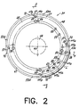
- the cutter 35 is placed close to the cylindrical label drum 34 that has a perforated surface containing orifices through which vacuum and pressure are drawn and expelled to retain a label thereto and later blow the leading edge into engagement with a container. Vacuum and pressure can be drawn and expelled by using various port or solenoid valve systems. However, after many cycles, typically solenoids become inoperable.
- a more efficient apparatus uses manifolds on a hub such as the type disclosed in United States Patent No. 5,344,519 to Galchefski, et al., the disclosure which is hereby incorporated by reference in its entirety.
- the web is drawn through the feed roller system 32a and pressed against the cutter 35 having a vacuum drawn within the cutter.
- the cutter rotates and a cutter blade (not shown), protruding from the cylindrical surface of the cutter, presses against the web to cut the web into individual labels "L", having respective leading and trailing edges 27, 28.
- Several labels are retained on the label drum 34 and rotated in the direction of arrow 38 on the label drum 34 to an adhesive applicator 40, which includes a glue roller 42.
- Adhesive can be applied to the surface of the label that is exposed on the label drum by the glue roller 42, and in accordance with the present invention, applied onto the trailing edge of the label.
- the label drum 34 rotates the leading edge of the label to a point where the leading edge of the label is approximately in alignment with a line 43 between the rotational axis of the drum and the star wheel assembly. As illustrated, the line 43 also coincides with the termination of an arcuate feed guide 43b.
- the container is pushed by a cusp 43a of the star wheel 32 until air blow causes the the leading edge of the label to be engaged to the container and the label wraps itself around the container.
- the container continues its counter-clockwise rotation as indicated by the arrow 21.
- the label drum 34 includes a rotatable outer drum member 45, which is rotatably mounted on a hub 46.
- the drum member 45 includes an outer support surface 47 having a rubber, polyurethane or other resilient material mounted on the outer support surface to form a smooth surface 48 on which the labels rest.
- the labels "L" are not damaged by the high speed operation of the machine. Air and vacuum are drawn or expelled though orifices 49a, 49b, which are formed on the surface 48.
- the orifices 49a, 49b are positioned in an area of the surface 48 on which a label is held.
- the rotatable drum member 45 is rotatably mounted to the hub 46, which is secured to a machine frame (not shown).
- the rotatable drum member 45 includes a side flange surface 50 having an inner set of port openings 52 communicating via a manifold 53 with orifices 49a on the surface 48 where the trailing edge 28 of a label is positioned. That portion of the label drum surface where the trailing edge 28 of the label lies is partially raised to form a protrusion 53a which raises the trailing edge of the label slightly to contact the adhesive roller 42.
- An outer set of port openings 54 communicate via a manifold 55 with the orifices 49b on the surface 48 where the leading edge 27 of a label lies.
- Each manifold 55, 56 communicates via respective air channels 56, 57 to the respective trailing edge and leading edge sets of orifices 49a, 49b.
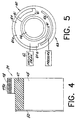
- the hub 46 has secured thereto a fixed vacuum drum flange 60 ( Figure 5), which has a circumferentially extending trailing edge vacuum manifold 61 aligned with the inner port openings 52.
- a source of vacuum 62 is connected to the trailing edge vacuum manifold 61 and draws a vacuum within the manifold, the air channel 57 and through orifices 49a in order to draw a vacuum on the area under the trailing edge of the label to retain a label on the label drum as the drum member 45 rotates about its axis and against the fixed vacuum drum flange 60.
- the trailing edge vacuum manifold 61 extends circumferentially to a point where vacuum is maintained on a trailing edge 28 of the label until the label is completely wrapped around the container.
- the trailing edge vacuum manifold 61 also includes a larger or widened portion 64 to form a first leading edge vacuum manifold 64a that is aligned with outer port openings 54, and leads to the manifold 55, air channel 57, and orifices 49b.
- vacuum source 62 draws a vacuum within both sets of port openings for retaining both the trailing edge 28 and leading edge 27 to the drum surface as the label moves into a label wrapping position 63.
- a leading edge pressure manifold 66 is aligned with the outer port openings 54 and extends after the leading edge vacuum manifold 64a to a point where air pressure is applied by a source of air pressure 68.
- the outer port opening 54 align adjacent the pressure manifold 66, terminating the vacuum draw but blowing the air through orifices 49b.
- the leading edge orifices 49b extend into the label drum surface and are angled relative to that surface 48 so that the air is blown out of the orifices 49b at an angle as described before.
- the trailing edge orifices extend straight into the surface 48 to the manifold 53.
- the orifices may have an hourglass shape, which could enhance a laminar flow from the orifices 49b.
- the laminar flow causes the air to flow under the label and creates the Bernoulli Effect, causing a higher air pressure on top of the label, and thus biasing the label against the surface of the label drum. This is not a desirable effect because the leading edge of the label will not transfer onto the container.
- the air flowing over the slot 70 can create turbulence, thus minimizing the laminar flow of air under the label.
- the angled blow of air from the leading edge orifices 49b maintains the leading edge of the label on the container 13 because the air is directed against the center of the container.
- the leading edge of the label can be maintained on the container by several means, including wet adhesion caused by the capillary action of the water acting as a temporary adhesive, thus retaining the leading edge on the container as the container rotates.
- Wet adhesion is particularly advantageous with thin layer labels.
- air flow from opposite the label drum could be used.
- a timer causes air to flow from the roll-on pad onto the leading edge at a point when the leading edge is adjacent to the roll-on pad.
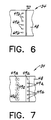
- the air can be forced through two sets of orifices 72, 73.
- the first set 72 is formed to blow air at an angle toward the container and label
- the second set 73 is formed to blow air straight outward from the roll-on pad 16.
- the flow of air from the two sets of orifices 72, 73 minimizes the laminar flow of air under the label and minimizes any biasing of the label against the surface of the roll-on pad. If the roll-on pad has a rough surface, then the two channels as illustrated are preferred. If the roll-on pad has a smooth surface, then only one angled set of orifices 72 could be used, and a slot 77 could formed in the roll-on pad to minimize the laminar flow of air under the label.
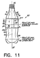
- FIG 11 there is shown one type of container 80 that can be labeled using the existing method and apparatus as described.
- This illustrated container has a contoured surface such as the illustrated convex surface 82.
- any contoured surface will have a label applied which is heat shrunk over the contoured surface.
- Examples of contoured surfaces that can be labeled in accordance with the present invention include but are not limited to circular, elliptical, stepped, sloped, concave and convex surfaces.
- a straight-walled container can also be labeled with the method and apparatus of the present invention. Straight-walled containers typically would not require heat shrinking.
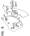
- Figure 8 illustrates a schematic view of a straight wall container where the surface to be labeled is a straight surface that is parallel to the longitudinally extending axis of the container.
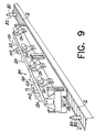
- FIG. 9-11 there is shown a container 80 entering a heat shrink tunnel, indicated generally at 84.
- the container exits the tunnel 84 having the label heat shrunk onto its convex surface 82.
- the illustrated container 80 includes top and bottom body portions 85, 86, and a central vertical axis 87.
- the convex surface 82 is located between the top and bottom body portions 85, 86, and presents a sector of maximum diameter 88.
- the convex surface 82 has a lower convex portion 89 and an upper convex portion 90.
- the upper convex portion 90 has greater convexity than the convexity of the lower convex portion 89 as shown by the dimension "X plus Y" located between the point of maximum convexity on the upper convex portion and the tangent line. This is compared to the smaller dimension "X" corresponding to the spacing between the tangent line and the point of maximum convexity on the lower convex portion.
- the upper convex portion 90 has much greater surface area than the lower convex portion 89.
- the upper body portion 85 includes a generally arcuate tapering section 91 which terminates in an opening 92 on which a cap could be screwed.
- the lower body portion 86 includes an area of maximum diameter 93 so that the portion between the convex surface 82 and the area of maximum diameter 93 on the lower body portion is of lesser diameter as shown in Figure 11. In one embodiment, the maximum diameter is slightly greater than the maximum convex diameter 88.
- Both the upper and lower body portions 85, 86 are fluted as illustrated generally at 94.
- the containers 80 typically are formed from a plastic material such as PET or polyethylene, or other material known to those skilled in the art. The containers could be formed from glass.
- the labels " L " which are applied onto the convex surface typically are rectangular configured and have respective leading, trailing and side edges 27, 28, 28a as shown in Figure 11.
- Labels ' L ' are formed from a thin film layer material and in the embodiment of the container 80 are heat shrinkable for use with the contoured surface. Typically, the labels are about 0,025 to 0,076 mm (0.001 to 0.003 inches) thick.
- the label material could be formed from polyethylene, polypropylene, polyvinylchloride or numerous other types of plastic, heat shrinkable, film material known to those skilled in the art.
- the label can have printed indicia corresponding to identifying, commercial logos and other information.
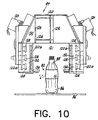
- the container 80 then continues on the conveyor 12 to the heat shrink tunnel illustrated in Figure 9 and schematically in Figure 10.
- the heat shrink tunnel 84 is formed from a first heat tunnel portion 120 and a second heat tunnel portion 122.
- Each heat tunnel portion, 120, 122 is in the present embodiment a forty (40) inch forced air heat tunnel manufactured by CMS Gilbreth Packaging Systems of Trevose, Pennsylvania.
- the tunnel portions 120, 122 are formed of a rugged aluminum construction and each have four energy-efficient blower systems illustrated at 124 .
- One eighty (80) inch oven could also be used instead of two forty (40) inch tunnel portions.
- Each tunnel includes opposing ends, two opposing sides 120a, 122a, and two inner walls 120b, 120b.
- a heating chamber 121 is formed inside each tunne ( Figure 10). The container 80 passes through the chamber 121 on the conveyor without spinning. As illustrated, the tunnel portions 120, 122 are placed over top the conveyor and do not engage the conveyor.
- the tunnel includes an air baffle system 126 and heaters 128 for heating the air drawn in by the blowers 124.
- the air is forced into a manifold area 130 on the upper part of the tunnel 120 and drawn into the side plenums 132, and outward through an air discharge slot 136 extending longitudinally along the inner wall of the lower portion of the tunnel 120. Because the slot extends along the longitudinal length of the tunnel and is simply a long opening and not a leister jet or fan-shaped nozzle, a less harsh blow of hot air is produced.
- the tunnel portions 120, 122 each have an operating temperature of about up to 500° F. and a width adjustment for blowing air from 0 to 21,6 cm (0 inches to 8.5 inches). They have a standard height adjustment of about 30,5 cm (12 inches).
- the tunnels 120, 122 are positioned above the conveyor and can be supported by linear actuator stands 140 to allow a width adjustment of about 0 to 21,6 cm (0 to 8.5 inches) and a height adjustment of about 35,6 cm (14 inches).
- the linear actuator stands can be on a castor assembly include leveling pads.
- the tunnels 120, 122 can be positioned and tilted so that the slots 136 can be positioned substantially horizontally in tunnel two 122 or at a gradual incline such as that shown in tunnel one 120.
- the present invention allows labeling of containers without necessitating an adhesive application on the leading edge of the label. This is advantageous because a label can be stripped from a container without leaving a residue of adhesive on the container, which makes recycling of the container much more efficient and inexpensive. Additionally, because there is no requirement for an adhesive applicator for applying adhesive on the leading edge of a label, during production problems when labels are not fed, an adhesive applicator, would not inadvertently apply adhesive onto the surface of the label drum, requiring as a result production downtime for cleaning the label drum.
Landscapes
- Engineering & Computer Science (AREA)
- Mechanical Engineering (AREA)
- Labeling Devices (AREA)
- Supplying Of Containers To The Packaging Station (AREA)
Claims (30)
- Verfahren zum Etikettieren von Behältern (13, 14) mit den Schritten:Bewegen von Etiketten (L), die auf einer Etikettenwalze (34) gehalten werden, in eine Etikettanlegeposition (63),Befördern eines zu etikettierenden Behälters (13, 14) in die Etikettanlegeposition (63),Blasen von Luft aus der Etikettenwalze (34) auf den vorderen Rand (27) des Etiketts (L) in einem Winkel zur Etikettenwalzenfläche (48) und in einer Richtung vom vorderen Rand (27) rückwärts entlang dem Etikett (L) oder auf dieses, um den vorderen Rand des Etiketts gegen den Behälter (13, 14) zu drücken, undFesthalten des vorderen Randes (27) des Etiketts (L) am Behälter (13, 14), während der Behälter so gedreht wird, daß das Etikett um den Behälter gewickelt wird.
- Verfahren nach Anspruch 1, wobei
der Behälter (13, 14) eine Flüssigkeitsschicht auf der zu etikettierenden Oberfläche hat, um Feuchthaftung des Etiketts (L) auf dem Behälter zu ermöglichen,
und der vordere Rand (27) auf dem Behälter (13, 14) durch Feuchthaftung der Flüssigkeit festgehalten wird. - Verfahren nach Anspruch 1 oder 2, ferner mit den Schritten:Blasen von Luft auf das Etikett (L) und den Behälter (13, 14) von der Seite (72, 73) gegenüber der Etikettenwalze (34), um den vorderen Rand (27) des Etiketts (L) am Behälter (13, 14) festzuhalten, während der Behälter so gedreht wird, daß das Etikett um den Behälter gewickelt wird.
- Verfahren nach Anspruch 1, 2 oder 3, ferner mit den Schritten:Minimieren des laminaren Luftstroms unter dem Etikett (L), um zu verhindern, daß das Etikett gegen die Walzenoberfläche (48) gedrückt wird.
- Verfahren nach einem der Ansprüche 1 bis 4, wobei der vordere Rand des Etiketts durch Feuchthaftung festgehalten wird.
- Verfahren nach einem der Ansprüche 1 bis 5 mit dem Schritt:Blasen von Luft auf das Etikett und den Behälter von der Seite gegenüber der Etikettenwalze, um das Festhalten des vorderen Randes des Etiketts am Behälter zu unterstützen.
- Verfahren nach einem der Ansprüche 1 bis 6 mit dem Schritt:festes Anordnen des hinteren Randes (28) am vorderen Rand (27) durch einen auf den hinteren Rand aufgebrachten Kleber.
- Verfahren nach einem der Ansprüche 1 bis 7 mit dem Schritt:Blasen von Luft über einen Schlitz (70), der in der E-tikettenwalzenoberfläche (48) ausgebildet ist, um den laminaren Luftstrom unter dem Etikett (L) zu minimieren.
- Verfahren nach einem der Ansprüche 1 bis 7 mit dem Schritt:Blasen von Luft von der Seite (72, 73) gegenüber der Etikettenwalze (34) auf eine Weise, um den laminaren Luftstrom unter dem Etikett (L) zu minimieren.
- Verfahren nach einem der Ansprüche 1 bis 9 mit dem Schritt:Andrücken des Behälters (13, 14) an einen feststehenden Gegenhalter (16), der von der Etikettenwalze (34) beabstandet ist, so daß der Behälter zwischen der Etikettenwalze und dem feststehenden Gegenhalter gedreht wird, und Blasen von Luft vom Gegenhalter (16) auf das Etikett (L), während sich der hintere Rand (27) des Etiketts in eine Position nahe dem Gegenhalter bewegt.
- Verfahren nach Anspruch 10 mit dem Schritt:Blasen von Luft vom Gegenhalter (16) in einer Weise, um den laminaren Luftstrom unter dem Etikett (L) zu minimieren.
- Verfahren nach Anspruch 11 mit dem Schritt:Minimieren des laminaren Luftstroms unter dem Etikett (L) durch Blasen von Luft vom Gegenhalter (16) über einen Schlitz (77), der im Gegenhalter (16) ausgebildet ist, oder über eine Kerbe, die in diesen eingeschnitten ist.
- Verfahren nach Anspruch 11 mit dem Schritt:Blasen von Luft vom Gegenhalter (16) in einem Winkel und in einer geraden Richtung zum Gegenhalter, um den laminaren Luftstrom unter dem Etikett (L) zu minimieren.
- Verfahren nach einem der Ansprüche 1 bis 13 mit dem Schritt:Blasen von Luft aus der Etikettenwalze (34) rückwärts gegen das Etikett (L) und den Behälter (13, 14), um das Etikett an der Behälterfläche festzuhalten, während sich der Behälter dreht.
- Verfahren nach einem der Ansprüche 1 bis 14 mit dem Schritt:zeitliches Steuern des Beginns des Blasens des Luftstroms von der Seite gegenüber der Etikettenwalze (34), wenn sich der vordere Rand (27) des Etiketts (L) der Seite gegenüber der Etikettenwalze nähert, und des Beendens des Luftstroms, wenn das Etikett (L) im wesentlichen um den Behälter (13, 14) gewickelt ist.
- Verfahren nach einem der Ansprüche 1 bis 15 mit dem Schritt:Aufschrumpfen des Etiketts (L) auf den Behälter (13, 14), nachdem das Etikett darum gewickelt ist.
- Vorrichtung zum Etikettieren von Behältern mit:einer Etikettenwalze (34), die eine Oberfläche (48) aufweist, auf der Etiketten (L) mit einem vorderen und einem hinteren Rand (27, 28) festgehalten werden, und die zum Bewegen von Etiketten (L) in eine Etikettanlegeposition (63) drehbar ist,einer Behälterzuführung (12, 32) zum Befördern eines Behälters (13, 14) in eine Etikettanlegeposition (63),einer Einrichtung zum Herausblasen von Luft (49b, 68) aus der Etikettenwalze (34) auf den vorderen Rand (27) des Etiketts (L) in einem Winkel zur Etikettenwalzenfläche (48) und in einer Richtung vom vorderen Rand (27) rückwärts entlang dem Etikett (L), um den vorderen Rand des Etiketts gegen den Behälter (13, 14) zu drücken, undeiner Einrichtung zum Festhalten des vorderen Randes (27) des Etiketts (L) am Behälter (13, 14), während der Behälter so gedreht wird, daß das Etikett um den Behälter gewickelt wird.
- Vorrichtung nach Anspruch 17, ferner mit:einer Einrichtung (72, 73, 75) zum Blasen von Luft auf das Etikett (L) und den Behälter (13, 14) von einer Position, die außerhalb der Etikettenwalze (34) angeordnet ist, auf das Etikett (L), um den vorderen Rand (27) des Etiketts am Behälter festzuhalten, während der Behälter so gedreht wird, daß das Etikett um den Behälter gewickelt wird.
- Vorrichtung nach Anspruch 17 oder 18, ferner mit:einer Einrichtung zum Minimieren des laminaren Luftstroms, der unter das Etikett (L) geblasen wird, um zu verhindern, daß das Etikett an die Walzenoberfläche (48) angedrückt wird.
- Vorrichtung nach Anspruch 17, 18 oder 19, wobei die Einrichtung zum Festhalten des vorderen Randes (27) des Etiketts (L) einen Flüssigkeitsfilm auf dem Behälter (13, 14) zur Feuchthaftung des vorderen Randes auf dem Behälter aufweist.
- Vorrichtung nach einem der Ansprüche 17 bis 20, wobei die Einrichtung zum Festhalten des vorderen Randes (27) des Etiketts (L) am Behälter (13, 14) eine Einrichtung(72, 73, 75) zum Blasen von Luft auf das Etikett (L) und den Behälter (13, 14) von einer Position aufweist, die von der Etikettenwalze (34) nach außen beabstandet ist.
- Vorrichtung nach Anspruch 19, wobei die Einrichtung zum Minimieren des laminaren Luftstroms unter dem Etikett (L) einen in der Oberfläche (48) der Etikettenwalze (34) ausgebildeten Kanal (70) aufweist, über den die Luft strömt.
- Vorrichtung nach einem der Ansprüche 17 bis 22, mit einem Kleberauftragegerät (40) zum Aufbringen von Kleber auf den hinteren Rand (28) des Etiketts (L) zum festen Anordnen des hinteren Randes (28) auf dem vorderen Rand (27), wenn sich das Etikett (L) um den Behälter (13, 14) wickelt und der hintere Rand den vorderen Rand überlappt.
- Vorrichtung nach Anspruch 18 mit einem Gegenhalter (16), der von der Etikettenwalze (34) beabstandet ist, zum Eingriff mit einem Behälter (13, 14) und zum Drücken des Behälters gegen die Oberfläche (48) der Etikettenwalze (34), wobei die beabstandete Luftblaseinrichtung Öffnungen (72, 73) am Gegenhalter (16) aufweist, durch die Luft auf das Etikett (L) und den Behälter (13, 14) geblasen wird.
- Vorrichtung nach Anspruch 24, wobei die Öffnungen (72, 73) so konfiguriert sind, daß Luft auf eine Weise zur Minimierung des laminaren Luftstroms unter das Etikett (L) geblasen wird.
- Vorrichtung nach Anspruch 24 mit einem im Gegenhalter (16) ausgebildeten Kanal (77), über den Luft aus Öffnungen (72, 73) im Gegenhalter zur Minimierung des laminaren Luftstroms unter dem Etikett (L) geblasen wird.
- Vorrichtung nach Anspruch 18, wobei die Einrichtung zum Herausblasen von Luft aus der Etikettenwalze (34) Öffnungen (72, 73) aufweist, durch die Luft auf den vorderen Rand (27) des Etiketts (L) geblasen wird, wenn das Etikett in die Etikettanlegeposition (63) bewegt wird.
- Vorrichtung nach einem der Ansprüche 17 bis 27 mit einer Einrichtung (61, 62) zum Abzug eines Vakuums durch Öffnungen (49a), um das Festhalten des Etiketts (L) auf der Etikettenwalze (34) zu unterstützen, bis sich die Etikettenwalze gedreht und das Etikett (L) in die Etikettanlegeposition (63) bewegt hat.
- Vorrichtung nach Anspruch 18 mit einer Einrichtung zur zeitlichen Steuerung des Blasens von Luft von einer Position, die von der Etikettenwalze (34) nach außen beabstandet ist, so daß das Blasen beginnt, wenn sich der vordere Rand (27) des Etiketts (L) in eine Position im wesentlichen gegenüber der Etikettenwalze (34) bewegt hat, und endet, wenn sich das Etikett (L) im wesentlichen um den Behälter (13, 14) gewickelt hat.
- Vorrichtung nach einem der Ansprüche 17 bis 29 mit einem Aufschrumpfofen (84), durch den der Behälter (13, 14) nach Etikettierung zum Aufschrumpfen des Etiketts (L) auf den Behälter (13, 14) läuft.
Applications Claiming Priority (3)
| Application Number | Priority Date | Filing Date | Title |
|---|---|---|---|
| US745820 | 1996-11-12 | ||
| US08/745,820 US5855710A (en) | 1996-11-12 | 1996-11-12 | Method and apparatus for labeling containers |
| PCT/US1997/020242 WO1998021103A1 (en) | 1996-11-12 | 1997-11-10 | Method and apparatus for labeling containers |
Publications (2)
| Publication Number | Publication Date |
|---|---|
| EP0877708A1 EP0877708A1 (de) | 1998-11-18 |
| EP0877708B1 true EP0877708B1 (de) | 2002-04-17 |
Family
ID=24998380
Family Applications (1)
| Application Number | Title | Priority Date | Filing Date |
|---|---|---|---|
| EP97947385A Expired - Lifetime EP0877708B1 (de) | 1996-11-12 | 1997-11-10 | Verfahren und vorrichtung zum etikettieren von behältern |
Country Status (11)
| Country | Link |
|---|---|
| US (1) | US5855710A (de) |
| EP (1) | EP0877708B1 (de) |
| JP (1) | JPH11503702A (de) |
| AT (1) | ATE216336T1 (de) |
| BR (1) | BR9707135A (de) |
| CA (1) | CA2240792A1 (de) |
| DE (1) | DE69712040T2 (de) |
| DK (1) | DK0877708T3 (de) |
| ES (1) | ES2176799T3 (de) |
| PT (1) | PT877708E (de) |
| WO (1) | WO1998021103A1 (de) |
Families Citing this family (14)
| Publication number | Priority date | Publication date | Assignee | Title |
|---|---|---|---|---|
| US5964975A (en) * | 1997-08-18 | 1999-10-12 | Trine Labeling Systems, Inc. | Method and apparatus of labeling cylindrical articles with label having formed curl |
| US6328832B1 (en) | 1998-06-26 | 2001-12-11 | S-Con, Inc. | Labeling apparatus with web registration, web cutting and carrier mechanisms, and methods thereof |
| US6450230B1 (en) | 1999-06-24 | 2002-09-17 | S-Con, Inc. | Labeling apparatus and methods thereof |
| KR20010074485A (ko) * | 1999-02-11 | 2001-08-04 | 린 알. 브레이트 | 아교가 없는 리딩 에지를 가진 라벨을 용기 위에 래핑하기위한 장치 및 방법 |
| US6546958B1 (en) * | 2001-11-30 | 2003-04-15 | B & H Manufacturing Company, Inc. | Multiple cavity valve plate with floating shoe for container labeling apparatus |
| US7343953B2 (en) * | 2004-05-28 | 2008-03-18 | United Parcel Service Of America, Inc. | Method and application for applying labels on surfaces of selected surfaces of varying orientations |
| US20070157566A1 (en) * | 2005-02-09 | 2007-07-12 | Yoav Guthman | Article and method for wrapping such with a polymeric film |
| US20090188613A1 (en) * | 2008-01-28 | 2009-07-30 | Spear Usa, Llc | Method and apparatus for applying pressure sensitive adhesive labels to containers |
| US8828170B2 (en) | 2010-03-04 | 2014-09-09 | Pactiv LLC | Apparatus and method for manufacturing reinforced containers |
| CN105517811A (zh) * | 2013-07-22 | 2016-04-20 | 百事可乐公司 | 用于改进标签在容器上的固定的方法 |
| EP2832652B1 (de) * | 2013-08-02 | 2017-04-26 | Sidel S.p.a. Con Socio Unico | Verfahren zur Handhabung eines bahnförmigen Etikettiermaterials in einem automatisierten Etikettierprozess, Etikettiermaschinenvakuumtrommel und Etikettiermaschine |
| DE202014100148U1 (de) * | 2014-01-14 | 2015-04-16 | Krones Ag | Etikettieraggregat mit Vakuumzylinder |
| US9676573B2 (en) * | 2014-11-17 | 2017-06-13 | Oce-Technologies B.V. | Sheet handling apparatus with rotary drum |
| DE102024122385A1 (de) | 2024-08-06 | 2026-02-12 | Herma Gmbh | Etikettiervorrichtung zum Etikettieren von Mantelflächen von Objekten, insbesondere von zylindrischen Objekten |
Family Cites Families (9)
| Publication number | Priority date | Publication date | Assignee | Title |
|---|---|---|---|---|
| CH598110A5 (de) * | 1975-10-10 | 1978-04-28 | Gretag Ag | |
| US4724036A (en) * | 1986-02-21 | 1988-02-09 | Owens-Illinois Plastic Products Inc. | Progressively ported vacuum drum for labeling machines |
| GB8606629D0 (en) * | 1986-03-18 | 1986-04-23 | Waddington John Plc | Application of labels to articles |
| US4786046A (en) * | 1986-03-15 | 1988-11-22 | John Waddington Plc | Handling of sheet materials |
| US4838982A (en) * | 1987-06-26 | 1989-06-13 | H.G. Weber & Co., Inc. | Patch applicator vacuum cylinder for web material |
| DE4206594A1 (de) * | 1992-03-03 | 1993-09-09 | Alfill Getraenketechnik | Verfahren und vorrichtung zum aufbringen eines rundumetiketts auf einen behaelter |
| US5344519A (en) * | 1992-06-30 | 1994-09-06 | Cms Gilbreth Packaging Systems | Apparatus for applying labels onto small cylindrical articles having improved vacuum and air pressure porting for label transport drum |
| US5275678A (en) * | 1992-07-13 | 1994-01-04 | West Michael J | Method of utilizing surface tension of water to transfer labels onto containers in automatic high-speed labeling machines |
| JPH0699961A (ja) * | 1992-09-17 | 1994-04-12 | Shibuya Kogyo Co Ltd | ラベル取出し装置を備えたラベラ |
-
1996
- 1996-11-12 US US08/745,820 patent/US5855710A/en not_active Expired - Fee Related
-
1997
- 1997-11-10 EP EP97947385A patent/EP0877708B1/de not_active Expired - Lifetime
- 1997-11-10 ES ES97947385T patent/ES2176799T3/es not_active Expired - Lifetime
- 1997-11-10 DK DK97947385T patent/DK0877708T3/da active
- 1997-11-10 WO PCT/US1997/020242 patent/WO1998021103A1/en not_active Ceased
- 1997-11-10 AT AT97947385T patent/ATE216336T1/de not_active IP Right Cessation
- 1997-11-10 JP JP10522669A patent/JPH11503702A/ja active Pending
- 1997-11-10 PT PT97947385T patent/PT877708E/pt unknown
- 1997-11-10 CA CA002240792A patent/CA2240792A1/en not_active Abandoned
- 1997-11-10 DE DE69712040T patent/DE69712040T2/de not_active Expired - Fee Related
- 1997-11-10 BR BR9707135A patent/BR9707135A/pt not_active Application Discontinuation
Also Published As
| Publication number | Publication date |
|---|---|
| PT877708E (pt) | 2002-09-30 |
| WO1998021103A1 (en) | 1998-05-22 |
| DE69712040D1 (de) | 2002-05-23 |
| US5855710A (en) | 1999-01-05 |
| BR9707135A (pt) | 1999-05-18 |
| EP0877708A1 (de) | 1998-11-18 |
| JPH11503702A (ja) | 1999-03-30 |
| CA2240792A1 (en) | 1998-05-22 |
| DE69712040T2 (de) | 2002-10-17 |
| DK0877708T3 (da) | 2002-07-29 |
| ES2176799T3 (es) | 2002-12-01 |
| ATE216336T1 (de) | 2002-05-15 |
Similar Documents
| Publication | Publication Date | Title |
|---|---|---|
| EP0877708B1 (de) | Verfahren und vorrichtung zum etikettieren von behältern | |
| US5964975A (en) | Method and apparatus of labeling cylindrical articles with label having formed curl | |
| US5160570A (en) | Ultra high speed labeling apparatus | |
| US5516576A (en) | Small cylindrical article having film wrap covering | |
| US5403416A (en) | Method of labeling containers with convex surfaces | |
| AU712021B2 (en) | Method of labeling containers | |
| US4923557A (en) | Apparatus and method for applying a heat shrink film to a container | |
| AU637096B2 (en) | Ultra high speed labeling apparatus and method | |
| US4977002A (en) | System for applying heat shrink film to containers and other articles and heat shrinking the same | |
| EP1015325B1 (de) | Verfahren und vorrichtung zur etikettierung von behältern mit durch pressluft unterstütztem transfer der etiketten | |
| GB2187163A (en) | Labelling apparatus | |
| WO1998033711A9 (en) | Method and apparatus for labelling containers with air-blow supported label transfer | |
| US4671843A (en) | Label transport vacuum drum | |
| US6235345B1 (en) | Label adhesive application assembly | |
| US6045616A (en) | Adhesive station and labeling machine | |
| WO1995001912A1 (en) | Labeling containers having deep grooves | |
| MXPA99007098A (en) | Method and apparatus for labelling containers with air-blow supported label transfer | |
| MXPA98005617A (es) | Metodo y aparato para etiquetar contenedores | |
| WO1997009236A1 (en) | Method and apparatus for labeling an article having a convex surface and produced thereby | |
| CA1177792A (en) | Labelling machine | |
| JPH06171631A (ja) | ラベルまたはフィルムセグメントを容器に移動するための装置およびその方法 | |
| MXPA00001696A (en) | Method and apparatus of labeling cylindrical articles with label having formed curl | |
| JP4062635B6 (ja) | 凸表面を有する物品にラベルを貼る方法及び装置 | |
| MXPA97008719A (en) | Method for labeling enva |
Legal Events
| Date | Code | Title | Description |
|---|---|---|---|
| PUAI | Public reference made under article 153(3) epc to a published international application that has entered the european phase |
Free format text: ORIGINAL CODE: 0009012 |
|
| 17P | Request for examination filed |
Effective date: 19980807 |
|
| AK | Designated contracting states |
Kind code of ref document: A1 Designated state(s): AT BE CH DE DK ES FI FR GB GR IE IT LI LU MC NL PT SE |
|
| 17Q | First examination report despatched |
Effective date: 20000804 |
|
| GRAG | Despatch of communication of intention to grant |
Free format text: ORIGINAL CODE: EPIDOS AGRA |
|
| GRAG | Despatch of communication of intention to grant |
Free format text: ORIGINAL CODE: EPIDOS AGRA |
|
| GRAH | Despatch of communication of intention to grant a patent |
Free format text: ORIGINAL CODE: EPIDOS IGRA |
|
| GRAH | Despatch of communication of intention to grant a patent |
Free format text: ORIGINAL CODE: EPIDOS IGRA |
|
| REG | Reference to a national code |
Ref country code: GB Ref legal event code: IF02 |
|
| GRAA | (expected) grant |
Free format text: ORIGINAL CODE: 0009210 |
|
| AK | Designated contracting states |
Kind code of ref document: B1 Designated state(s): AT BE CH DE DK ES FI FR GB GR IE IT LI LU MC NL PT SE |
|
| REF | Corresponds to: |
Ref document number: 216336 Country of ref document: AT Date of ref document: 20020515 Kind code of ref document: T |
|
| REG | Reference to a national code |
Ref country code: CH Ref legal event code: EP |
|
| REG | Reference to a national code |
Ref country code: IE Ref legal event code: FG4D |
|
| REF | Corresponds to: |
Ref document number: 69712040 Country of ref document: DE Date of ref document: 20020523 |
|
| REG | Reference to a national code |
Ref country code: DK Ref legal event code: T3 |
|
| REG | Reference to a national code |
Ref country code: CH Ref legal event code: NV Representative=s name: E. BLUM & CO. PATENTANWAELTE |
|
| ET | Fr: translation filed | ||
| REG | Reference to a national code |
Ref country code: PT Ref legal event code: SC4A Free format text: AVAILABILITY OF NATIONAL TRANSLATION Effective date: 20020607 |
|
| REG | Reference to a national code |
Ref country code: GR Ref legal event code: EP Ref document number: 20020402484 Country of ref document: GR |
|
| PGFP | Annual fee paid to national office [announced via postgrant information from national office to epo] |
Ref country code: FR Payment date: 20021017 Year of fee payment: 6 |
|
| PGFP | Annual fee paid to national office [announced via postgrant information from national office to epo] |
Ref country code: GB Payment date: 20021106 Year of fee payment: 6 |
|
| PG25 | Lapsed in a contracting state [announced via postgrant information from national office to epo] |
Ref country code: LU Free format text: LAPSE BECAUSE OF NON-PAYMENT OF DUE FEES Effective date: 20021110 Ref country code: FI Free format text: LAPSE BECAUSE OF NON-PAYMENT OF DUE FEES Effective date: 20021110 Ref country code: AT Free format text: LAPSE BECAUSE OF NON-PAYMENT OF DUE FEES Effective date: 20021110 |
|
| PG25 | Lapsed in a contracting state [announced via postgrant information from national office to epo] |
Ref country code: SE Free format text: LAPSE BECAUSE OF NON-PAYMENT OF DUE FEES Effective date: 20021111 Ref country code: IE Free format text: LAPSE BECAUSE OF NON-PAYMENT OF DUE FEES Effective date: 20021111 |
|
| PG25 | Lapsed in a contracting state [announced via postgrant information from national office to epo] |
Ref country code: LI Free format text: LAPSE BECAUSE OF NON-PAYMENT OF DUE FEES Effective date: 20021130 Ref country code: CH Free format text: LAPSE BECAUSE OF NON-PAYMENT OF DUE FEES Effective date: 20021130 Ref country code: BE Free format text: LAPSE BECAUSE OF NON-PAYMENT OF DUE FEES Effective date: 20021130 |
|
| REG | Reference to a national code |
Ref country code: ES Ref legal event code: FG2A Ref document number: 2176799 Country of ref document: ES Kind code of ref document: T3 |
|
| PGFP | Annual fee paid to national office [announced via postgrant information from national office to epo] |
Ref country code: DE Payment date: 20021202 Year of fee payment: 6 |
|
| PGFP | Annual fee paid to national office [announced via postgrant information from national office to epo] |
Ref country code: ES Payment date: 20021204 Year of fee payment: 6 |
|
| PG25 | Lapsed in a contracting state [announced via postgrant information from national office to epo] |
Ref country code: DK Free format text: LAPSE BECAUSE OF NON-PAYMENT OF DUE FEES Effective date: 20021231 |
|
| PLBE | No opposition filed within time limit |
Free format text: ORIGINAL CODE: 0009261 |
|
| STAA | Information on the status of an ep patent application or granted ep patent |
Free format text: STATUS: NO OPPOSITION FILED WITHIN TIME LIMIT |
|
| 26N | No opposition filed |
Effective date: 20030120 |
|
| BERE | Be: lapsed |
Owner name: *TRINE LABELING SYSTEMS INC. Effective date: 20021130 |
|
| PG25 | Lapsed in a contracting state [announced via postgrant information from national office to epo] |
Ref country code: NL Free format text: LAPSE BECAUSE OF NON-PAYMENT OF DUE FEES Effective date: 20030601 Ref country code: MC Free format text: LAPSE BECAUSE OF NON-PAYMENT OF DUE FEES Effective date: 20030601 |
|
| EUG | Se: european patent has lapsed | ||
| REG | Reference to a national code |
Ref country code: DK Ref legal event code: EBP |
|
| REG | Reference to a national code |
Ref country code: CH Ref legal event code: PL |
|
| NLV4 | Nl: lapsed or anulled due to non-payment of the annual fee |
Effective date: 20030601 |
|
| REG | Reference to a national code |
Ref country code: IE Ref legal event code: MM4A |
|
| PG25 | Lapsed in a contracting state [announced via postgrant information from national office to epo] |
Ref country code: GB Free format text: LAPSE BECAUSE OF NON-PAYMENT OF DUE FEES Effective date: 20031110 |
|
| PG25 | Lapsed in a contracting state [announced via postgrant information from national office to epo] |
Ref country code: ES Free format text: LAPSE BECAUSE OF NON-PAYMENT OF DUE FEES Effective date: 20031111 |
|
| PG25 | Lapsed in a contracting state [announced via postgrant information from national office to epo] |
Ref country code: PT Free format text: LAPSE BECAUSE OF NON-PAYMENT OF DUE FEES Effective date: 20040531 |
|
| PG25 | Lapsed in a contracting state [announced via postgrant information from national office to epo] |
Ref country code: DE Free format text: LAPSE BECAUSE OF NON-PAYMENT OF DUE FEES Effective date: 20040602 |
|
| PG25 | Lapsed in a contracting state [announced via postgrant information from national office to epo] |
Ref country code: GR Free format text: LAPSE BECAUSE OF NON-PAYMENT OF DUE FEES Effective date: 20040603 |
|
| GBPC | Gb: european patent ceased through non-payment of renewal fee |
Effective date: 20031110 |
|
| PG25 | Lapsed in a contracting state [announced via postgrant information from national office to epo] |
Ref country code: FR Free format text: LAPSE BECAUSE OF NON-PAYMENT OF DUE FEES Effective date: 20040730 |
|
| REG | Reference to a national code |
Ref country code: PT Ref legal event code: MM4A Free format text: LAPSE DUE TO NON-PAYMENT OF FEES Effective date: 20040531 |
|
| REG | Reference to a national code |
Ref country code: FR Ref legal event code: ST |
|
| REG | Reference to a national code |
Ref country code: ES Ref legal event code: FD2A Effective date: 20031111 |
|
| PG25 | Lapsed in a contracting state [announced via postgrant information from national office to epo] |
Ref country code: IT Free format text: LAPSE BECAUSE OF NON-PAYMENT OF DUE FEES Effective date: 20051110 |
|
| PG25 | Lapsed in a contracting state [announced via postgrant information from national office to epo] |
Ref country code: GR Free format text: LAPSE BECAUSE OF NON-PAYMENT OF DUE FEES Effective date: 20020417 |
|
| PG25 | Lapsed in a contracting state [announced via postgrant information from national office to epo] |
Ref country code: PT Free format text: LAPSE BECAUSE OF NON-PAYMENT OF DUE FEES Effective date: 20021110 |