EP0877882B1 - Flow rate control element for ducts - Google Patents
Flow rate control element for ducts Download PDFInfo
- Publication number
- EP0877882B1 EP0877882B1 EP97901645A EP97901645A EP0877882B1 EP 0877882 B1 EP0877882 B1 EP 0877882B1 EP 97901645 A EP97901645 A EP 97901645A EP 97901645 A EP97901645 A EP 97901645A EP 0877882 B1 EP0877882 B1 EP 0877882B1
- Authority
- EP
- European Patent Office
- Prior art keywords
- leaf
- indent
- outdent
- housing
- leaves
- Prior art date
- Legal status (The legal status is an assumption and is not a legal conclusion. Google has not performed a legal analysis and makes no representation as to the accuracy of the status listed.)
- Expired - Lifetime
Links
Images

Classifications
-
- F—MECHANICAL ENGINEERING; LIGHTING; HEATING; WEAPONS; BLASTING
- F16—ENGINEERING ELEMENTS AND UNITS; GENERAL MEASURES FOR PRODUCING AND MAINTAINING EFFECTIVE FUNCTIONING OF MACHINES OR INSTALLATIONS; THERMAL INSULATION IN GENERAL
- F16K—VALVES; TAPS; COCKS; ACTUATING-FLOATS; DEVICES FOR VENTING OR AERATING
- F16K3/00—Gate valves or sliding valves, i.e. cut-off apparatus with closing members having a sliding movement along the seat for opening and closing
- F16K3/02—Gate valves or sliding valves, i.e. cut-off apparatus with closing members having a sliding movement along the seat for opening and closing with flat sealing faces; Packings therefor
- F16K3/03—Gate valves or sliding valves, i.e. cut-off apparatus with closing members having a sliding movement along the seat for opening and closing with flat sealing faces; Packings therefor with a closure member in the form of an iris-diaphragm
Definitions
- the present invention relates to a flow rate control element for ducts, said control element operating based on the iris-diaphragm principle and including an annular housing comprised of a base part with a cover part made to fit thereon, and said housing having therein adapted essentially curved leaves, which are pivotally connected at their one ends to said housing, and further including a control ring having radial slots made thereto in which slots the other ends of the leaves are adapted to move, whereby said leaves are made steplessly rotatable between their closed and open positions by turning the control ring.
- the flow to be restricted by the control element may be a fluid flow such as air, for instance.
- a fluid flow such as air
- different kinds of adjustment means are used for measurement and control of air flow rate.
- the simplest control device is a control damper placed inside the duct so that rotation of the damper plate can control and thus adjust the air flow rate through the duct.
- one drawback of such a control is that the direction of air flow at the control varies according to the position of the control element.
- a generic flow-rate control device of the iris-diaphragm-type having an annular housing comprised of two superimposed halves formed into a base part and a cover part. Between these is adapted a rotatable control ring.
- the control blades or leaves are pivotally connected at their one ends to pivot pins attached to the base part of the control device housing.
- the other ends of the leaves are provided with pins adapted to slide in radial slots made to the control ring surface.
- the invention is characterized in that, for each leaf to be installed, in one part of the housing, advantageously the base part, is formed a nonpenetrating indent or outdent, respectively, whereby to that side of the leaf to be installed facing said indented or outdented side is formed an essentially complementarily shaped outdent or indent, whereby the pivotal cooperation of the outdent/indent pair permits unobstructed rotation of the leaf about its pivot point.
- This arrangement offers significant benefits over the prior art by dispensing with the need for making holes into the housing for fixing the leaves. Furthermore, at least in smaller control devices it is possible to simply insert the leaves in place, whereby the assembly work is speeded and simplified thus offering significant cost savings.
- a preferred embodiment of the invention in characterized in that to both ends of the iris leaf are formed mutually compatible outdents or indents, respectively, so that one end of the leaf has an outdent while the other end has a complementary indent which outdents/indents are mirrored on the other side of the leaf.
- This arrangement has the benefit that the "symmetry" of the leaf faces permits face-independent installation of the leaves.
- Another preferred embodiment of the invention is characterized in that, in both the leaf and the housing, the outdent is shaped essentially hemispherical, while the indent is correspondingly the complementary shape thereof.
- the leaf functions reliably without having any leak problems.
- a still another preferred embodiment of the invention is characterized in that the indents made to the housing are formed flat at their bottoms and that the top surface of the outdent made to the leaves, which is to face the flat bottom of the indent, is correspondingly flat, too.
- This shaping of the outdents/indents is advantageously used in larger flow rate control devices in which the leaves are secured in place by some means. Then, after the leaf is mounted in place, the pivotal joint is compressed with the help of a special tool to form a pivotal joint known as the "toc-lok" joint in the art.
- a further benefit of this embodiment over the prior art is that the control device housing need not be punched for mounting holes of the iris-diaphragm leaves.
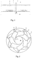
- the flow rate control device shown therein mounted on a duct 1 is an iris-diaphragm flow control device installed inside an annular housing 2.
- the housing is comprised of two superimposed halves, namely, a base part 3 and a cover part 4.
- a control nut 12 for the adjustment of the iris-diaphragm opening, whereby the flow through the device can be set by turning the nut.
- Fig. 2 therein the base part 3 is shown in a scale much enlarged from that of Fig. 1 and now viewed from the right side with respect to Fig. 1.
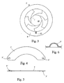
- a control ring 8 (Fig. 9)
- the control ring 8 is an annular ring having its inner diameter made equal to that of the ductwork channel.
- the leaves When the control ring 8 is rotated in a conventional manner circumferentially with respect to the housing 2, the leaves are moved toward the open or closed position depending on the direction of control ring rotation. Accordingly, the variable-diameter iris opening 10 formed by the curved leaves can be thus made larger or smaller.
- the leaves 7 In their one end position, the leaves 7 are entirely moved under the control ring 8, whereby the iris opening 10 is essentially as large as the inner diameter of the duct.
- the leaves 7 close the iris opening 10 entirely or at least essentially.
- Figs. 4-6 the shape of a leaf fulfilling the specifications of an embodiment of the invention.
- To both ends of the leaf are formed, e.g., by pressing an indent/outdent so that the projection formed to one end is mirrored at the other end of the leaf.
- the shape of the indent/outdent 5' is a hemisphere.
- control ring 8 is lowered in a conventional manner over the leaves 7 so that those outdents of the leaves that are not inserted in the indents of the base part 3 will now be inserted in the slots of the control ring 8 in the manner described above.
- the inner perimeter of the control ring 8 is provided with toothing 11 (openings) with a shape to accommodate the meshing of a gearwheel mounted on the cover part 4 when the cover part placed onto the base part.
- the cover part gearwheel is in turn connected via a shaft passing through the wall of the housing with an adjustment nut 12 located on the outer surface of the cover part, whereby the rotation of the nut gears the rotation of the control ring 8 to achieve the adjustment of the flow rate through the device.
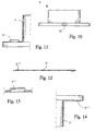
- the wall of the cover part 4 has a pass-through hole 13 (Fig. 11) made thereto.
- the outer perimeter of the control ring carries a graduation (not shown in the diagrams), and outer perimeters of the base part 3 and the cover part 4 are correspondingly provided with windowed openings 14, 15 through which the graduation is visible to the user thus facilitating correct adjustment of the flow rate.
- the window material may be, e.g., transparent plastic.
- Figs. 12-14 show an alternative embodiment of the invention having the indents 5"" of the housing (on the bottom part 3') made flat at their bottoms, and respectively, whereby also the surface of the complementary outdents 5"' of the leaf 7', which is intended to fit against the flat bottom of the indent 5'''', will be flat.
- each abutting pair of outdent and indent is pressed by means of a special tool to deform the outdent/indent pair into a loose, pivotal joint called the toc-lok joint, which locks the leaf inseparably to the base part simultaneously permitting the leaf to rotate in its plane.
- This embodiment is particularly suited for control devices of larger size.
Landscapes
- General Engineering & Computer Science (AREA)
- Engineering & Computer Science (AREA)
- Mechanical Engineering (AREA)
- Flow Control (AREA)
- Paper (AREA)
- Steering Control In Accordance With Driving Conditions (AREA)
- Air-Flow Control Members (AREA)
- Pipe Accessories (AREA)
- Regulation And Control Of Combustion (AREA)
- Fuel-Injection Apparatus (AREA)
- Luminescent Compositions (AREA)
- Golf Clubs (AREA)
- External Artificial Organs (AREA)
- Branch Pipes, Bends, And The Like (AREA)
- Sliding Valves (AREA)
- Fluid-Driven Valves (AREA)
- Massaging Devices (AREA)
- Sanitary Device For Flush Toilet (AREA)
Applications Claiming Priority (3)
| Application Number | Priority Date | Filing Date | Title |
|---|---|---|---|
| FI960480A FI100279B2 (fi) | 1996-02-02 | 1996-02-02 | Virtausputken määränsäät¦elin |
| FI960480 | 1996-02-02 | ||
| PCT/FI1997/000042 WO1997028390A1 (en) | 1996-02-02 | 1997-01-28 | Flow rate control element for ducts |
Publications (2)
| Publication Number | Publication Date |
|---|---|
| EP0877882A1 EP0877882A1 (en) | 1998-11-18 |
| EP0877882B1 true EP0877882B1 (en) | 2002-05-22 |
Family
ID=8545238
Family Applications (1)
| Application Number | Title | Priority Date | Filing Date |
|---|---|---|---|
| EP97901645A Expired - Lifetime EP0877882B1 (en) | 1996-02-02 | 1997-01-28 | Flow rate control element for ducts |
Country Status (12)
| Country | Link |
|---|---|
| EP (1) | EP0877882B1 (da) |
| AT (1) | ATE217946T1 (da) |
| AU (1) | AU1547997A (da) |
| CZ (1) | CZ227798A3 (da) |
| DE (1) | DE69712730D1 (da) |
| DK (1) | DK0877882T3 (da) |
| EE (1) | EE9800207A (da) |
| FI (1) | FI100279B2 (da) |
| NO (1) | NO314813B1 (da) |
| PL (1) | PL328017A1 (da) |
| SE (1) | SE508350C2 (da) |
| WO (1) | WO1997028390A1 (da) |
Families Citing this family (17)
| Publication number | Priority date | Publication date | Assignee | Title |
|---|---|---|---|---|
| US7255012B2 (en) | 2004-12-01 | 2007-08-14 | Rosemount Inc. | Process fluid flow device with variable orifice |
| JP4802314B2 (ja) * | 2006-01-24 | 2011-10-26 | シャープ株式会社 | 窒化物半導体発光素子とその製造方法 |
| US8132783B2 (en) | 2007-09-12 | 2012-03-13 | Lumec Control Products, Inc | Dynamic orifice valve apparatus and method |
| RU2373447C1 (ru) * | 2008-07-21 | 2009-11-20 | Сергей Николаевич Зорин | Регулирующий лепестковый клапан зорина (варианты) |
| US20130299523A1 (en) * | 2012-05-10 | 2013-11-14 | Halliburton Energy Services, Inc. | Proportional controlled orifice for metering granular material |
| US9175786B2 (en) | 2013-08-30 | 2015-11-03 | Lumec Control Products, Inc. | Valve apparatus |
| DK3339814T3 (da) | 2016-12-21 | 2020-08-03 | Fimcim Spa | Anordning installerbar i et luftkonditionerings- og/eller opvarmningssystem, luftkonditionerings- og/eller opvarmningssystem omfattende anordningen og fremgangsmåde til at styre anordningen |
| IT201600129661A1 (it) | 2016-12-21 | 2018-06-21 | Fimcim Spa | Misuratore di pressione differenziale |
| US10502126B2 (en) * | 2017-03-10 | 2019-12-10 | Garrett Transportation I Inc. | Adjustable-trim centrifugal compressor for a turbocharger |
| CN107388646A (zh) * | 2017-08-10 | 2017-11-24 | 珠海格力电器股份有限公司 | 制冷剂流量调节机构和制冷装置 |
| DE102017216311A1 (de) | 2017-09-14 | 2019-03-14 | Continental Automotive Gmbh | Radialverdichter für eine Aufladevorrichtung einer Brennkraftmaschine, sowie Aufladevorrichtung und Lamelle für einen Irisblendenmechanismus sowie Verfahren zur Herstellung einer solchen Lamelle |
| ES2786775A1 (es) * | 2019-04-11 | 2020-10-13 | Cmo Valves Tech S L | Válvula para regulación u obturación del paso de fluidos en conducciones |
| RU2714031C1 (ru) * | 2019-05-07 | 2020-02-11 | Федеральное государственное автономное образовательное учреждение высшего образования "Сибирский федеральный университет" (ФГАОУ ВО СФУ) | Штуцерное устройство для управления потоком рабочего агента |
| CN113261548B (zh) * | 2021-04-28 | 2023-03-28 | 山东泰盛市政园林工程有限公司 | 一种基于市政环保工程用的调节式绿化药物喷洒装置 |
| CN216337921U (zh) * | 2021-10-11 | 2022-04-19 | 华能新能源股份有限公司 | 一种蒸发舟挡板组件 |
| CN117108765B (zh) * | 2023-08-23 | 2024-04-09 | 宁波鑫华银机械有限公司 | 一种风阀执行器 |
| CN120428423B (zh) * | 2025-07-08 | 2025-10-31 | 长春智冉光电科技有限公司 | 一种适用于光刻物镜的可变光阑及方法 |
Family Cites Families (2)
| Publication number | Priority date | Publication date | Assignee | Title |
|---|---|---|---|---|
| US4094492A (en) * | 1977-01-18 | 1978-06-13 | The United States Of America As Represented By The United States Department Of Energy | Variable orifice using an iris shutter |
| NL9401508A (nl) * | 1994-09-16 | 1996-05-01 | Ct Ind Zaandam | Standaangever voor het aanduiden van de stand van een klep. |
-
1996
- 1996-02-02 FI FI960480A patent/FI100279B2/fi not_active IP Right Cessation
-
1997
- 1997-01-28 AT AT97901645T patent/ATE217946T1/de not_active IP Right Cessation
- 1997-01-28 DK DK97901645T patent/DK0877882T3/da active
- 1997-01-28 EE EE9800207A patent/EE9800207A/xx unknown
- 1997-01-28 DE DE69712730T patent/DE69712730D1/de not_active Expired - Lifetime
- 1997-01-28 PL PL97328017A patent/PL328017A1/xx unknown
- 1997-01-28 EP EP97901645A patent/EP0877882B1/en not_active Expired - Lifetime
- 1997-01-28 WO PCT/FI1997/000042 patent/WO1997028390A1/en not_active Ceased
- 1997-01-28 AU AU15479/97A patent/AU1547997A/en not_active Abandoned
- 1997-01-28 CZ CZ982277A patent/CZ227798A3/cs unknown
- 1997-01-30 SE SE9700275A patent/SE508350C2/sv not_active IP Right Cessation
-
1998
- 1998-07-22 NO NO19983370A patent/NO314813B1/no unknown
Also Published As
| Publication number | Publication date |
|---|---|
| SE508350C2 (sv) | 1998-09-28 |
| FI100279B2 (fi) | 2002-02-06 |
| DK0877882T3 (da) | 2002-06-17 |
| EE9800207A (et) | 1998-12-15 |
| NO983370D0 (no) | 1998-07-22 |
| AU1547997A (en) | 1997-08-22 |
| SE9700275L (sv) | 1997-08-03 |
| FI960480A7 (fi) | 1997-08-03 |
| SE9700275D0 (sv) | 1997-01-30 |
| PL328017A1 (en) | 1999-01-04 |
| NO314813B1 (no) | 2003-05-26 |
| NO983370L (no) | 1998-09-29 |
| FI960480A0 (fi) | 1996-02-02 |
| DE69712730D1 (de) | 2002-06-27 |
| ATE217946T1 (de) | 2002-06-15 |
| FI100279B (fi) | 1997-10-31 |
| WO1997028390A1 (en) | 1997-08-07 |
| CZ227798A3 (cs) | 1999-01-13 |
| EP0877882A1 (en) | 1998-11-18 |
Similar Documents
| Publication | Publication Date | Title |
|---|---|---|
| EP0877882A1 (en) | Flow rate control element for ducts | |
| US4006673A (en) | Adjustable air outlet nozzle for automobile heating and venting systems | |
| AU9590198A (en) | Air filtering device | |
| US3159179A (en) | Plugs with diaphragm flow control device | |
| USD413665S (en) | Heating, ventilating, and air conditioning register | |
| US4815934A (en) | Air deflector arrangement | |
| EP2018986A2 (en) | Air diffuser for automobiles | |
| CN101627240B (zh) | 阀 | |
| US2727456A (en) | Adjustable air diffusers | |
| GB2311836A (en) | Wire operated valve | |
| US6234209B1 (en) | Outflow spouts of faucet sets | |
| KR970065040A (ko) | 기류 제어 장치 | |
| JP6936705B2 (ja) | 接続装置及び連結機構 | |
| ES255440U (es) | Dispositivo de corredera para ventilacion | |
| KR200155721Y1 (ko) | 에어콘 배관용 캡 | |
| FR2750200B1 (fr) | Dispositif d'obturation d'un conduit de ventilation, notamment clapet coupe-feu ou volet de desenfumage | |
| ES2303660T3 (es) | Valvula mezcladora para griferias sanitarias. | |
| EP1426694A2 (en) | Device for a valve | |
| KR900002455Y1 (ko) | 공기조화기의 공기공급관 개폐장치 | |
| US2081307A (en) | Damper bearing unit | |
| JPH0448440Y2 (da) | ||
| KR970003471Y1 (ko) | 에어컨 설치용 관통공 마개 | |
| EP0229472A1 (en) | Control knob | |
| KR970026090A (ko) | 자동차 실내 통기구 구조 | |
| SK500042020U1 (sk) | Nastaviteľná vzduchotechnická výustka |
Legal Events
| Date | Code | Title | Description |
|---|---|---|---|
| PUAI | Public reference made under article 153(3) epc to a published international application that has entered the european phase |
Free format text: ORIGINAL CODE: 0009012 |
|
| 17P | Request for examination filed |
Effective date: 19980803 |
|
| AK | Designated contracting states |
Kind code of ref document: A1 Designated state(s): AT BE CH DE DK FR GB LI NL |
|
| AX | Request for extension of the european patent |
Free format text: LT PAYMENT 980803;LV PAYMENT 980803 |
|
| GRAG | Despatch of communication of intention to grant |
Free format text: ORIGINAL CODE: EPIDOS AGRA |
|
| 17Q | First examination report despatched |
Effective date: 20010925 |
|
| GRAG | Despatch of communication of intention to grant |
Free format text: ORIGINAL CODE: EPIDOS AGRA |
|
| GRAH | Despatch of communication of intention to grant a patent |
Free format text: ORIGINAL CODE: EPIDOS IGRA |
|
| GRAH | Despatch of communication of intention to grant a patent |
Free format text: ORIGINAL CODE: EPIDOS IGRA |
|
| GRAA | (expected) grant |
Free format text: ORIGINAL CODE: 0009210 |
|
| AX | Request for extension of the european patent |
Free format text: LT PAYMENT 19980803;LV PAYMENT 19980803 |
|
| PG25 | Lapsed in a contracting state [announced via postgrant information from national office to epo] |
Ref country code: NL Free format text: LAPSE BECAUSE OF FAILURE TO SUBMIT A TRANSLATION OF THE DESCRIPTION OR TO PAY THE FEE WITHIN THE PRESCRIBED TIME-LIMIT Effective date: 20020522 Ref country code: LI Free format text: LAPSE BECAUSE OF FAILURE TO SUBMIT A TRANSLATION OF THE DESCRIPTION OR TO PAY THE FEE WITHIN THE PRESCRIBED TIME-LIMIT Effective date: 20020522 Ref country code: FR Free format text: LAPSE BECAUSE OF FAILURE TO SUBMIT A TRANSLATION OF THE DESCRIPTION OR TO PAY THE FEE WITHIN THE PRESCRIBED TIME-LIMIT Effective date: 20020522 Ref country code: CH Free format text: LAPSE BECAUSE OF FAILURE TO SUBMIT A TRANSLATION OF THE DESCRIPTION OR TO PAY THE FEE WITHIN THE PRESCRIBED TIME-LIMIT Effective date: 20020522 Ref country code: BE Free format text: LAPSE BECAUSE OF FAILURE TO SUBMIT A TRANSLATION OF THE DESCRIPTION OR TO PAY THE FEE WITHIN THE PRESCRIBED TIME-LIMIT Effective date: 20020522 Ref country code: AT Free format text: LAPSE BECAUSE OF FAILURE TO SUBMIT A TRANSLATION OF THE DESCRIPTION OR TO PAY THE FEE WITHIN THE PRESCRIBED TIME-LIMIT Effective date: 20020522 |
|
| REF | Corresponds to: |
Ref document number: 217946 Country of ref document: AT Date of ref document: 20020615 Kind code of ref document: T |
|
| REG | Reference to a national code |
Ref country code: GB Ref legal event code: FG4D |
|
| REG | Reference to a national code |
Ref country code: CH Ref legal event code: EP |
|
| REG | Reference to a national code |
Ref country code: DK Ref legal event code: T3 |
|
| REF | Corresponds to: |
Ref document number: 69712730 Country of ref document: DE Date of ref document: 20020627 |
|
| PG25 | Lapsed in a contracting state [announced via postgrant information from national office to epo] |
Ref country code: DE Free format text: LAPSE BECAUSE OF FAILURE TO SUBMIT A TRANSLATION OF THE DESCRIPTION OR TO PAY THE FEE WITHIN THE PRESCRIBED TIME-LIMIT Effective date: 20020823 |
|
| NLV1 | Nl: lapsed or annulled due to failure to fulfill the requirements of art. 29p and 29m of the patents act | ||
| REG | Reference to a national code |
Ref country code: CH Ref legal event code: PL |
|
| LTIE | Lt: invalidation of european patent or patent extension |
Effective date: 20020522 |
|
| EN | Fr: translation not filed | ||
| PG25 | Lapsed in a contracting state [announced via postgrant information from national office to epo] |
Ref country code: GB Free format text: LAPSE BECAUSE OF NON-PAYMENT OF DUE FEES Effective date: 20030128 |
|
| PLBE | No opposition filed within time limit |
Free format text: ORIGINAL CODE: 0009261 |
|
| STAA | Information on the status of an ep patent application or granted ep patent |
Free format text: STATUS: NO OPPOSITION FILED WITHIN TIME LIMIT |
|
| 26N | No opposition filed |
Effective date: 20030225 |
|
| GBPC | Gb: european patent ceased through non-payment of renewal fee | ||
| PGFP | Annual fee paid to national office [announced via postgrant information from national office to epo] |
Ref country code: DK Payment date: 20050126 Year of fee payment: 9 |
|
| PG25 | Lapsed in a contracting state [announced via postgrant information from national office to epo] |
Ref country code: DK Free format text: LAPSE BECAUSE OF NON-PAYMENT OF DUE FEES Effective date: 20060131 |
|
| REG | Reference to a national code |
Ref country code: DK Ref legal event code: EBP |