EP0877896B1 - Tete de serrage pour le serrage de pieces avec des surfaces d'application unies sur un support, ainsi que verin de serrage de surete a commande pneumatique - Google Patents
Tete de serrage pour le serrage de pieces avec des surfaces d'application unies sur un support, ainsi que verin de serrage de surete a commande pneumatique Download PDFInfo
- Publication number
- EP0877896B1 EP0877896B1 EP97919245A EP97919245A EP0877896B1 EP 0877896 B1 EP0877896 B1 EP 0877896B1 EP 97919245 A EP97919245 A EP 97919245A EP 97919245 A EP97919245 A EP 97919245A EP 0877896 B1 EP0877896 B1 EP 0877896B1
- Authority
- EP
- European Patent Office
- Prior art keywords
- clamping
- clamping plate
- clamping head
- annular part
- head
- Prior art date
- Legal status (The legal status is an assumption and is not a legal conclusion. Google has not performed a legal analysis and makes no representation as to the accuracy of the status listed.)
- Expired - Lifetime
Links
- 230000006835 compression Effects 0.000 claims description 10
- 238000007906 compression Methods 0.000 claims description 10
- 230000037431 insertion Effects 0.000 claims 2
- 238000003780 insertion Methods 0.000 claims 2
- 208000011092 Hand injury Diseases 0.000 abstract description 4
- 239000012530 fluid Substances 0.000 abstract description 2
- 238000010276 construction Methods 0.000 description 2
- 238000004519 manufacturing process Methods 0.000 description 2
- 238000007664 blowing Methods 0.000 description 1
- 238000011109 contamination Methods 0.000 description 1
- 230000008030 elimination Effects 0.000 description 1
- 238000003379 elimination reaction Methods 0.000 description 1
- 238000009434 installation Methods 0.000 description 1
Images
Classifications
-
- F—MECHANICAL ENGINEERING; LIGHTING; HEATING; WEAPONS; BLASTING
- F16—ENGINEERING ELEMENTS AND UNITS; GENERAL MEASURES FOR PRODUCING AND MAINTAINING EFFECTIVE FUNCTIONING OF MACHINES OR INSTALLATIONS; THERMAL INSULATION IN GENERAL
- F16P—SAFETY DEVICES IN GENERAL; SAFETY DEVICES FOR PRESSES
- F16P3/00—Safety devices acting in conjunction with the control or operation of a machine; Control arrangements requiring the simultaneous use of two or more parts of the body
- F16P3/12—Safety devices acting in conjunction with the control or operation of a machine; Control arrangements requiring the simultaneous use of two or more parts of the body with means, e.g. feelers, which in case of the presence of a body part of a person in or near the danger zone influence the control or operation of the machine
- F16P3/16—Safety devices acting in conjunction with the control or operation of a machine; Control arrangements requiring the simultaneous use of two or more parts of the body with means, e.g. feelers, which in case of the presence of a body part of a person in or near the danger zone influence the control or operation of the machine with feeling members moved by the machine
Definitions
- the invention relates to a clamping head for clamping parts with flat attack surfaces on a base and one air-operated safety clamping cylinder for this.
- the invention has for its object a clamping head and a clamping cylinder for this of the type mentioned at the beginning create, with simple structure, operational safety and Elimination of an accident risk should be in the foreground.
- the invention has the advantages over the known that that the clamping head or the safety clamping cylinder for No two-hand operation by the person concerned Make operator more necessary because at Operator's hand injuries even when they have their hand between the clamping head and the part to be clamped, are still excluded. Reliable handling, simple construction and largely maintenance-free further advantages of the subject of the invention.
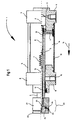
- the invention is based on an exemplary embodiment Drawing explains the new clamping head and the new one Safety clamping cylinders, partly in longitudinal section shown, shows.
- the clamping head 20 is composed of a ring part 21 and a Clamping plate 22 to be placed on the one to be clamped (in the Drawing not shown) formed part.
- the clamping plate 22 is held against the ring part 21 by means of spring force.
- the spring force at one Embodiment of the invention by means of one or more Tension springs (not shown in the drawing) in the clamping head 20 applied.
- the clamping head 20 can be attached to any clamping cylinder be attached.
- the security clamping cylinder 1 initially includes one Cylinder head 8 and a cylinder cover 9, which by means of a Cylinder tube 12 held axially at a distance and by means of a Tie rod 6 are held together axially.
- Cylinder tube 12 runs a piston 4 for actuating a Clamping head 20, the one in question (not in the drawing shown) part should clamp.
- the clamping head 20 serves the Clamping parts with flat contact surfaces on one Document.
- a piston rod 5 is attached to the piston 4 the free end of the clamping head 20 is seated.
- the ring part 21 and the clamping plate form for the compressed air 22 together a pressure chamber 23.
- a compressible O-ring 24 Between the ring part 21 and the clamping plate 22 is a compressible O-ring 24, which seals the pressure chamber 23 to the outside.
- the pressure room 23 also has a longitudinal bore 13 in the piston rod 5 the piston pressure chamber 2 for the piston 4 in terms of pressure constant connection.
- the piston pressure chamber 2 receives compressed air through a narrow, calibrated hole 3 of one (not in the drawing shown) compressed air source for actuating the piston 4th and thus the clamping head 20 in the direction of an arrow 14, that is for clamping a part with flat contact surfaces by means of of the clamping head 20.
- the pressure builds up slowly up to a pressure in the piston pressure chamber 2 of 0.2 to 0.5 bar.
- the narrow, calibrated hole 3 is on the effective area of the Adjusted piston 4.
- the ring part 21 and on the other hand the clamping plate 22 interlock in such a way that after only slight compression of the compressible O-ring 24 a shoulder 25 on the clamping plate 22 directly on one Stop shoulder 26 of the ring part 21 strikes over a large area.
- the power is transmitted from the piston 4 via the Piston rod 5, the ring member 21 and the clamping plate 22 of the Clamping head 20 directly on the one (in the drawing not shown) support lying on, too exciting (in the drawing, not shown) part.
- the clamping plate 22 of the clamping head 20 arrives at not a flat obstacle, for example the hand of one Operator, the clamping plate 22 against the Tilt the ring part 21 so that the support of the shoulder 25 of the Tensioning plate 22 on the stop shoulder 26 of the ring part 21 only done in points.
- the longitudinal bore 13 in the piston rod 5 also the pressure in the piston pressure chamber 2 is reduced, whereby the Piston 4 can currently no longer develop any force and stops together with the clamping head 20.
- the piston rod of the clamping cylinder can be done a separate pneumatic line to the clamping head 20 connected.
Landscapes
- Engineering & Computer Science (AREA)
- General Engineering & Computer Science (AREA)
- Mechanical Engineering (AREA)
- Jigs For Machine Tools (AREA)
- Manipulator (AREA)
- Buffer Packaging (AREA)
- Casting Devices For Molds (AREA)
Claims (7)
- Tête de serrage pour serrer des pièces ayant des surfaces d'engagement planes sur une embase,
caractérisée en ce que la tête de serrage (20) est formée d'une partie annulaire (21) et d'un disque de serrage (22) pour la mise en place sur la pièce à serrer, qui est maintenue en pouvant basculer contre la pièce annulaire (21) au moyen d'une force élastique par interposition d'un joint torique compressible (24), et en ce que la pièce annulaire (21) et le disque de serrage (22) forment, en commun, un espace de pression (23) pour l'air comprimé, qui est en liaison constante, d'un point de vue fluidique, avec un espace de pression de piston, alimenté en air comprimé par l'intermédiaire d'un perçage calibré, d'un vérin de serrage appartenant à la tête de serrage (20), le disque de serrage (22), lors du basculement, étant soulevé du joint torique (24) et l'espace de pression (23) étant ouvert vers l'extérieur, ce qui permet une brusque chute de pression dans l'espace de pression (23). - Tête de serrage selon la revendication 1,
caractérisée en ce que, d'une part, la partie annulaire (21) et, d'autre part, le disque de serrage (22) sont engagés l'un dans l'autre de façon étagée de sorte que, après seulement une légère compression du joint torique (24), un épaulement (25) sur le disque de serrage (22) vient en butée, sur une grande surface, directement sur un épaulement de butée (26) de la partie annulaire (21). - Tête de serrage selon une des revendications 1 ou 2,
caractérisée en ce qu'un ou plusieurs ressorts de traction pour presser le disque de serrage (22) contre la partie annulaire (21) sont agencés dans la tête de serrage (20). - Vérin de serrage de sécurité actionné par de l'air comprimé pour serrer des pièces ayant des surfaces d'engagement planes sur une embase, ayant une tête de serrage selon la revendication 1, qui est déplacée vers l'avant et vers l'arrière par un piston,
caractérisé en ce que la tête de serrage (20) présente une partie annulaire (21) et un disque de serrage (22) pour la mise en place sur la pièce à serrer, qui est maintenue contre la partie annulaire (21) au moyen d'une force élastique par interposition d'un joint torique compressible (24), et en ce que la partie annulaire (21) et le disque de serrage (22) forment, en commun, un espace de pression (23) pour l'air comprimé, qui est toujours en liaison, d'un point de vue fluidique, avec l'espace de pression du piston (2) alimenté en air comprimé par l'intermédiaire d'un perçage calibré. - Vérin de serrage de sécurité selon la revendication 4,
caractérisé en ce qu'un ressort de traction (7) pour presser le disque de serrage (22) contre la partie annulaire (21) est agencé à l'extérieur de la tête de serrage (20). - Vérin de serrage de sécurité selon une des revendications 4 ou 5,
caractérisé en ce que le ressort de traction (7) articulé par une de ses extrémités, de façon solidaire du boítier, dans le vérin de serrage de sécurité (1) est accroché, par l'intermédiaire d'un tirant s'étendant dans la tige de piston (5) pour l'actionnement de la tête de serrage (20), de façon centrale, au disque de serrage (22) de la tête de serrage (20). - Vérin de serrage de sécurité selon une des revendications 4 à 6,
caractérisé en ce que l'espace de pression (23) formé en commun par la partie annulaire (21) et par le disque de serrage (22), du point de vue de la pression, est toujours en liaison avec l'espace de pression du piston (2) par l'intermédiaire d'un perçage longitudinal (13) dans la tige de piston (5) du vérin de serrage de sécurité (1).
Applications Claiming Priority (3)
| Application Number | Priority Date | Filing Date | Title |
|---|---|---|---|
| DE19604414 | 1996-02-07 | ||
| DE19604414 | 1996-02-07 | ||
| PCT/DE1997/000218 WO1997028926A2 (fr) | 1996-02-07 | 1997-02-06 | Tete de serrage pour le serrage de pieces avec des surfaces d'application unies sur un support, ainsi que verin de serrage de surete a commande pneumatique |
Publications (2)
| Publication Number | Publication Date |
|---|---|
| EP0877896A2 EP0877896A2 (fr) | 1998-11-18 |
| EP0877896B1 true EP0877896B1 (fr) | 2001-11-07 |
Family
ID=7784742
Family Applications (1)
| Application Number | Title | Priority Date | Filing Date |
|---|---|---|---|
| EP97919245A Expired - Lifetime EP0877896B1 (fr) | 1996-02-07 | 1997-02-06 | Tete de serrage pour le serrage de pieces avec des surfaces d'application unies sur un support, ainsi que verin de serrage de surete a commande pneumatique |
Country Status (6)
| Country | Link |
|---|---|
| EP (1) | EP0877896B1 (fr) |
| AT (1) | ATE208477T1 (fr) |
| AU (1) | AU2379197A (fr) |
| DE (2) | DE59705278D1 (fr) |
| ES (1) | ES2167735T3 (fr) |
| WO (1) | WO1997028926A2 (fr) |
Families Citing this family (1)
| Publication number | Priority date | Publication date | Assignee | Title |
|---|---|---|---|---|
| CN112140031B (zh) * | 2020-10-09 | 2024-03-26 | 桂林电子科技大学 | 一种nvh测试用夹具及其夹取方法 |
Family Cites Families (3)
| Publication number | Priority date | Publication date | Assignee | Title |
|---|---|---|---|---|
| FR2085446A7 (fr) * | 1970-04-22 | 1971-12-24 | Leroy Johnny | |
| US4527684A (en) * | 1982-12-20 | 1985-07-09 | Fort Wayne Truck Parts & Equipment, Inc. | Ram supported sensing shield for power presses |
| DE3438185A1 (de) * | 1984-10-18 | 1986-04-24 | Johann Weiss Maschinenbau, 7799 Illmensee | Druckmittelbetaetigter spannzylinder mit sicherheitsabschaltung |
-
1997
- 1997-02-06 WO PCT/DE1997/000218 patent/WO1997028926A2/fr not_active Ceased
- 1997-02-06 DE DE59705278T patent/DE59705278D1/de not_active Expired - Fee Related
- 1997-02-06 EP EP97919245A patent/EP0877896B1/fr not_active Expired - Lifetime
- 1997-02-06 DE DE19780072T patent/DE19780072D2/de not_active Expired - Fee Related
- 1997-02-06 AU AU23791/97A patent/AU2379197A/en not_active Abandoned
- 1997-02-06 ES ES97919245T patent/ES2167735T3/es not_active Expired - Lifetime
- 1997-02-06 AT AT97919245T patent/ATE208477T1/de not_active IP Right Cessation
Also Published As
| Publication number | Publication date |
|---|---|
| EP0877896A2 (fr) | 1998-11-18 |
| DE59705278D1 (de) | 2001-12-13 |
| DE19780072D2 (de) | 1999-03-11 |
| WO1997028926A3 (fr) | 1997-09-25 |
| WO1997028926A2 (fr) | 1997-08-14 |
| ATE208477T1 (de) | 2001-11-15 |
| ES2167735T3 (es) | 2002-05-16 |
| AU2379197A (en) | 1997-08-28 |
Similar Documents
| Publication | Publication Date | Title |
|---|---|---|
| DE3403961C2 (de) | Pneumatisch oder hydraulisch betätigbare Kniehebelspannvorrichtung zum Spannen von Karosserieteilen | |
| DE102016015041B4 (de) | Spreiz- und Ziehdorn zum Zentrieren und Spannen von blechförmigen Bauteilen mit zwei koaxial zueinander geführten Kolben | |
| DE2818337B1 (de) | Druckuebersetzter hydropneumatischer Antrieb | |
| EP1385652B1 (fr) | Dispositif de serrage hydromecanique servant notamment a l'extrusion laterale | |
| AT507809A1 (de) | Biegepresse mit einem mehrteiligen pressenbalken | |
| DE3217169C2 (de) | Falzmesserzylinder | |
| DE2605085C3 (de) | Vorrichtung zur Verhütung der Beschädigung von Werkzeug und Werkstück an einer hydraulisch oder pneumatisch betätigten Stanzpresse | |
| EP0090885A1 (fr) | Dispositif de manoeuvre à pression de fluide | |
| EP0106182A1 (fr) | Presse pour le sertissage de manchons, de cosses de câbles et d'objets semblables | |
| EP0877896B1 (fr) | Tete de serrage pour le serrage de pieces avec des surfaces d'application unies sur un support, ainsi que verin de serrage de surete a commande pneumatique | |
| DE3613852C1 (de) | Druckmittelbetaetigbare Kniehebelspannvorrichtung | |
| DE6917177U (de) | Werkzeug-sicherungsvorrichtung fuer pressen | |
| DE3032430A1 (de) | Vorrichtung zur erhoehung des druckes eines an einer druckmittelleitung anstehenden fluids fuer einen verbraucher | |
| DE2451894A1 (de) | Presse mit zwei druckplatten und schnellentlastungseinrichtung | |
| DE3635359A1 (de) | Spannelement | |
| DE19603214C2 (de) | Anordnung zum Schalten eines Druckmediums eines Arbeitszylinders an einer Druckmaschine | |
| DE1079930B (de) | Hydraulische Druckausgleichvorrichtung fuer Arbeitsmaschinen | |
| DE29822443U1 (de) | Absturzsicherung für Hubtische, Hebebühnen u.dgl. | |
| DE943699C (de) | Ladegabel fuer Foerderfahrzeuge, insbesondere fuer Stapel von Formstuecken, z.B. Mauersteinen | |
| DE69009192T2 (de) | Pfeileraufbau. | |
| DE3926847C2 (fr) | ||
| DE4038380C1 (en) | Activator mechanism for press element - includes pressurising cylinder to move element from outer work position to safe spacing with drive means | |
| DE3537337A1 (de) | Spannvorrichtung | |
| DE2419397C2 (de) | Steuerungseinrichtung an einer hydraulischen Gesenkschmiede-Presse | |
| DE972591C (de) | Grubenstempel |
Legal Events
| Date | Code | Title | Description |
|---|---|---|---|
| PUAI | Public reference made under article 153(3) epc to a published international application that has entered the european phase |
Free format text: ORIGINAL CODE: 0009012 |
|
| 17P | Request for examination filed |
Effective date: 19980805 |
|
| AK | Designated contracting states |
Kind code of ref document: A2 Designated state(s): AT CH DE ES FR GB IT LI |
|
| 17Q | First examination report despatched |
Effective date: 19990601 |
|
| GRAG | Despatch of communication of intention to grant |
Free format text: ORIGINAL CODE: EPIDOS AGRA |
|
| GRAG | Despatch of communication of intention to grant |
Free format text: ORIGINAL CODE: EPIDOS AGRA |
|
| GRAH | Despatch of communication of intention to grant a patent |
Free format text: ORIGINAL CODE: EPIDOS IGRA |
|
| GRAH | Despatch of communication of intention to grant a patent |
Free format text: ORIGINAL CODE: EPIDOS IGRA |
|
| GRAA | (expected) grant |
Free format text: ORIGINAL CODE: 0009210 |
|
| AK | Designated contracting states |
Kind code of ref document: B1 Designated state(s): AT CH DE ES FR GB IT LI |
|
| PG25 | Lapsed in a contracting state [announced via postgrant information from national office to epo] |
Ref country code: GB Free format text: LAPSE BECAUSE OF FAILURE TO SUBMIT A TRANSLATION OF THE DESCRIPTION OR TO PAY THE FEE WITHIN THE PRESCRIBED TIME-LIMIT Effective date: 20011107 |
|
| REF | Corresponds to: |
Ref document number: 208477 Country of ref document: AT Date of ref document: 20011115 Kind code of ref document: T |
|
| REG | Reference to a national code |
Ref country code: CH Ref legal event code: EP |
|
| REF | Corresponds to: |
Ref document number: 59705278 Country of ref document: DE Date of ref document: 20011213 |
|
| REG | Reference to a national code |
Ref country code: CH Ref legal event code: NV Representative=s name: KELLER & PARTNER PATENTANWAELTE AG |
|
| REG | Reference to a national code |
Ref country code: GB Ref legal event code: IF02 |
|
| PGFP | Annual fee paid to national office [announced via postgrant information from national office to epo] |
Ref country code: CH Payment date: 20020118 Year of fee payment: 6 |
|
| ET | Fr: translation filed | ||
| GBV | Gb: ep patent (uk) treated as always having been void in accordance with gb section 77(7)/1977 [no translation filed] |
Effective date: 20011107 |
|
| REG | Reference to a national code |
Ref country code: ES Ref legal event code: FG2A Ref document number: 2167735 Country of ref document: ES Kind code of ref document: T3 |
|
| PLBE | No opposition filed within time limit |
Free format text: ORIGINAL CODE: 0009261 |
|
| STAA | Information on the status of an ep patent application or granted ep patent |
Free format text: STATUS: NO OPPOSITION FILED WITHIN TIME LIMIT |
|
| 26N | No opposition filed | ||
| PG25 | Lapsed in a contracting state [announced via postgrant information from national office to epo] |
Ref country code: LI Free format text: LAPSE BECAUSE OF NON-PAYMENT OF DUE FEES Effective date: 20030228 Ref country code: CH Free format text: LAPSE BECAUSE OF NON-PAYMENT OF DUE FEES Effective date: 20030228 |
|
| REG | Reference to a national code |
Ref country code: CH Ref legal event code: PL |
|
| PGFP | Annual fee paid to national office [announced via postgrant information from national office to epo] |
Ref country code: ES Payment date: 20040206 Year of fee payment: 8 |
|
| PGFP | Annual fee paid to national office [announced via postgrant information from national office to epo] |
Ref country code: AT Payment date: 20040211 Year of fee payment: 8 |
|
| PGFP | Annual fee paid to national office [announced via postgrant information from national office to epo] |
Ref country code: FR Payment date: 20040223 Year of fee payment: 8 |
|
| PGFP | Annual fee paid to national office [announced via postgrant information from national office to epo] |
Ref country code: DE Payment date: 20040308 Year of fee payment: 8 |
|
| PG25 | Lapsed in a contracting state [announced via postgrant information from national office to epo] |
Ref country code: IT Free format text: LAPSE BECAUSE OF NON-PAYMENT OF DUE FEES Effective date: 20050206 Ref country code: AT Free format text: LAPSE BECAUSE OF NON-PAYMENT OF DUE FEES Effective date: 20050206 |
|
| PG25 | Lapsed in a contracting state [announced via postgrant information from national office to epo] |
Ref country code: ES Free format text: LAPSE BECAUSE OF NON-PAYMENT OF DUE FEES Effective date: 20050207 |
|
| PG25 | Lapsed in a contracting state [announced via postgrant information from national office to epo] |
Ref country code: DE Free format text: LAPSE BECAUSE OF NON-PAYMENT OF DUE FEES Effective date: 20050901 |
|
| PG25 | Lapsed in a contracting state [announced via postgrant information from national office to epo] |
Ref country code: FR Free format text: LAPSE BECAUSE OF NON-PAYMENT OF DUE FEES Effective date: 20051031 |
|
| REG | Reference to a national code |
Ref country code: FR Ref legal event code: ST Effective date: 20051031 |
|
| REG | Reference to a national code |
Ref country code: ES Ref legal event code: FD2A Effective date: 20050207 |