EP0878280A2 - Rabot électrique à main - Google Patents
Rabot électrique à main Download PDFInfo
- Publication number
- EP0878280A2 EP0878280A2 EP98108380A EP98108380A EP0878280A2 EP 0878280 A2 EP0878280 A2 EP 0878280A2 EP 98108380 A EP98108380 A EP 98108380A EP 98108380 A EP98108380 A EP 98108380A EP 0878280 A2 EP0878280 A2 EP 0878280A2
- Authority
- EP
- European Patent Office
- Prior art keywords
- smoothing
- roll
- tool
- plane
- planer
- Prior art date
- Legal status (The legal status is an assumption and is not a legal conclusion. Google has not performed a legal analysis and makes no representation as to the accuracy of the status listed.)
- Granted
Links
Images

Classifications
-
- B—PERFORMING OPERATIONS; TRANSPORTING
- B27—WORKING OR PRESERVING WOOD OR SIMILAR MATERIAL; NAILING OR STAPLING MACHINES IN GENERAL
- B27C—PLANING, DRILLING, MILLING, TURNING OR UNIVERSAL MACHINES FOR WOOD OR SIMILAR MATERIAL
- B27C1/00—Machines for producing flat surfaces, e.g. by rotary cutters; Equipment therefor
- B27C1/10—Hand planes equipped with power-driven cutter blocks
-
- B—PERFORMING OPERATIONS; TRANSPORTING
- B24—GRINDING; POLISHING
- B24B—MACHINES, DEVICES, OR PROCESSES FOR GRINDING OR POLISHING; DRESSING OR CONDITIONING OF ABRADING SURFACES; FEEDING OF GRINDING, POLISHING, OR LAPPING AGENTS
- B24B23/00—Portable grinding machines, e.g. hand-guided; Accessories therefor
- B24B23/02—Portable grinding machines, e.g. hand-guided; Accessories therefor with rotating grinding tools; Accessories therefor
Definitions
- the present invention concerns an electrically operated portable smoothing planer.
- the most important and engaging step is that of obtaining the shape of what will be the surf inner form.
- This surf for weight reasons is obtained from the manufacturing of low density foam polystyrene blocks.
- the commonly used tool is the electric planer.
- the particular ergonomical shape, the handling, the presence of resting planes and the consequent possibility of adjusting the material removal make the traditional portable electric planer, suitable to smooth the surfaces and to join extended curved lines typical of the surf shape.
- the electric planer proposes again already known tools which in the past were created and used mainly for working wood, recalling their essential characteristics and function, even though increasing their effectiveness with the aid of the electric motor.
- the old planer in fact, as a definition, was made for the wood working and it is suitable to smooth by removing the material as chips, and its two essential elements, handgrips excluded, remain the resting plane, the chisel or cutting edge also called iron which is locked by a stub.
- the essential elements of the present portable electric planer remain: the resting planes and the blade-holder roll endowed with knives which by its vortical action carries out a removal of the wood, still in chips.
- the action remains a cutting one carried out by blades or chisels.
- the material which is interesting to work by using the electric planer is the foam polystyrene or other similar foam plastic material, having a low density and a poor consistency.
- planer blades also known as jack plane
- jack plane were not able to carry out the desired cutting action, but instead tended to strip and disjoin irregularly the worked material in small pieces giving a poorly finished and rough product.
- the foam polystyrene is not even suitable for being used with any kind of electric smoothing machine presently on the market, which even if offering a more refined action, did not allow the resting on such a soft material, and thus a right control in the execution, furthermore the fast clogging of the granular structures on the abrasive surface makes its use scarcely convenient.
- Purpose of the invention is solving this problem by obviating the above mentioned drawbacks.
- a portable electro-manual smoothing planer of the type in which it comprises:
- the innovative idea is thus that of replacing the traditional jack plane roll with a roll which produces an abrasive action, instead of a chip removal, always with a high speed rotation of the roll, equal to not less than 10.000 revolutions a minute, and preferably 15.000 revolutions/minute.
- the cut or removed material which otherwise would clog the spaces between the peaks of the abrasive surface is instead continuously detached by centrifugal force and, by front discharge outlet, laterally convoyed outside of the tool.
- said roll consists of a steel cylinder with dimensions similar to those of the original blade-holder roll but with full and regular external surfaces to which the abrasive surface is fixed.
- the tool may comprise technical and aesthetical characteristics which may recall other tools but have peculiarities which give it abilities and application of use which are completely innovative and are absolutely not common to any other manual electrical tool nowadays available on the market.
- this tool should preferably be light and compact for easing the handling (length 30-65 cm. - width and height about 15 cm.).
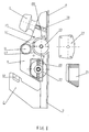
- the machine frame or supporting body will be made up of two shells (6 , 5) in plastic material joined along the middle longitudinal line of the tool by self-threading screws.
- Such shells will determine the same machine aesthetical shape and will have to support, contain and join all the manufacturing details.
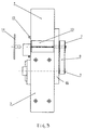
- Both motor (19) and smoothing roll (34, 13) are housed inside of the shells transversally respect to the tool's longitudinal axis, both rest by means of pins on the relative bearings which in turn have their seat on the frame walls. Except for the bearing opposite to the roll transmission side which for practical reasons may be contained by the same roll or, in alternative, by the access flange (14) to the roll, also present on the side opposite to that of transmission.
- the motors used in the tested prototypes had rather low power such as 300 and 500 watt and allowed roll speeds respectively of 17.000 revolutions a minute for the first one, and 14.500 revolutions a minute for the second one. In the first case the abrasive roll had a diameter of 3,5 cm., in the second case of 5 cm. The motors anyway in no case showed any kind of lacks or problems resulting very suitable for the use.
- the two respectively resting and sliding planes are fixed to the shells: the fixed rear one ( 3) and the movable front one (4)
- the second one moves in height at a certain extent.
- the front handgrip, knob-like shaped, (1) may further have the function of carrying out by a joining screw (18) the lifting or lowering of said front resting plane also known as tool front resting plane.
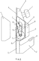
- the external carter on the left side (6) contains and protects the transmission pulleys (7, 9) respectively fixed in the roll and motor pins, protruding from the shell.
- the motor pulley has a diameter of about half the roll's.
- the coupling and transmission will be ensured by a toothed belt (8).
- the carter (21) covers and gives access to the motor main bearing and besides allows to carry out the brushes replacement (20) of the same.
- the smoothing planer comprises the roll (13) interchangeable with a roll having cutting blades or with a roll having an abrasive surface (13, 22).
- a particular roll shape for receiving alternatively either the cutting blade or the abrasive coating, with a normal design solution may be provided.
- a typical and necessary detail of the new tool, found on the right side in correspondence of the smoothing roll seat is the flange or removable carter (14) which allows an easy access to the roll for replacing the abrasive material.
- Said flange will preferably be of metal material requiring a good stiffness, will support the right bearing which in turn will house the roll pin or support a pin in case the bearing was included on the roll itself.
- a series of holes along its perimeter in correspondence of threaded pins fixed on the frame (15) of the smoothing planer which will ease its fixing by means of self-locking bolts or fixing ring nut and the centring respect to the roll axis is provided. Once closed, the flange hermetically matches with the shell for avoiding the dusts coming out from possible slits during the working.
- the machine rear handgrip ( 2) contains the electrical or electronical switch ( 12) and is made up of the same extension of the two shells forming the bearing frame. For handling reasons it would be desirable if this handgrip had an inclination of about 45° respect to the sliding planes.
- the rear wall of the smoothing roll seat obtained inside of the shell (27) follows the shape of this same at a distance between about 3-5 mm, the front part (28) starting at the same distance from the roll in the contact point with the front resting plane it is progressively spaced for creating the exit channel (17) and the necessary hollow for the dust discharge, a typical functional scheme of the centrifugal fans.
- the dust discharging channel (17-11) is commonly placed above the smoothing roll and its exit hole may be located in the most suitable position, in the specific and suitable case, the lateral one.
- the smoothing roll (13) is with no doubt the essential most important and typical member of the smoothing planer, that is the part which combined with the other ones gives the innovative and special performances which distinguish this tool for effectiveness and purpose of usage.
- the roll will meet the material to be worked by rotating in opposite direction respect to the tool advancement direction.
- the roll (13) will have in particular the ability to support the abrasive (22) which will be interplaced on the same, both in case of wear, and if a change of the grain or quality is desired.
- the abrasive will therefore be shaped like sleeves (22) which will be inserted over the smoothing rotating cylinder (13).
- the essential characteristics for the abrasive-holder roll when in working position (22) on the roll (13) are:
- metal materials such as aluminium and steel which may supply the needed requisites and guarantee a better heat absorption and dissipation will be therefore preferable.
- the abrasive spares will be shaped as sleeves (22) with a length equal to the one of the roll which will support them (13) and shall have such a stiffness that will allow them to be inserted on it with a certain pressure without bending or becoming flabby. It is important that between roll and sleeve there is the least possible tolerance being though able to guarantee the insertion and extraction of this latter by a thrust of about 10 kg. This for guaranteeing the maximum integration and functionality between the two elements.
- the tested sleeves prototypes are made up of some fibreglass layers impregnated with epoxidic resin on which later some strong abrasive canvas with a grain of 60 was fixed.
- some tubes having a thickness of about one millimetre (but we could use also higher thicknesses), which once inserted in the abrasive-holder roll will be integral with it guaranteeing regularity and homogeneity of yield.
- two small protrusions ( 25) or guides in diametrically opposed position may be provided and will have the function of avoiding the rotation between roll and sleeve.
- the extractor By using the fissures (26) provided in the roll, the extractor will penetrate up to its base and hook the sleeve on the lower edge by the fins. Gripping the fork with two fingers and laying the hand palm on a small counter-thrust small rod (23) directed against the roll in the pin area, by an easy traction it will be possible to extract the sleeve without an excessive effort.
- This operation together with that of opening and closing the pin holder flange (14) of the roll by acting on the suitable bolts or spring ring nut will be the actions necessary to replace the abrasive, even if this possibility is not as frequent as in other types of smoothing machine.
- the sleeve on which the abrasive (22) is fixed will be instead obtained from tubes of stiff material and high thickness such to guarantee to these same the required external surface stiffness and shape stability (e.g. aluminium tube 5 cm. diameter thickness 2 mm), the self-expanding connecting systems between roll and sleeve will be possibly used with better comfort obtaining the same ensemble functionality.
- the materials to be worked are the most different ones and they may be treated also when coupled and with different or opposite characteristics.
- the new smoothing planer offers optimal solutions for the planes grinding; for the joining of wide radius curved lines; for low density materials working; for fibrous and strong materials working; for removing surfacing or protrusions from flat surfaces also in very soft materials without touching or marking them; it is ideal for plastic laminates where chipping must be avoided; for fibreglass or the like; for wood when small shape corrections are necessary. It has a good working economy and use facility which make it suitable for any user.
- the typical and essential element of this machine is the smoothing roll with its high potentialities and characteristics, but also the other single parts of new smoothing planer must be considered important, because all together they allow to control and graduate the action of the roll itself according to the previously described modalities.
- this tool is able to carry out smoothing or removals with control and precision independently both on soft and friable materials and stiff ones with exceptional fastness and finishing degree in both cases.
- the elements which combined together determine the new tool potential always remain the high smoothing capacity of the abrasive roll (13+22), due to its high working rotational speed besides to its specifical technical characteristics, to the precise control which may be performed on it by using the tool structure itself, and finally to the possibility of manually using the tool on free field in a wide range of situations.
- the stiff external surface will guarantee the proper abrasive life (27), whose deterioration, as found in the tests, does not depend much on the wear but rather on possible movements or on lack of adherence with the roll itself (13), and will further allow the possibility of working different materials, assembled one to the other, without feeling the effects of the different pressures which they would exert in the contact area.
- it will have two small fissures 2 mm large and 5 mm deep placed in diametrically opposed position which will allow both the abrasive (22) sleeve locking both in rotation direction and in the lateral one besides the insertion of the extractor (24). It will alternatively be provided with self-expanding systems for the connection and fixing to the abrasive.
- the smoothing planer will be the possibility of reaching the roll thanks to the removable flange (14) which will allow the abrasive replacements and will be fixed to the frame by three or four threading guides (15) on which some self-locking bolts will be screwed, or a locking ring nut will be placed. Needing stiffness and stability it will preferably be in steel, will be provided with a pin in case the roll is provided with bearing or vice-versa. If the roll had pins and transmissions only on the opposite part the flange may serve only for the structure protection and closing.
- the abrasive sleeve (22) will also be another characteristical element.
- I supplied it will be inserted by pressure around the smoothing roll, may have two small longitudinal internal protrusions in diametrically opposed position which will be inserted in the fissures provided in the roll. Having to be subjected to a certain pressure both for being inserted and extracted it shall have the proper consistency which will avoid also its breaking during the hard stresses.
- the prototypes I tested were obtained from tubes which I made up of fibreglass with a 1/2 mm thickness on which I subsequently glued a strong abrasive canvas of grain 60. Other materials such as cardboard, plastic or aluminium may be used for the abrasive canvas supporting structure if they are safe and strong when used.
- Their internal diameter with a minimum tolerance respect to the roll external diameter shall allow their insertion with about a 10 kg. thrust.
- an extractor will be used which will allow to exert the same force in the opposite direction.
- the extractor (24) indispensable in case the possibility of removing completely the roll from the smoothing planer is not provided, or expansion systems are not provided, it will be necessary for extracting the abrasive sleeve from the roll. It will be made up of a fork as large as the roll's one and its stems will be 2 o 3 cm. longer than the same roll. On the ends it will have two external fins and once inserted along the fissures existing on the roll surfaces it will fasten the sleeve at its base. With two fingers on the fork and the hand palm laid on the counter-thrust small rod (23) directed towards the cylinder the sleeve will be extracted by an easy traction. The possibility that the fork is endowed with a threaded nut and that the also threaded counter-thrust small rod rotating on it determines the force necessary for the sleeve extraction may also be provided.
- the rear handgrip (2) influences the smoothing planer ergonomics and handling; it incorporates the electric or electronic control.
- the front knob (1) it allows an handgrip at 360° and may, once connected with screw and release spring (18), move the front resting plane in height.
- the dust discharging channel (11) it channels the dusts outlet which is naturally caused by the system roll vortical motion which may recall the functional scheme of a centrifugal ventilator.
- the electric motor (19) placed transversal to the longitudinal axis of the smoothing planer transfers the motion to the roll by means of pulleys and toothed belt ( 7 - 8 - 9). It does not need particular power. It may not be present in case the smoothing planer was realised in pneumatical version.
- the frame (5 - 6) normally obtained in suitable plastic material and made up of two shells which besides defining the shape of the same tool supports, includes, and sometimes makes up the elements mentioned and described above. It shall have suitable mechanical and ergonomical characteristics. It may have an infinite series of aesthetical variations but it will always have the function of joining and connecting all the parts and members of the smoothing planer in order to realise the functional ensemble and the interactions which we specified and enhanced many times.
Landscapes
- Life Sciences & Earth Sciences (AREA)
- Engineering & Computer Science (AREA)
- Mechanical Engineering (AREA)
- Wood Science & Technology (AREA)
- Forests & Forestry (AREA)
- Milling, Drilling, And Turning Of Wood (AREA)
- Finger-Pressure Massage (AREA)
- Electrical Discharge Machining, Electrochemical Machining, And Combined Machining (AREA)
- Soil Working Implements (AREA)
- Steroid Compounds (AREA)
- Liquid Crystal (AREA)
- Eye Examination Apparatus (AREA)
- Finish Polishing, Edge Sharpening, And Grinding By Specific Grinding Devices (AREA)
Applications Claiming Priority (2)
| Application Number | Priority Date | Filing Date | Title |
|---|---|---|---|
| IT97TV000063A IT1293358B1 (it) | 1997-05-12 | 1997-05-12 | Pialla levigatrice elettromanuale |
| ITTV970063 | 1997-05-12 |
Publications (3)
| Publication Number | Publication Date |
|---|---|
| EP0878280A2 true EP0878280A2 (fr) | 1998-11-18 |
| EP0878280A3 EP0878280A3 (fr) | 2003-09-24 |
| EP0878280B1 EP0878280B1 (fr) | 2006-11-15 |
Family
ID=11420172
Family Applications (1)
| Application Number | Title | Priority Date | Filing Date |
|---|---|---|---|
| EP98108380A Expired - Lifetime EP0878280B1 (fr) | 1997-05-12 | 1998-05-08 | Rabot électrique à main |
Country Status (5)
| Country | Link |
|---|---|
| EP (1) | EP0878280B1 (fr) |
| AT (1) | ATE345203T1 (fr) |
| DE (1) | DE69836397T2 (fr) |
| ES (1) | ES2276438T3 (fr) |
| IT (1) | IT1293358B1 (fr) |
Cited By (5)
| Publication number | Priority date | Publication date | Assignee | Title |
|---|---|---|---|---|
| EP1512506A1 (fr) * | 2003-09-03 | 2005-03-09 | Ezio Trevisiol | Rabot avec outil abrasif |
| WO2006062439A1 (fr) * | 2004-11-26 | 2006-06-15 | Lev Alexandrovich Ponomarev | Rabot mecanique |
| WO2009060239A3 (fr) * | 2007-11-10 | 2009-08-20 | Exakt Prec Tools Ltd | Améliorations apportées/relatives à des outils électriques |
| GB2460415A (en) * | 2008-05-28 | 2009-12-02 | Black & Decker Inc | Hand held powered planer with handle attached at one end to housing |
| US12589518B2 (en) | 2022-04-25 | 2026-03-31 | Milwaukee Electric Tool Corporation | Hand-held planning tool |
Family Cites Families (8)
| Publication number | Priority date | Publication date | Assignee | Title |
|---|---|---|---|---|
| US1980056A (en) * | 1933-02-08 | 1934-11-06 | Hans U Hedeby | Power actuated hand plane |
| US2540258A (en) * | 1945-08-14 | 1951-02-06 | Thomas J Harris | Hand-operated electric powered dresser |
| US4363343A (en) * | 1980-09-24 | 1982-12-14 | Black & Decker Inc. | Combination guard and rabbeting depth gauge associated with power planer |
| DE3406728A1 (de) * | 1984-02-24 | 1985-08-29 | Karl M. Reich Maschinenfabrik GmbH, 7440 Nürtingen | Handhobelmaschine |
| DE3541728A1 (de) * | 1985-11-26 | 1987-05-27 | Festo Kg | Handhobelmaschine |
| DE8708512U1 (de) * | 1987-06-19 | 1987-08-06 | Festo KG, 7300 Esslingen | Handhobelmaschine |
| CH678032A5 (fr) * | 1989-03-21 | 1991-07-31 | Andre Casal | |
| FR2670421B1 (fr) * | 1990-12-17 | 1995-03-31 | Meffre Olivier | Ponceuse electrique portative. |
-
1997
- 1997-05-12 IT IT97TV000063A patent/IT1293358B1/it active IP Right Grant
-
1998
- 1998-05-08 AT AT98108380T patent/ATE345203T1/de not_active IP Right Cessation
- 1998-05-08 DE DE69836397T patent/DE69836397T2/de not_active Expired - Lifetime
- 1998-05-08 ES ES98108380T patent/ES2276438T3/es not_active Expired - Lifetime
- 1998-05-08 EP EP98108380A patent/EP0878280B1/fr not_active Expired - Lifetime
Cited By (8)
| Publication number | Priority date | Publication date | Assignee | Title |
|---|---|---|---|---|
| EP1512506A1 (fr) * | 2003-09-03 | 2005-03-09 | Ezio Trevisiol | Rabot avec outil abrasif |
| WO2006062439A1 (fr) * | 2004-11-26 | 2006-06-15 | Lev Alexandrovich Ponomarev | Rabot mecanique |
| RU2286246C2 (ru) * | 2004-11-26 | 2006-10-27 | Лев Александрович Пономарев | Механический рубанок |
| WO2009060239A3 (fr) * | 2007-11-10 | 2009-08-20 | Exakt Prec Tools Ltd | Améliorations apportées/relatives à des outils électriques |
| GB2460415A (en) * | 2008-05-28 | 2009-12-02 | Black & Decker Inc | Hand held powered planer with handle attached at one end to housing |
| EP2127830A2 (fr) | 2008-05-28 | 2009-12-02 | Black & Decker, Inc. | Raboteuse |
| US8136559B2 (en) | 2008-05-28 | 2012-03-20 | Black & Decker Inc. | Planer |
| US12589518B2 (en) | 2022-04-25 | 2026-03-31 | Milwaukee Electric Tool Corporation | Hand-held planning tool |
Also Published As
| Publication number | Publication date |
|---|---|
| ES2276438T3 (es) | 2007-06-16 |
| EP0878280B1 (fr) | 2006-11-15 |
| DE69836397D1 (de) | 2006-12-28 |
| DE69836397T2 (de) | 2007-09-27 |
| ITTV970063A1 (it) | 1998-11-12 |
| EP0878280A3 (fr) | 2003-09-24 |
| IT1293358B1 (it) | 1999-02-25 |
| ATE345203T1 (de) | 2006-12-15 |
| ITTV970063A0 (fr) | 1997-05-12 |
Similar Documents
| Publication | Publication Date | Title |
|---|---|---|
| EP0758286B1 (fr) | Accessoire de meuleuse d'angle | |
| US2794303A (en) | Power-driven hand tool | |
| CN201195283Y (zh) | 精加工工具和整套工具 | |
| US4148110A (en) | Rotating scraping or abrading tool | |
| US6632131B1 (en) | Combination rotary cutting and sanding blade | |
| EP0878280A2 (fr) | Rabot électrique à main | |
| KR100882622B1 (ko) | 암석 드릴 비트의 버튼을 위한 연삭도구 | |
| CN209050575U (zh) | 模具内孔精密抛光固定装置 | |
| US1412725A (en) | Grinding machine | |
| US7048617B1 (en) | Method and apparatus for smoothing unfinished surfaces | |
| RU2274518C2 (ru) | Пила ручная электрическая дисковая (варианты) | |
| US6491483B1 (en) | Carving/planing attachment for a rotary hand tool | |
| CN205631041U (zh) | 开槽切磨机 | |
| CN112757059A (zh) | 一种手持全自动精磨砂轮机 | |
| CN215281560U (zh) | 一种轮胎胎侧打磨轮 | |
| CN215700598U (zh) | 一种家具木材加工用平板砂光机 | |
| CN214212462U (zh) | 一种自动磨锯型切割机 | |
| CN220240649U (zh) | 一种多功能磨刀机 | |
| TWM680201U (zh) | 便攜式磨切機鋸片研磨裝置 | |
| CN222200025U (zh) | 一种建筑工程用角磨机 | |
| RU42457U1 (ru) | Пила ручная электрическая дисковая (варианты) | |
| KR200491380Y1 (ko) | 목공용 연마체 | |
| Miller | Sanders | |
| US20040058628A1 (en) | Woodworking method and apparatus | |
| KR900002256Y1 (ko) | 드릴용 연마기 |
Legal Events
| Date | Code | Title | Description |
|---|---|---|---|
| PUAI | Public reference made under article 153(3) epc to a published international application that has entered the european phase |
Free format text: ORIGINAL CODE: 0009012 |
|
| AK | Designated contracting states |
Kind code of ref document: A2 Designated state(s): AT BE CH CY DE DK ES FI FR GB GR IE IT LI LU MC NL PT SE |
|
| AX | Request for extension of the european patent |
Free format text: AL;LT;LV;MK;RO;SI |
|
| PUAL | Search report despatched |
Free format text: ORIGINAL CODE: 0009013 |
|
| AK | Designated contracting states |
Kind code of ref document: A3 Designated state(s): AT BE CH CY DE DK ES FI FR GB GR IE IT LI LU MC NL PT SE |
|
| AX | Request for extension of the european patent |
Extension state: AL LT LV MK RO SI |
|
| RIC1 | Information provided on ipc code assigned before grant |
Ipc: 7B 24D 9/04 B Ipc: 7B 24B 23/02 B Ipc: 7B 27C 1/10 A |
|
| 17P | Request for examination filed |
Effective date: 20040308 |
|
| AKX | Designation fees paid |
Designated state(s): AT CH DE ES FI FR GB LI NL PT SE |
|
| 17Q | First examination report despatched |
Effective date: 20040120 |
|
| GRAP | Despatch of communication of intention to grant a patent |
Free format text: ORIGINAL CODE: EPIDOSNIGR1 |
|
| RAP1 | Party data changed (applicant data changed or rights of an application transferred) |
Owner name: TREVISIOL, EZIO |
|
| RIN1 | Information on inventor provided before grant (corrected) |
Inventor name: TREVISIOL, EZIO |
|
| GRAS | Grant fee paid |
Free format text: ORIGINAL CODE: EPIDOSNIGR3 |
|
| GRAA | (expected) grant |
Free format text: ORIGINAL CODE: 0009210 |
|
| AK | Designated contracting states |
Kind code of ref document: B1 Designated state(s): AT CH DE ES FI FR GB LI NL PT SE |
|
| PG25 | Lapsed in a contracting state [announced via postgrant information from national office to epo] |
Ref country code: NL Free format text: LAPSE BECAUSE OF FAILURE TO SUBMIT A TRANSLATION OF THE DESCRIPTION OR TO PAY THE FEE WITHIN THE PRESCRIBED TIME-LIMIT Effective date: 20061115 Ref country code: FI Free format text: LAPSE BECAUSE OF FAILURE TO SUBMIT A TRANSLATION OF THE DESCRIPTION OR TO PAY THE FEE WITHIN THE PRESCRIBED TIME-LIMIT Effective date: 20061115 Ref country code: AT Free format text: LAPSE BECAUSE OF FAILURE TO SUBMIT A TRANSLATION OF THE DESCRIPTION OR TO PAY THE FEE WITHIN THE PRESCRIBED TIME-LIMIT Effective date: 20061115 |
|
| REG | Reference to a national code |
Ref country code: GB Ref legal event code: FG4D |
|
| REG | Reference to a national code |
Ref country code: CH Ref legal event code: EP |
|
| REF | Corresponds to: |
Ref document number: 69836397 Country of ref document: DE Date of ref document: 20061228 Kind code of ref document: P |
|
| PG25 | Lapsed in a contracting state [announced via postgrant information from national office to epo] |
Ref country code: SE Free format text: LAPSE BECAUSE OF FAILURE TO SUBMIT A TRANSLATION OF THE DESCRIPTION OR TO PAY THE FEE WITHIN THE PRESCRIBED TIME-LIMIT Effective date: 20070215 |
|
| PG25 | Lapsed in a contracting state [announced via postgrant information from national office to epo] |
Ref country code: PT Free format text: LAPSE BECAUSE OF FAILURE TO SUBMIT A TRANSLATION OF THE DESCRIPTION OR TO PAY THE FEE WITHIN THE PRESCRIBED TIME-LIMIT Effective date: 20070416 |
|
| NLV1 | Nl: lapsed or annulled due to failure to fulfill the requirements of art. 29p and 29m of the patents act | ||
| ET | Fr: translation filed | ||
| REG | Reference to a national code |
Ref country code: ES Ref legal event code: FG2A Ref document number: 2276438 Country of ref document: ES Kind code of ref document: T3 |
|
| PLBE | No opposition filed within time limit |
Free format text: ORIGINAL CODE: 0009261 |
|
| STAA | Information on the status of an ep patent application or granted ep patent |
Free format text: STATUS: NO OPPOSITION FILED WITHIN TIME LIMIT |
|
| 26N | No opposition filed |
Effective date: 20070817 |
|
| PGFP | Annual fee paid to national office [announced via postgrant information from national office to epo] |
Ref country code: FR Payment date: 20100525 Year of fee payment: 13 Ref country code: ES Payment date: 20100518 Year of fee payment: 13 |
|
| PGFP | Annual fee paid to national office [announced via postgrant information from national office to epo] |
Ref country code: DE Payment date: 20100518 Year of fee payment: 13 |
|
| PGFP | Annual fee paid to national office [announced via postgrant information from national office to epo] |
Ref country code: CH Payment date: 20100520 Year of fee payment: 13 |
|
| PGFP | Annual fee paid to national office [announced via postgrant information from national office to epo] |
Ref country code: GB Payment date: 20100520 Year of fee payment: 13 |
|
| REG | Reference to a national code |
Ref country code: DE Ref legal event code: R119 Ref document number: 69836397 Country of ref document: DE |
|
| REG | Reference to a national code |
Ref country code: DE Ref legal event code: R119 Ref document number: 69836397 Country of ref document: DE |
|
| REG | Reference to a national code |
Ref country code: CH Ref legal event code: PL |
|
| GBPC | Gb: european patent ceased through non-payment of renewal fee |
Effective date: 20110508 |
|
| PG25 | Lapsed in a contracting state [announced via postgrant information from national office to epo] |
Ref country code: CH Free format text: LAPSE BECAUSE OF NON-PAYMENT OF DUE FEES Effective date: 20110531 Ref country code: LI Free format text: LAPSE BECAUSE OF NON-PAYMENT OF DUE FEES Effective date: 20110531 |
|
| REG | Reference to a national code |
Ref country code: FR Ref legal event code: ST Effective date: 20120131 |
|
| PG25 | Lapsed in a contracting state [announced via postgrant information from national office to epo] |
Ref country code: FR Free format text: LAPSE BECAUSE OF NON-PAYMENT OF DUE FEES Effective date: 20110531 |
|
| PG25 | Lapsed in a contracting state [announced via postgrant information from national office to epo] |
Ref country code: GB Free format text: LAPSE BECAUSE OF NON-PAYMENT OF DUE FEES Effective date: 20110508 |
|
| REG | Reference to a national code |
Ref country code: ES Ref legal event code: FD2A Effective date: 20121116 |
|
| PG25 | Lapsed in a contracting state [announced via postgrant information from national office to epo] |
Ref country code: ES Free format text: LAPSE BECAUSE OF NON-PAYMENT OF DUE FEES Effective date: 20110509 |
|
| PG25 | Lapsed in a contracting state [announced via postgrant information from national office to epo] |
Ref country code: DE Free format text: LAPSE BECAUSE OF NON-PAYMENT OF DUE FEES Effective date: 20111130 |