EP0878326A2 - Blanchet en forme de manchon et machine d'impression l'utilisant - Google Patents
Blanchet en forme de manchon et machine d'impression l'utilisant Download PDFInfo
- Publication number
- EP0878326A2 EP0878326A2 EP98108620A EP98108620A EP0878326A2 EP 0878326 A2 EP0878326 A2 EP 0878326A2 EP 98108620 A EP98108620 A EP 98108620A EP 98108620 A EP98108620 A EP 98108620A EP 0878326 A2 EP0878326 A2 EP 0878326A2
- Authority
- EP
- European Patent Office
- Prior art keywords
- blanket
- tubular
- web
- section
- main
- Prior art date
- Legal status (The legal status is an assumption and is not a legal conclusion. Google has not performed a legal analysis and makes no representation as to the accuracy of the status listed.)
- Granted
Links
Images




Classifications
-
- B—PERFORMING OPERATIONS; TRANSPORTING
- B41—PRINTING; LINING MACHINES; TYPEWRITERS; STAMPS
- B41N—PRINTING PLATES OR FOILS; MATERIALS FOR SURFACES USED IN PRINTING MACHINES FOR PRINTING, INKING, DAMPING, OR THE LIKE; PREPARING SUCH SURFACES FOR USE AND CONSERVING THEM
- B41N10/00—Blankets or like coverings; Coverings for wipers for intaglio printing
- B41N10/02—Blanket structure
-
- B—PERFORMING OPERATIONS; TRANSPORTING
- B41—PRINTING; LINING MACHINES; TYPEWRITERS; STAMPS
- B41N—PRINTING PLATES OR FOILS; MATERIALS FOR SURFACES USED IN PRINTING MACHINES FOR PRINTING, INKING, DAMPING, OR THE LIKE; PREPARING SUCH SURFACES FOR USE AND CONSERVING THEM
- B41N2210/00—Location or type of the layers in multi-layer blankets or like coverings
- B41N2210/02—Top layers
Definitions
- the present invention relates to a tubular blanket to be used for a blanket barrel (cylinder) of a printing machine, and to a printing machine using the tubular blanket.
- a printing unit of an offset printing machine has basically been composed of a blanket and a printing cylinder, and recently, tubular blankets have come into widespread use.
- a printing unit of a blanket-to-blanket printing machine for conducting offset printing onto both surfaces of a web is taken as one example, but the description will be limited to its blanket section.
- Fig. 9 is a perspective view illustratively showing a construction of a principal section of a blanket-to-blanket printing machine using a tubular blanket
- Fig. 10 is a cross-sectional view corresponding to Fig. 9.
- a pair of blanket barrels 1 are disposed in parallel to each other to be in an opposed relation to each other in a state where a web 2 is interposed therebetween. Further, a plurality of compressed air discharging openings (not shown) are made in circumferential surfaces in the vicinity of end portions of the blanket barrels 1, and tubular blankets 3 are respectively fitted over the overall circumferences of the blanket barrels 1 to cover the compressed air discharging openings.
- Each of the tubular blankets 3 serves as an elastic layer constructed by piling up a blanket layer made of a rubber, a fiber, a resin, an adhesive or the like on a sleeve made of an elastic material such as a metal having a high stiffness.
- the tubular blanket 3 always needs to cover the aforesaid compressed air discharging openings in use, and therefore, to say the least of it, the length of the sleeve of the tubular blanket 3 in its axial directions is required to be substantially equal to the length of the circumferential surface of the blanket barrel 1 in its axial direction.
- the blanket barrels 1 are located so that the web 2 is placed between the tubular blankets 3 to be pressed, and further, the blanket barrels 1 are made to be synchronously rotatable in directions of arrows a, b by a non-shown drive unit, respectively.
- non-shown printing cylinders are disposed to be synchronously rotatable while coming into contact with the tubular blankets 3 on both sides, respectively, and inks and water for a picture design to be put into print are applied onto the circumferential surfaces of the printing cylinders.
- the pair of tubular blankets 3 disposed to be in an opposed relation to positions on the upper and lower sides of the web 2, rotates in accordance with the movement of the web 2 while pressing it, the inks transferred onto the tubular blankets 3 are further transferred onto the web 2 to accomplish the offset printing on the web 2.
- the inner diameters of the tubular blankets 3 are enlarged in a manner of discharging compressed air into the gap between the tubular blankets 3 and the blanket barrels 1 from the plurality of non-shown compressed air discharging openings made in the circumferential sections close to the end portions of the blanket barrels 1, thereby facilitating the attaching and detaching operations of the tubular blankets 3.
- the length of the tubular blanket 3 in its axial directions becomes longer than the width of the web 2, and hence, as shown in Fig. 10, if the web width assumes A or B, the tubular blankets 3 positioned above and below the web 2 results in providing contact areas 4 or 4' where the web 2 does not exist on their circumferential surfaces. That is, in the contact areas 4, 4' where the web 2 is absent on the circumferential surfaces of the tubular blankets 3, the tubular blankets 3 positioned on the upper and lower sides of the web 2 are brought directly into contact with each other without intervene of the web 2 notwithstanding that the web 2 is made to be interposed between the tubular blankets 3. Further, the contact areas 4, 4' where the web 2 is absent on the circumferential surfaces of the tubular blankets 3 enlarge as the web 2 has a smaller width.
- the inks or paper particles attached in the web 2 absent areas 4, 4', on the circumferential surfaces of the tubular blankets 3 are left to be accumulated therein, and dry and develop heat due to the pressing force working between the tubular blankets 3 positioned above and below the web 2, which can damage the tubular blankets 3.
- the web 2 may adhere to the ink accumulated in the web 2 absent areas 4, 4' on the circumferential surfaces of the tubular blankets 3, with the result that there is a possibility that the web 2 is wound around the blanket barrels 1 to be cut off.
- the web 2 is wrapped around the blanket barrels 1 in large quantities, and the web 2 is additionally accumulated in the gap between the upper and lower tubular blankets 3 in large quantities, which can make it difficult to put the printing machine into operation because of interfering with the use of the tubular blankets 3.
- the tubular blankets 3 have an excellent high-speed printing performance but are expensive, and are troublesome in replacement, and therefore, in the case of interfering with the use of the tubular blankets 3 as mentioned above, a large loss takes place in economy or in working efficiency.
- the present invention has been developed with a view to eliminating the foregoing problems, and it is therefore an object of this invention to provide a tubular blanket and a printing machine using the tubular blanket which are capable of eliminating the influence from the attachment of inks or paper particles in the web absent area on the circumferential surface of a tubular blanket and of making the web cut-off hard to occur to prevent the interference with the use of the tubular blanket, thereby enhancing the economy and the working efficiency.
- a tubular blanket according to this invention is a tubular blanket for a blanket barrel of a printing machine, and is made up of a main blanket section having at least a portion coming into contact with a print-made web, and a remaining blanket section other than the main blanket section, with the remaining blanket section having a thickness thinner than a thickness of the main blanket section.
- the thickness of the main blanket section is made uniformly.
- the boundary portion between the main blanket section and the remaining blanket section can be constructed as a substantially vertical wall portion.
- the boundary portion between the main blanket section and the remaining blanket section can be constructed to gradually increase in thickness from the remaining blanket section to the main blanket section.
- the width of the main blanket section is made to be slightly larger than that of the web.
- a tubular blanket based printing machine is composed of a first blanket barrel equipped with a first tubular blanket to make a printing on one surface of a web, a second blanket barrel equipped with a second tubular blanket to make a printing on the other surface of the web, with the first and second blanket barrels being disposed in an opposed relation to each other, wherein at least one of the first and second tubular blankets comprises a main blanket section having at least a portion coming into contact with the web, and a remaining blanket section other than the main blanket section which has a thickness thinner than the thickness of the main blanket section.
- each of the first and second tubular blankets includes the main blanket section having at least the portion coming into contact with the web, and the remaining blanket section other than the main blanket section which has a thickness thinner than the thickness of the main blanket section.
- the thickness of the main blanket section is made uniformly.
- the boundary portion between the main blanket section and the remaining blanket section can be constructed as a substantially vertical wall portion.
- the boundary portion between the main blanket section and the remaining blanket section can be constructed to gradually increase in thickness from the remaining blanket section to the main blanket section.
- a tubular blanket based printing machine is provided with a blanket barrel having a tubular blanket thereon to make a printing on one surface of a web, wherein the tubular blanket comprises a main blanket section having at least a portion coming into contact with the web, and a remaining blanket section other than the main blanket section formed such that its thickness is thinner than the thickness of the main blanket section.
- the thickness of the main blanket section is made uniformly.
- the boundary portion between the main blanket section and the remaining blanket section can be constructed as a substantially vertical wall portion, or the boundary portion between the main blanket section and the remaining blanket section can be constructed to gradually increase in thickness from the remaining blanket section to the main blanket section.
- a main blanket section having a portion coming into contact with a print-made web and a remaining blanket section other than the main blanket section.
- the main blanket section is made to have a uniform thickness and the thickness of the remaining blanket section is made to be thinner than that of main blanket section.
- the web absent contact area is reducible to a slight quantity, and since in the remaining blanket section there is a gap between the tubular blankets disposed in an opposed relation to each other, even if inks or paper particles coming from the periphery are attached onto the web absent area, the attached inks or paper particles do not cause the damage to the tubular blankets and the replacement of the expensive tubular blankets is reducible, thus improving the economy and the working efficiency.
- the width of the main blanket section is made to be slightly larger than the width of the web, it is possible to reduce the web absent contact area up to a slight quantity, with the result that inks or paper particles hardly adhere to the web absent contact area, thereby further enhancing the aforesaid effects or advantages.
- a tubular blanket according to the embodiment of this invention is, as well as the prior tubular blanket, for use in a printing unit of a blanket-to-blanket printing machine for conducting a printing on a web.
- the blanket-to-blanket printing machine comprises blanket barrels 1, 1, printing cylinders 12, 12, water-giving rollers 13, 13 and ink applying units 14, 14 which are respectively symmetrically disposed in opposed relation with respect to a web 2.
- the blanket barrels 1, 1 paired are disposed in parallel to each other to press the web 2 therebetween, while tubular blankets (not shown in Fig. 5) are fitted over the circumferential surfaces of the blanket barrels 1, 1, respectively, so that the web 2 is pressed in a state of being held between the tubular blankets.
- the blanket barrels 1, 1 are designed to be synchronously rotatable by a drive unit (not shown) in directions of arrows a, b.
- the printing cylinders 12, 12 are respectively located to be synchronously rotatable in directions of arrows d, e while coming into contact with the tubular blankets fitted over the blanket barrels 1, 1.
- the water-giving rollers 13, 13 are disposed to be synchronously rotatable in directions of arrows f, g while coming into contact therewith, thereby applying water onto the circumferential surfaces of the printing cylinders 12, 12.
- the ink applying units 14, 14 are additionally situated in order to apply inks corresponding to a picture pattern to be printed onto the circumferential surfaces of the printing cylinders 12, 12.
- the ink applying units 14, 14 apply inks corresponding to a picture pattern to be printed onto the circumferential surfaces of the printing cylinders 12, 12, respectively.
- the blanket barrels 1, 1 each having the tubular blanket thereon and the printing cylinders 12, 12 are first synchronously rotationally driven in contacting conditions, so that the inks applied onto the circumferential surfaces of the printing cylinders 12, 12 are transferred onto the circumferential surfaces of the tubular blankets on the blanket barrels 1, 1, respectively.
- the pair of blanket barrels 1, 1 disposed in an opposed relation to each other in a state where the web 2 is interposed therebetween rotate in the directions of the arrows a, b in accordance with the movement of the web 2 while pressing the web 2 therebetween, whereupon the inks transferred onto the tubular blankets are again transferred onto the web 2, thereby accomplishing the offset printing for the web 2.
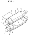
- a pair of blanket barrels 1 are placed in an opposed relation to each other to interpose a web 2 therebetween, and a plurality of compressed air discharging openings 10 are made in portions of circumferential surfaces of the blanket barrels 1 in the vicinity of their end portions to be arranged in circumferential directions, and tubular blankets 8 are fitted over the overall circumferences of the blanket barrels 1 to cover the compressed air discharging openings 10.
- the blanket barrels 1 are positioned so that their tubular blankets 8 press the web 2 therebetween, and the blanket barrels 1 located on the upper and lower sides of the web 2 are made to be synchronously rotatable by a non-shown drive unit in directions of arrows a, b, respectively, as mentioned before.
- a non-shown drive unit in directions of arrows a, b, respectively, as mentioned before.
- each of the tubular blankets 8 is composed of a main blanket section 8a having a portion coming into contact with the web 2 and remaining blanket sections 8b other than the main blanket section 8a. Further, the main blanket section 8a is formed to have a uniform blanket thickness t, while the remaining blanket sections 8 b are formed to have a blanket thickness t' ( ⁇ t) thinner than the thickness of the main blanket section 8a.
- the tubular blanket 8 serves as an elastic layer constructed by piling up a blanket layer 7 made of a rubber, a fiber, a resin, an adhesive or the like on a sleeve 6 made of an elastic material such as a metal having a high stiffness.
- the width of the sleeve 6 of the tubular blanket 8 in its axial directions is set to deal with the width of a printing plate (not shown) corresponding to the maximum sheet width, and in general the width thereof is made to substantially coincide with a width which allows covering the compressed air discharging openings 10 made in the circumferential surface of the blanket barrel 1.
- the main blanket section 8a is set to assume an area slightly larger than the range coming contact with the web 2, that is, set to occupy a range spreading to positions on both sides in the axial directions of the blanket barrel 1 to slightly (for example, 5 to 10 mm) exceed the sheet width, and is formed to assume a uniform thickness t, whereas the remaining blanket sections 8b other than the main blanket section 8a (that is, the sections existing from both the side positions, defining the range slightly exceeding the sheet width, to both the end portions) are formed to have a thickness t' thinner than the blanket thickness t.
- tubular blankets 8 are also replaced with ones corresponding to that width. For instance, if the webs to be used have two different widths, two kinds of tubular blankets 8 are prepared.
- the main blanket section 8a is set at a substantially central position in its axial directions to occupy an area obtained by respectively adding slight ranges 4 to both sides of a range with a width equal to the width of the web A, and the main blanket section 8a is formed to have a uniform thickness t, whereas the remaining blanket sections 8b other than the main blanket section 8a are formed to have a thickness t' smaller than the blanket thickness t.
- gap areas 5 are defined between the remaining blanket sections 8b of the upper and lower tubular blankets 8.
- the main blanket section 8 a' is set at a substantially central position in its axial directions to occupy an area obtained by respectively adding slight ranges 4' to both sides of a range with a width equal to the width of the web B, and the main blanket section 8 a' is formed to have a uniform thickness t, whereas the remaining blanket sections 8 b' other than the main blanket section 8 a' are formed to have a thickness t' smaller than the blanket thickness t.
- gap areas 5' are defined between the remaining blanket sections 8 b' of the upper and lower tubular blankets 8'.
- the remaining blanket sections 8b, 8 b' define web absent gap areas 5, 5,' and the web absent contact areas only result in slightly existing between the upper and lower tubular blankets 8, 8' for pressing the web 2.
- the tubular blankets signify not only the tubular blankets designated at numeral 8 but also the tubular blankets denoted at numeral 8', and the tubular blankets 8 mentioned represent all the tubular blankets.
- the main blanket sections signify not only the main blankets designated at numeral 8a but also the main blankets depicted at numeral 8 a', and the main blanket sections 8a mentioned represent all the main blanket sections.
- the remaining blanket sections also include the remaining blanket sections denoted at numerals 8 b', and the remaining blanket sections 8b mentioned represent all the remaining blanket sections 8b.
- Figs. 4A to 4C are partially cross-sectional views showing structures of the tubular blankets 8 for reducing the thickness of the tubular blankets 8 to create the web 2 absent gap areas 5.
- a lower layer of the blanket layer 7 extends to end portions of the sleeve 6 in its axial directions, while a portion of an upper layer of the blanket layer 7 is cut off, thereby making the blanket thickness t' smaller than the blanket thickness t.
- the sections having a blanket thickness t'' thinner than the blanket thickness t depend upon only the sleeve 6, and the axial end surfaces of the blanket layer 7 piled up on the sleeve 6 are formed to have an inclined (tapered) portion expanding toward the lower layer side (the side placed into contact with the sleeve 6).
- the sections having a blanket thickness t'' thinner than the blanket thickness t rely on only the sleeve 6, and the axial end surfaces of the blanket layer 7 piled up on the sleeve 6 are formed to take a vertical condition.
- the printing cylinders 12 synchronously rotatable with the tubular blankets 8 are located to come into contact with the tubular blankets 8, respectively, as shown in Fig. 5.
- the printing cylinders 12 synchronously rotate while coming into contact with the tubular blankets 8 after inks for a picture pattern and water are applied onto the circumferential surfaces of the printing cylinders 12, the inks are transferred onto the circumferential surfaces of the tubular blankets 8. Further, when the tubular blankets 8 where the inks transferred on their circumferential surfaces rotate while coming into contact with the web 2, the printing on the web is achievable.
- the tubular blankets 8 rotating in accordance with the movement of the web 2 while pressing the web therebetween, in the gap between the main blanket sections 8a of the tubular blankets 8 located on the upper and lower sides of the web 2, the inks transferred onto the circumferential surfaces of the main blanket sections 8a of the tubular blankets 8 are again transferred onto the web 2, thereby accomplishing the offset printing on the web 2.
- the width of the web 2 is substantially equal to the width of the main blanket section 8a, the web 2 absent areas 4, 4' only exist by small amounts on the circumferential surfaces of the main blanket sections 8a, with the result that the inks or paper particles coming from the periphery hardly adhere to the web 2 absent contact areas 4, 4'.
- the inks or paper particles coming from the periphery stick to the web 2 absent gap areas 5, 5' (that is, the remaining blanket sections 8b), because the gaps are defined between the upper and lower remaining blanket sections 8b so that the inks or paper particles coming from the periphery are free from being pressed between the remaining blanket sections 8b, the inks or paper particles do not dry or generate heat, with the result that the damage of the tubular blankets 8 is avoidable.
- the web 2 absent contact areas 4, 4' only exist slightly on the circumferential surfaces of the tubular blankets 8, the web 2 does not adhere to the ink accumulated in the web 2 absent areas 4, 4', thereby preventing the cut-off of the web 2 due to the winding around the blanket barrels 1.
- the web 2 does not stick to the accumulated ink. Accordingly, also from this point of view, it is possible to prevent the web cut-off originating from the winding of the web 2 around the blanket barrels 1. In addition, because of preventing the web cut-off originating from the web winding, it is possible to eliminate the interference with the use of the tubular blankets 8.
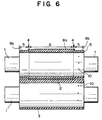
- tubular blanket 8 is employed in connection with both the blanket barrels of the blanket-to-blanket printing machine, this invention is not limited to this structure, and it is also appropriate that, as shown in Fig. 6, the tubular blanket 8 is used for only one blanket barrel 1 of the blanket-to-blanket printing machine.
- the blanket-to-blanket printing machine shown in Fig. 6 is also a printing machine using a tubular blanket, and the tubular blanket 8 is fitted over only one of the pair of blanket barrels 1 disposed in an opposed relation to each other in a state where the web 2 is put therebetween in a way similar in the above-described embodiment shown in Fig. 2, whereas a tubular blanket 3 similar to that of the prior art shown in Fig. 10 is fitted over the other blanket barrel 1.
- the tubular blanket and the printing machine based upon the tubular blanket according to the modification of the first embodiment of this invention can prevent the accumulation, drying and heat generation of the inks or paper particles coming from the periphery, thus preventing the damage of the tubular blanket 8 and the adhesion of the web 2 to the ink accumulated in the web 2 absent areas so that the web cut-off originating from the winding of the web 2 around the blanket barrels 1 is avoidable.
- the web 2 does not adhere to the accumulated ink. Also from this point of view, it is possible to prevent the web cut-off originating from the winding of the web 2 around the blanket barrels 1. In addition, because of preventing the web cut-off originating from the web winding, it is possible to eliminate the interference with the use of the tubular blankets 8.
- tubular blankets 8 are employed for the blanket-to-blanket printing machine
- this invention is not limited to this, and it is also appropriate that they are applied to a printing machine of a type of pressing blankets against a web on an impression cylinder as shown in Figs. 7 and 8.
- the printing machine shown in Figs. 7 and 8 is a printing machine using tubular blankets, and is composed of an impression cylinder 11, a blanket barrel 1, a printing cylinder 12, a water-giving roller 13 and an ink applying unit 14 for accomplishing a single-sided printing on the web 2 on the impression cylinder 11.
- the blanket barrel 1 is placed at a position being in an opposed relation to the impression cylinder 11 with respect to the web 2 to be in parallel to the impression cylinder 11, and the blanket barrel 1 carries, thereon, a tubular blanket 8 having the same structure as that in the aforesaid embodiment shown in Fig. 2.
- the blanket barrel 1 and the impression cylinder 11 are made to be synchronously rotatable in directions of arrows a, b through the use of a non-shown drive unit.
- the printing cylinder 12 is disposed to come into contact with the circumferential surface of the tubular blanket 8, and the printing cylinder 12 is disposed to be rotatable synchronously with the blanket barrel 1 in a direction of an arrow d.
- the water-giving roller 13 is located to come into contact with the circumferential surface of the printing cylinder 12, and when the water-giving roller 13 synchronously rotates in a direction of an arrow f, water is given onto the circumferential surface of the printing cylinder 12.
- the ink applying unit 14 is placed on the circumferential surface of the printing cylinder 12 to apply inks corresponding to a picture pattern to be printed onto the circumferential surface of the printing cylinder 12.
- the printing cylinder 12 and the tubular blanket 8 first rotate synchronously while coming into contact with each other, so that the inks applied onto the circumferential surface of the printing cylinder 12 are transferred onto the circumferential surface of the tubular blanket 8 on the blanket barrel 1.
- the blanket barrel 1 and the impression cylinder 11 disposed in an opposed relation to each other to interpose the web 2 therebetween rotate in the directions of the arrows a, b in accordance with the movement of the web 2 while pressing the web 2 therebetween, the inks transferred onto the tubular blanket 8 are again transferred onto the web 2, thereby accomplishing the offset printing on the web 2.
- tubular blanket according to this invention is applied to a printing machine of a type of pressing a blanket against a web on an impression cylinder, it is possible to obtain the same effects as those attainable when applying it to the above-described blanket-to-blanket printing machine.
- tubular blankets 8 are replaced in the case of largely changing the width of the web 2, this invention is not limited to this, and in the case that the width of the web 2 takes various values, if sacrificing that the web 2 absent blanket contact area becomes slightly larger, it may be possible to reduce the kinds of tubular blankets 8 to be prepared.
- tubular blanket 8 is designed such that the main blanket section 8a is formed at its axial central section and the remaining blanket sections 8b are formed on both the sides of the main blanket section 8a, this invention is not limited to this, and the main blanket section 8a can be at any position on the tubular blanket 8 in its axial directions.
Landscapes
- Printing Plates And Materials Therefor (AREA)
- Rotary Presses (AREA)
Applications Claiming Priority (3)
| Application Number | Priority Date | Filing Date | Title |
|---|---|---|---|
| JP122634/97 | 1997-05-13 | ||
| JP12263497 | 1997-05-13 | ||
| JP12263497A JP3510452B2 (ja) | 1997-05-13 | 1997-05-13 | 印刷機,印刷ユニットおよび筒状ブランケットセット |
Publications (3)
| Publication Number | Publication Date |
|---|---|
| EP0878326A2 true EP0878326A2 (fr) | 1998-11-18 |
| EP0878326A3 EP0878326A3 (fr) | 1999-03-17 |
| EP0878326B1 EP0878326B1 (fr) | 2003-07-30 |
Family
ID=14840834
Family Applications (1)
| Application Number | Title | Priority Date | Filing Date |
|---|---|---|---|
| EP98108620A Expired - Lifetime EP0878326B1 (fr) | 1997-05-13 | 1998-05-12 | Blanchet en forme de manchon et machine d'impression l'utilisant |
Country Status (8)
| Country | Link |
|---|---|
| US (1) | US6148726A (fr) |
| EP (1) | EP0878326B1 (fr) |
| JP (1) | JP3510452B2 (fr) |
| KR (1) | KR100255631B1 (fr) |
| CN (1) | CN1096963C (fr) |
| CA (1) | CA2236061C (fr) |
| DE (1) | DE69816705T2 (fr) |
| TW (1) | TW535729U (fr) |
Cited By (1)
| Publication number | Priority date | Publication date | Assignee | Title |
|---|---|---|---|---|
| WO2006119525A3 (fr) * | 2005-05-10 | 2007-02-15 | Oebs Gmbh | Blanchet |
Families Citing this family (9)
| Publication number | Priority date | Publication date | Assignee | Title |
|---|---|---|---|---|
| DE10257746B3 (de) * | 2002-12-10 | 2004-06-24 | Man Roland Druckmaschinen Ag | Formzylinder einer Rotationsdruckmaschine, insbesondere einer Offsetdruckmaschine |
| DE19921388A1 (de) * | 1999-05-10 | 2000-11-16 | Roland Man Druckmasch | Rotationsdruckmaschine mit einem Form-, einem Übertragungs- und einem Gegendruckzylinder |
| DE10257231A1 (de) * | 2002-12-07 | 2004-06-24 | Rieter Ingolstadt Spinnereimaschinenbau Ag | Reibbelag für Reibwalze zum Antreiben einer Spule an einer Textilmaschine |
| DE102006046521A1 (de) * | 2006-09-29 | 2008-04-03 | Man Roland Druckmaschinen Ag | Druckwerk einer Druckmaschine |
| EP2207684B1 (fr) * | 2007-10-19 | 2011-11-23 | KHS GmbH | Dispositif d'impression de bouteilles ou de récipients similaires sur la surface extérieure des récipients |
| US8307764B2 (en) * | 2009-02-17 | 2012-11-13 | Luminite Products Corporation | Printing sleeve |
| US20120097057A1 (en) * | 2010-10-22 | 2012-04-26 | Manroland Ag | Printing unit and a printing press and printing roller or impression cylinder of a printing press |
| CN104302481B (zh) * | 2012-05-18 | 2016-07-06 | 阪本顺 | 橡皮布组件、转印辊、印刷装置 |
| CN111169191B (zh) * | 2020-01-22 | 2022-03-25 | 上海摩伽智能家居有限公司 | 一种双色桌面的制作方法 |
Family Cites Families (16)
| Publication number | Priority date | Publication date | Assignee | Title |
|---|---|---|---|---|
| US1428795A (en) * | 1921-11-17 | 1922-09-12 | Charles P Mezger | Printing device |
| US1576726A (en) * | 1924-04-24 | 1926-03-16 | Arthur B Davis | Printing roller and method of making same |
| US1804139A (en) * | 1926-01-16 | 1931-05-05 | Frank W Adsit | Printing blanket for offset work |
| US2447991A (en) * | 1946-06-13 | 1948-08-24 | Hoe & Co R | Resilient bearer for offset presses |
| GB1091068A (en) | 1965-11-19 | 1967-11-15 | Grace W R & Co | A method joining superposed fabrics and the products of such method |
| US3750250A (en) * | 1972-08-31 | 1973-08-07 | Bingham S Co | Printer{40 s roller and method of making same |
| DE2514294C2 (de) | 1975-04-02 | 1985-01-03 | Continental Gummi-Werke Ag, 3000 Hannover | Mantel einer Walze für die Druckbehandlung von Warenbahnen |
| DE3139494C2 (de) * | 1981-09-30 | 1983-11-10 | Herlitz Ag, 1000 Berlin | Walze |
| WO1986005447A1 (fr) * | 1985-03-20 | 1986-09-25 | Huber & Suhner Ag, Kabel-, Kautschuk-, Kunststoff- | Rouleau interchangeable et son utilisation dans des machines d'impression |
| DE68926788T2 (de) * | 1989-09-19 | 1997-03-06 | Kinyosha Kk | Verdichtbare kautschukdecke für offsetdruck |
| DE9203874U1 (de) * | 1992-03-23 | 1993-03-04 | Eduard Küsters Maschinenfabrik GmbH & Co KG, 4150 Krefeld | Walze mit Manchon |
| US5215013A (en) * | 1992-07-07 | 1993-06-01 | Heidelberg Harris Inc. | Printing blanket with noise attenuation |
| DE4340915A1 (de) * | 1993-02-23 | 1994-08-25 | Heidelberger Druckmasch Ag | Auswechselbare Andrückhülse |
| US5577443A (en) * | 1995-02-08 | 1996-11-26 | Luminite Products Corporation | Printing sleeve construction |
| US5515781A (en) * | 1995-08-08 | 1996-05-14 | Luminite Products Corporation | Nickel printing sleeve with protective hard rubber rims |
| US6062138A (en) * | 1999-03-30 | 2000-05-16 | Howard A. Fromson | Offset printing having blanket cylinder with blanket having different thicknesses |
-
1997
- 1997-05-13 JP JP12263497A patent/JP3510452B2/ja not_active Expired - Fee Related
-
1998
- 1998-04-27 KR KR1019980014961A patent/KR100255631B1/ko not_active Expired - Fee Related
- 1998-04-27 CA CA002236061A patent/CA2236061C/fr not_active Expired - Fee Related
- 1998-04-29 TW TW091214121U patent/TW535729U/zh not_active IP Right Cessation
- 1998-05-12 EP EP98108620A patent/EP0878326B1/fr not_active Expired - Lifetime
- 1998-05-12 US US09/076,001 patent/US6148726A/en not_active Expired - Fee Related
- 1998-05-12 CN CN98108317A patent/CN1096963C/zh not_active Expired - Fee Related
- 1998-05-12 DE DE69816705T patent/DE69816705T2/de not_active Expired - Fee Related
Cited By (1)
| Publication number | Priority date | Publication date | Assignee | Title |
|---|---|---|---|---|
| WO2006119525A3 (fr) * | 2005-05-10 | 2007-02-15 | Oebs Gmbh | Blanchet |
Also Published As
| Publication number | Publication date |
|---|---|
| EP0878326A3 (fr) | 1999-03-17 |
| EP0878326B1 (fr) | 2003-07-30 |
| DE69816705T2 (de) | 2004-03-11 |
| CA2236061C (fr) | 2002-02-12 |
| CA2236061A1 (fr) | 1998-11-13 |
| DE69816705D1 (de) | 2003-09-04 |
| KR19980086648A (ko) | 1998-12-05 |
| JPH10309880A (ja) | 1998-11-24 |
| JP3510452B2 (ja) | 2004-03-29 |
| TW535729U (en) | 2003-06-01 |
| KR100255631B1 (ko) | 2000-05-01 |
| CN1198989A (zh) | 1998-11-18 |
| CN1096963C (zh) | 2002-12-25 |
| US6148726A (en) | 2000-11-21 |
Similar Documents
| Publication | Publication Date | Title |
|---|---|---|
| JP4263568B2 (ja) | 孔版印刷装置 | |
| EP0884176B1 (fr) | Blanchet et méthode pour son montage sur un cylindre | |
| US6148726A (en) | Tubular blanket and printing machine using tubular blanket | |
| US6484632B2 (en) | Rubber cylinder sleeve, especially for web-fed rotary offset printing machines | |
| US5979322A (en) | Environmentally safe, ink repellent, anti-marking flexible jacket covering having alignment stripes, centering marks and pre-fabricated reinforcement strips for attachment onto transfer cylinders in a printing press | |
| JPH06183172A (ja) | オフセット・ゴムブランケットスリーブ | |
| JP3370167B2 (ja) | 管状印刷スリーブの列形成を低減する装置 | |
| JP3600209B2 (ja) | スクリーン印刷胴を備えた印刷ユニット | |
| JPS6213818Y2 (fr) | ||
| JP3285711B2 (ja) | 孔版印刷用ドラム | |
| JPH05330224A (ja) | 裏写りを生じない孔版印刷法及び孔版印刷装置 | |
| GB2264766A (en) | Sheet-guiding cylinders | |
| US6202558B1 (en) | Apparatus for reducing procession of a tubular printing sleeve | |
| JP5332017B2 (ja) | 新聞印刷用ブランケット胴及びこのブランケット胴を備えた新聞印刷用オフセット輪転印刷機 | |
| US6101943A (en) | Cylinder cleaning device and cleaning method | |
| JP3578182B2 (ja) | インキ漏れ防止構造を有する孔版印刷機 | |
| CN1980793B (zh) | 轮转胶版印刷机 | |
| US20070272104A1 (en) | Coating device | |
| JP2001138477A (ja) | 特にウェブ式オフセット輪転印刷機用のゴム胴スリーブ | |
| JP2746540B2 (ja) | オフセット輪転印刷機の印刷機構 | |
| EP1090773A3 (fr) | Machine d'impression au pochoir | |
| JP3276239B2 (ja) | 孔版印刷ドラム | |
| US6874417B2 (en) | Sleeve-shaped transfer element for rotary printing machines | |
| JPH11179876A (ja) | オフセット輪転印刷機の印刷胴装置 | |
| EP1122081A3 (fr) | Machine d'impression au pochoir. |
Legal Events
| Date | Code | Title | Description |
|---|---|---|---|
| PUAI | Public reference made under article 153(3) epc to a published international application that has entered the european phase |
Free format text: ORIGINAL CODE: 0009012 |
|
| AK | Designated contracting states |
Kind code of ref document: A2 Designated state(s): DE FR GB IT |
|
| AX | Request for extension of the european patent |
Free format text: AL;LT;LV;MK;RO;SI |
|
| PUAL | Search report despatched |
Free format text: ORIGINAL CODE: 0009013 |
|
| AK | Designated contracting states |
Kind code of ref document: A3 Designated state(s): AT BE CH CY DE DK ES FI FR GB GR IE IT LI LU MC NL PT SE |
|
| AX | Request for extension of the european patent |
Free format text: AL;LT;LV;MK;RO;SI |
|
| 17P | Request for examination filed |
Effective date: 19990419 |
|
| AKX | Designation fees paid |
Free format text: DE FR GB IT |
|
| 17Q | First examination report despatched |
Effective date: 19991202 |
|
| GRAH | Despatch of communication of intention to grant a patent |
Free format text: ORIGINAL CODE: EPIDOS IGRA |
|
| GRAH | Despatch of communication of intention to grant a patent |
Free format text: ORIGINAL CODE: EPIDOS IGRA |
|
| GRAA | (expected) grant |
Free format text: ORIGINAL CODE: 0009210 |
|
| AK | Designated contracting states |
Designated state(s): DE FR GB IT |
|
| REG | Reference to a national code |
Ref country code: GB Ref legal event code: FG4D |
|
| REF | Corresponds to: |
Ref document number: 69816705 Country of ref document: DE Date of ref document: 20030904 Kind code of ref document: P |
|
| ET | Fr: translation filed | ||
| PLBE | No opposition filed within time limit |
Free format text: ORIGINAL CODE: 0009261 |
|
| STAA | Information on the status of an ep patent application or granted ep patent |
Free format text: STATUS: NO OPPOSITION FILED WITHIN TIME LIMIT |
|
| REG | Reference to a national code |
Ref country code: GB Ref legal event code: 746 Effective date: 20040615 |
|
| 26N | No opposition filed |
Effective date: 20040504 |
|
| REG | Reference to a national code |
Ref country code: FR Ref legal event code: D6 |
|
| PGFP | Annual fee paid to national office [announced via postgrant information from national office to epo] |
Ref country code: DE Payment date: 20080515 Year of fee payment: 11 |
|
| PGFP | Annual fee paid to national office [announced via postgrant information from national office to epo] |
Ref country code: IT Payment date: 20080526 Year of fee payment: 11 |
|
| PGFP | Annual fee paid to national office [announced via postgrant information from national office to epo] |
Ref country code: GB Payment date: 20080514 Year of fee payment: 11 |
|
| REG | Reference to a national code |
Ref country code: FR Ref legal event code: ST Effective date: 20090119 |
|
| PG25 | Lapsed in a contracting state [announced via postgrant information from national office to epo] |
Ref country code: FR Free format text: LAPSE BECAUSE OF NON-PAYMENT OF DUE FEES Effective date: 20080602 |
|
| REG | Reference to a national code |
Ref country code: FR Ref legal event code: D3 |
|
| GBPC | Gb: european patent ceased through non-payment of renewal fee |
Effective date: 20090512 |
|
| REG | Reference to a national code |
Ref country code: FR Ref legal event code: ST Effective date: 20100129 |
|
| PGFP | Annual fee paid to national office [announced via postgrant information from national office to epo] |
Ref country code: FR Payment date: 20080514 Year of fee payment: 11 |
|
| PG25 | Lapsed in a contracting state [announced via postgrant information from national office to epo] |
Ref country code: GB Free format text: LAPSE BECAUSE OF NON-PAYMENT OF DUE FEES Effective date: 20090512 |
|
| PG25 | Lapsed in a contracting state [announced via postgrant information from national office to epo] |
Ref country code: DE Free format text: LAPSE BECAUSE OF NON-PAYMENT OF DUE FEES Effective date: 20091201 |
|
| PG25 | Lapsed in a contracting state [announced via postgrant information from national office to epo] |
Ref country code: IT Free format text: LAPSE BECAUSE OF NON-PAYMENT OF DUE FEES Effective date: 20090512 |