EP0878352A2 - Dispositif de verrouillage pour un conteneur sur le châssis d'un véhicule - Google Patents
Dispositif de verrouillage pour un conteneur sur le châssis d'un véhicule Download PDFInfo
- Publication number
- EP0878352A2 EP0878352A2 EP98108606A EP98108606A EP0878352A2 EP 0878352 A2 EP0878352 A2 EP 0878352A2 EP 98108606 A EP98108606 A EP 98108606A EP 98108606 A EP98108606 A EP 98108606A EP 0878352 A2 EP0878352 A2 EP 0878352A2
- Authority
- EP
- European Patent Office
- Prior art keywords
- pivot
- housing
- plug pin
- locking
- pin
- Prior art date
- Legal status (The legal status is an assumption and is not a legal conclusion. Google has not performed a legal analysis and makes no representation as to the accuracy of the status listed.)
- Granted
Links
- 244000261422 Lysimachia clethroides Species 0.000 claims abstract description 9
- 230000008878 coupling Effects 0.000 claims description 7
- 238000010168 coupling process Methods 0.000 claims description 7
- 238000005859 coupling reaction Methods 0.000 claims description 7
- 238000007789 sealing Methods 0.000 claims description 4
- 239000000565 sealant Substances 0.000 claims description 3
- 238000012423 maintenance Methods 0.000 claims 1
- 230000007246 mechanism Effects 0.000 abstract description 4
- 238000005553 drilling Methods 0.000 description 5
- 238000009434 installation Methods 0.000 description 4
- 230000015572 biosynthetic process Effects 0.000 description 2
- 238000006073 displacement reaction Methods 0.000 description 2
- 239000000428 dust Substances 0.000 description 2
- 238000005755 formation reaction Methods 0.000 description 2
- 241000309551 Arthraxon hispidus Species 0.000 description 1
- 230000009471 action Effects 0.000 description 1
- 230000008901 benefit Effects 0.000 description 1
- 230000008859 change Effects 0.000 description 1
- 238000011109 contamination Methods 0.000 description 1
- 238000005260 corrosion Methods 0.000 description 1
- 230000007797 corrosion Effects 0.000 description 1
- 238000000151 deposition Methods 0.000 description 1
- 230000000694 effects Effects 0.000 description 1
- 230000003993 interaction Effects 0.000 description 1
- 238000000034 method Methods 0.000 description 1
- 230000008569 process Effects 0.000 description 1
- 230000009467 reduction Effects 0.000 description 1
- 230000003068 static effect Effects 0.000 description 1
- 230000001960 triggered effect Effects 0.000 description 1
Images

Classifications
-
- B—PERFORMING OPERATIONS; TRANSPORTING
- B60—VEHICLES IN GENERAL
- B60P—VEHICLES ADAPTED FOR LOAD TRANSPORTATION OR TO TRANSPORT, TO CARRY, OR TO COMPRISE SPECIAL LOADS OR OBJECTS
- B60P7/00—Securing or covering of load on vehicles
- B60P7/06—Securing of load
- B60P7/13—Securing freight containers or forwarding containers on vehicles
- B60P7/132—Securing freight containers or forwarding containers on vehicles twist-locks for containers or frames
Definitions
- the invention relates to a lock for containers on one Vehicle chassis, especially with a Gooseneck chassis a housing, a plug that is slidably mounted in the housing and a pivot that is rotatably mounted in the housing.
- Vehicle chassis to hold 40-foot and 20-foot containers are becoming more and more than so-called gooseneck chassis educated. These have a lower rear Section and a raised front section.
- For Containers with or without Gooseneck tunnel are on front end of the front section special and for example known from the German utility model G 91 14 903.7 Locks arranged on both sides. These have an in horizontally level sliding pin to secure a Containers with a Gooseneck tunnel and one around a vertical Axis rotatable pivot to secure a container different design.
- the two different locking mechanisms are each in the same housing a lock are held and operated separately. To do this, controls be led out of the housing. The operator Person must know exactly what type of container this is corresponding control element in which position to stand Has.
- the well-known housing is due to the many breakthroughs the housing is susceptible to dirt. Operating errors are due to the various setting options easily possible.
- the object of the present invention is a lock of the type mentioned at the beginning to create the easy to use and is arranged as protected as possible.
- the object of the lock according to the invention is characterized in that that plug and trunnion operationally with each other are coupled, such that when the pivot is actuated also the plug is moved and / or that at Actuation of the plug the pivot is rotated.
- the described coupling of the plug pin and the pivot pin allows a common for both functions To provide an operating element.
- Trunnion and plug pin is only one at all Operating element required. So you can get one out of the case led out end of the pivot a transverse to the axis of rotation arranged lever may be provided.
- the housing then faces a maximum of three breakthroughs, namely for both ends of the Pivot and for one end of the plug. The housing can otherwise be closed. Pollution and This effectively prevents corrosion of the individual parts.
- the pivot pin advantageously has a toothing on, in particular a gear segment over about 80 ° to 140 °.
- the plug or one in the housing is analogous to this arranged extension of the same with a toothing provided, especially in the manner of a rack or Triebstock gearing.
- the two gears mentioned by The pivot pin and plug pin interlock and thus have an effect a forced coupling of the functions.
- end of the pivot led out of the housing Transverse to its axis of rotation arranged lever provided in particular cranked against an underside of the housing is trained. This allows the pivot to be short and still can be between the lever and the bottom the housing is sufficient and for handling the Lever ergonomically reasonable distance be given.
- Another and independent aspect of the invention relates to Design of the housing. This is for optional cultivation largely on the left or right side of the vehicle chassis constructed symmetrically, with top wall, bottom wall, side walls and small end walls, with an opening in the top wall and preferably also in the lower wall for receiving the pivot and openings in the end walls for particular optional Leading out of the plug pin.
- the plug protrudes from one end only Housing out. Nevertheless, preferably both end faces point of the housing openings through corresponding Lids or covers can be closed. With a simple one Change the arrangement of the plug inside the housing can the lock either for a left or right-hand attachment to be prepared.
- An unused opening in the area of the front wall can be in any execution of the lock to accommodate a Position lamp or a component prepared for this be provided. Separate brackets for such lights then omitted.
- Another aspect of the invention sees sealants in the field the openings for spigots and / or pivots before, in particular Sealing rings and / or sliding bushes.
- the sealing of the im remaining closed housing is almost complete. A It is then no longer possible for dust and dirt to penetrate.
- an independent aspect of the invention relates to one Locking with a plug and / or a pivot and with a new drive. So it is provided that on or in Housing at least one pneumatically or hydraulically acting Piston-cylinder unit for actuating the plug pin and / or the pivot is arranged. That way remote control of the locking possible. Especially in speed-oriented loading and unloading process from This is an advantage for containers. Preferably that is Pivots associated with a lever gearbox that operate from the piston-cylinder unit can be acted upon for rotating the pivot. It is also possible to use a lock only one locking element, that is, with plug or Pivot.
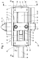
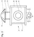
- FIG. 1 It can be seen there a lock 20 for fixing a container on a Vehicle chassis.
- the lock has a housing 21 a bottom wall 22, an upper wall 23, a front end wall 24, a rear end wall 25, a side wall 26 and one not visible in the figures because the side wall has been removed on the side 27 opposite the side wall 26, see Fig. 2.
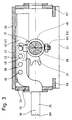
- a vertically directed pivot 28 arranged or stored, see in particular FIG. 3.
- a lower end 29 of the pivot 28 emerges from the bottom wall 22 down and serves to accommodate a transverse axial directed lever 30 for actuating the pivot pin 28.
- the lever 30 in a transverse bore 31 of the pivot 28 held in particular displaceable.
- a collar 32 is arranged on the top wall 23. This serves for receiving an upper end 33 of the pivot pin 28 upper end 33 connects a locking head 34. This reaches into a container corner fitting from below and secures it Container by turning 90 °. 1 to 3 show the Locking position of the pivot 28.
- the described Function of the pivot 28 and the interaction between Locking head 34, collar 32 and container corner fitting are known and need not be explained in more detail.
- a plug pin 35 is also mounted in the housing 21. This typically serves to secure a container with a so-called gooseneck tunnel on a gooseneck chassis and at a designated container corner fitting on the Front of container. After depositing the container on the Gooseneck chassis, the corner fitting is just in front of the lock 20, so that the plug pin 35 is inserted into the corner fitting can be. This will prevent the container from moving vertically secured. This is especially true during transportation empty container required.
- the function of the The plug is known for itself.
- the plug pin 35 is held displaceably in the housing 21.
- the plug pin 35 is therefore with an extension 38 running in the housing 21 provided, opposite to that emerging from the housing 21 End 39 of the plug pin 35 in the direction of one of the Sidewalls, in the present case towards the Sidewall 26 is cranked, but parallel to the end 39 runs.
- the plug pin 35 is in the region of the extension 38 Side wall 26 guided in a U-profile. This consists of two spaced legs 40, 41 and a corresponding area 42 of the side wall 26 between the Legs 40, 41. Inside the housing 21 is on the wall area 42 a sliding plate 43 made of slidable plastic or applied with a galvanized surface. Is advantageous in this area the reduction of sliding and static friction.
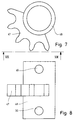
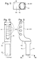
- the extension 38 has two superposed webs 44, 45, which by several, in the present case by four Round rods 46 are interconnected.
- the latter extend parallel to the axis of rotation 37 and are at a distance successively with the formation of a rack gear held between the webs 44, 45.
- the round bars 46 lie thus in a row parallel to the central axis 36.
- plug pin 35 and the pivot pin 28 gear connection there is one between the plug pin 35 and the pivot pin 28 gear connection, in this case formed by the described racket toothing of the extension 38 and a arranged on the pivot 28 gear segment 47, which over extends a pitch circle of approximately 125 °.
- the gear Connection is such that with a 90 ° rotation of the pivot 28 at the same time the desired pushing movement of the plug pin 35 takes place.
- the gear segment 47 is arranged on a sleeve 28, in particular welded, which are pushed onto the pivot 28 and through holes 49, 50 and corresponding bolts 51, 52 are secured on the pivot 28.
- the sleeve 48 extends almost over the entire inner height of the housing 21, so that the pivot 28 through the fixation the sleeve 48 is positioned on the pivot in the housing 21.
- the teeth of the Pivot 28 part of the same and stands in the radial direction not beyond the circumference of the pivot.
- the extension 38 then has a matching rack.
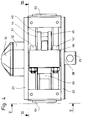
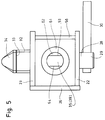
- FIGS. 4 to 6 show pivot 28 and plug 35 in retracted position or in a waiting position for the Picking up the respective container.
- the plug pin 35 is fully inserted into the housing 21.
- the oval locking head 34 is flush with the collar 32, see 4 and 5.
- the dimensions of the plug pin 35 including extension 38 is relative to the length of the Housing 21 dimensioned so that the plug pin 35 overall the side 27 can be inserted into the housing 21.
- the lever 30 can be analogous to the sleeve 48 via a corresponding one Sleeve inserted into the end 29 (not shown). Further Fastening types are conceivable.
- the end 39 of the plug pin emerging from the housing 21 35 has a round cross section with flats on both sides 53, 54.
- the movement of the plug pin 35 out of the housing 21 out is preferably limited by creating one in the area the offset angle piece 55 on the rear end wall 25th
- the end walls 24, 25 are constructed in a special way. So are either with a closed cover 60 (End wall 24) or have a cover 61 with a through hole 62 for the passage of the plug pin 35 (End wall 25). Instead of a lid, you can use the front wall also a position lamp, not shown, or a recording be used for this.
- the housing 21 is completely closed. dirt or dust cannot enter. To achieve one more The existing breakthroughs can provide better sealing Sealants must be secured, especially in the area of the passage the pivot 28 through the top wall 23 and / or bottom wall 22.
- the lock 20 shown is intended for assembly front right on the crossbar of a vehicle chassis.
- the Sidewall 26 is preferably laterally on the one not shown Crossbar welded on.
- the crossbar itself can do one have a closed cross-section. Cutouts for controls locking is not required. Accordingly, the crossbar retains after mounting the Lock 20 the required high stability.
- the housing 21 is constructed symmetrically overall. By reversed installation of the covers 60, 61 and corresponding others Installation of the plug pin 35, the lock 20 for prepared for installation on the left side of the vehicle chassis will. The removable side wall on side 27 is then again on the outside of the vehicle chassis.
- a piston-cylinder unit for actuating the pivot pin 28 in or on the housing 21 a piston-cylinder unit for actuating the pivot pin 28 arranged.
- a lever arrangement is then also preferred for connection between the pivot pin 28 and the piston-cylinder unit intended.
- the piston-cylinder unit can double-acting or with two piston-cylinder arrangements be constructed.
- a single-acting one is also possible Version with resetting by spring action.
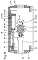
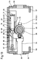
- FIGS. 12 and 13 Concrete formations of the idea of pneumatic Adjustment is shown in FIGS. 12 and 13.
- FIG. 12 is a double-acting cylinder 63 above the extension 38 of the Plug 35 arranged.
- a free end 64 of the cylinder 63 is over a bearing block 65 with the extension 38 (near the free end of the same) connected.
- a piston rod 66 emerges from the cylinder 63 on one side and is via a joint head with the housing, namely here with the rear end wall 25 connected.
- the movement of a piston 68 in the displacement 69 is controlled via air connections 70, 71 Compressed air supply to the connections 70, 71 and the continuation the air inside the cylinder 63 is not closer shown.
- connections 70, 71 flexible compressed air lines can be connected, which in turn via appropriate fixed connections in the housing walls from the Housing are brought out.
- Cylinder 63 and piston rod 66 can naturally also be interchanged so that the cylinder 63 with the end wall 25th and the piston rod via a bearing block with part of the Plug are connected.
- Cylinder 63 and piston rod 66 are in turn with the Plug pin 35 and the housing connected so that by Actuation of the cylinder 63 a movement of the plug pin 35 can be triggered. Reverse installation of cylinder 63 and piston rod 66, as previously with reference to FIG. 12 explained, possible.
- the external toothing 72 can be part of the double-acting Cylinder 63 or a cylinder 63 (not here shown) sleeve.
- the transverse forces that may occur are on one of the External teeth 72 opposite side of the cylinder 63 intercepted.
- pressure rollers 74, 75 on the Side wall 26 rotatably mounted.
- An outer wall 76 of the cylinder 63 rolls on movement of the same on the pressure rollers 74, 75.
Landscapes
- Engineering & Computer Science (AREA)
- Transportation (AREA)
- Mechanical Engineering (AREA)
- Lock And Its Accessories (AREA)
- Clamps And Clips (AREA)
- Pressure Vessels And Lids Thereof (AREA)
- Vehicle Step Arrangements And Article Storage (AREA)
Applications Claiming Priority (2)
| Application Number | Priority Date | Filing Date | Title |
|---|---|---|---|
| DE19720238 | 1997-05-14 | ||
| DE19720238A DE19720238A1 (de) | 1997-05-14 | 1997-05-14 | Verriegelung für Container an einem Fahrzeugchassis |
Publications (3)
| Publication Number | Publication Date |
|---|---|
| EP0878352A2 true EP0878352A2 (fr) | 1998-11-18 |
| EP0878352A3 EP0878352A3 (fr) | 1999-05-19 |
| EP0878352B1 EP0878352B1 (fr) | 2003-05-02 |
Family
ID=7829448
Family Applications (1)
| Application Number | Title | Priority Date | Filing Date |
|---|---|---|---|
| EP98108606A Expired - Lifetime EP0878352B1 (fr) | 1997-05-14 | 1998-05-12 | Dispositif de verrouillage pour un conteneur sur le châssis d'un véhicule |
Country Status (4)
| Country | Link |
|---|---|
| US (1) | US6092967A (fr) |
| EP (1) | EP0878352B1 (fr) |
| AT (1) | ATE238927T1 (fr) |
| DE (2) | DE19720238A1 (fr) |
Cited By (3)
| Publication number | Priority date | Publication date | Assignee | Title |
|---|---|---|---|---|
| WO2011113430A1 (fr) | 2010-03-16 | 2011-09-22 | 1. Rmm Entwicklungsgesellschaft Mbh & Co. Kg | Dispositif de verrouillage horizontal pour verrouiller un conteneur à ferrure d'angle sur une surface de chargement et procédé de verrouillage associé |
| EP3205604A1 (fr) * | 2016-02-09 | 2017-08-16 | Compact Container Systems LLC | Système et procédé pour bloquer les parois d'un conteneur |
| CN115285010A (zh) * | 2022-08-03 | 2022-11-04 | 中车眉山车辆有限公司 | 一种集装箱锁闭装置 |
Families Citing this family (12)
| Publication number | Priority date | Publication date | Assignee | Title |
|---|---|---|---|---|
| DE29903940U1 (de) * | 1999-03-04 | 1999-09-09 | R. Metternich Metallbau GmbH, 21107 Hamburg | Verriegelungseinrichtung für Container auf dem Chassis eines Fahrzeuges |
| KR100351793B1 (ko) * | 2000-01-27 | 2002-09-11 | 금명정밀공업 주식회사 | 트레일러용 컨테이너의 자동 록킹장치 |
| DE10108096A1 (de) * | 2001-02-19 | 2002-09-12 | Juergen Ehring | Verriegelungssystem für Fracht auf Fahrzeugen und seine Komponenten |
| US8490806B2 (en) * | 2009-09-01 | 2013-07-23 | Hyundai Translead | Cargo carrying container that can be interfaced with different chassis configurations |
| DE102014218891A1 (de) | 2014-09-19 | 2016-03-24 | Jost-Werke Gmbh | Verriegelungsvorrichtung für Container |
| US11987166B1 (en) * | 2020-03-17 | 2024-05-21 | Buffers Usa, Inc. | Remotely controlled twistlock assembly |
| US12017575B1 (en) * | 2020-03-18 | 2024-06-25 | Buffers Usa, Inc. | Swing latch locking assembly for height-adjustable twistlocks |
| DE102021112894A1 (de) * | 2021-05-18 | 2022-11-24 | Hamburger Patent Schmiede Gmbh | Containerverriegelungsvorrichtung sowie Containerverriegelungsverfahren |
| DE102021115027A1 (de) | 2021-06-10 | 2022-12-15 | Hamburger Patent Schmiede Gmbh | Absenkbare Containerverriegelung |
| DE102021122625A1 (de) | 2021-09-01 | 2023-03-02 | Hamburger Patent Schmiede Gmbh | Containerverriegelungsvorrichtung sowie Containerverriegelungsverfahren |
| WO2022268257A1 (fr) | 2021-06-23 | 2022-12-29 | Hamburger Patent Schmiede Gmbh | Dispositif de verrouillage de conteneur et procédé de verrouillage de conteneur |
| DE102021116280A1 (de) | 2021-06-23 | 2022-12-29 | Hamburger Patent Schmiede Gmbh | Containerverriegelungsvorrichtung sowie Containerverriegelungsverfahren |
Citations (1)
| Publication number | Priority date | Publication date | Assignee | Title |
|---|---|---|---|---|
| DE9114903U1 (de) | 1991-11-30 | 1993-03-25 | Schulz, Gerd, 34289 Zierenberg | Vorrichtung zur Verriegelung eines Containers an einem Fahrzeugchassis |
Family Cites Families (10)
| Publication number | Priority date | Publication date | Assignee | Title |
|---|---|---|---|---|
| US2439423A (en) * | 1942-12-21 | 1948-04-13 | Harlan D Fowler | Locking and safety signal combination for cargo airplanes |
| US3872555A (en) * | 1972-05-12 | 1975-03-25 | Value Engineering Company | Freight container coupler |
| US4023504A (en) * | 1976-03-29 | 1977-05-17 | Grey Vincent G | Flatbed car container sewing device |
| DE3038461A1 (de) * | 1980-10-11 | 1982-05-19 | Gerd Schulz Fahrzeug- und Container-Technik, 2100 Hamburg | Vorrichtung zum insbesondere stirnseitigen verriegeln von containern |
| US4352613A (en) * | 1980-11-10 | 1982-10-05 | Bertolini William A | Gear operated twist lock |
| US4352517A (en) * | 1980-11-10 | 1982-10-05 | Bertolini William A | Front locking pin for gooseneck container chassis |
| DE3940881A1 (de) * | 1989-07-04 | 1991-01-17 | Conver Osr Ozean Service Repar | Kuppelstueck zur loesbaren verbindung von containern |
| GB9508439D0 (en) * | 1994-06-25 | 1995-06-14 | Reynard Kenneth | Container clamping device |
| DE19606263A1 (de) * | 1995-03-22 | 1996-09-26 | Jost Werke Ag | Vorrichtung zur Verriegelung eines Containers an einem Fahrzeugchassis |
| DE19639988C2 (de) * | 1996-09-18 | 1998-06-25 | Mannesmann Ag | Automatische Verriegelung für Container, Wechselbehälter oder dergl. |
-
1997
- 1997-05-14 DE DE19720238A patent/DE19720238A1/de not_active Withdrawn
-
1998
- 1998-05-12 AT AT98108606T patent/ATE238927T1/de not_active IP Right Cessation
- 1998-05-12 EP EP98108606A patent/EP0878352B1/fr not_active Expired - Lifetime
- 1998-05-12 DE DE59808123T patent/DE59808123D1/de not_active Expired - Fee Related
- 1998-05-14 US US09/079,249 patent/US6092967A/en not_active Expired - Fee Related
Patent Citations (1)
| Publication number | Priority date | Publication date | Assignee | Title |
|---|---|---|---|---|
| DE9114903U1 (de) | 1991-11-30 | 1993-03-25 | Schulz, Gerd, 34289 Zierenberg | Vorrichtung zur Verriegelung eines Containers an einem Fahrzeugchassis |
Cited By (5)
| Publication number | Priority date | Publication date | Assignee | Title |
|---|---|---|---|---|
| WO2011113430A1 (fr) | 2010-03-16 | 2011-09-22 | 1. Rmm Entwicklungsgesellschaft Mbh & Co. Kg | Dispositif de verrouillage horizontal pour verrouiller un conteneur à ferrure d'angle sur une surface de chargement et procédé de verrouillage associé |
| EP3205604A1 (fr) * | 2016-02-09 | 2017-08-16 | Compact Container Systems LLC | Système et procédé pour bloquer les parois d'un conteneur |
| US10723507B2 (en) | 2016-02-09 | 2020-07-28 | Compact Container Systems, Llc | System and method for locking walls of a storage container |
| CN115285010A (zh) * | 2022-08-03 | 2022-11-04 | 中车眉山车辆有限公司 | 一种集装箱锁闭装置 |
| CN115285010B (zh) * | 2022-08-03 | 2024-04-26 | 中车眉山车辆有限公司 | 一种集装箱锁闭装置 |
Also Published As
| Publication number | Publication date |
|---|---|
| ATE238927T1 (de) | 2003-05-15 |
| DE19720238A1 (de) | 1998-11-19 |
| US6092967A (en) | 2000-07-25 |
| EP0878352B1 (fr) | 2003-05-02 |
| EP0878352A3 (fr) | 1999-05-19 |
| DE59808123D1 (de) | 2003-06-05 |
Similar Documents
| Publication | Publication Date | Title |
|---|---|---|
| EP0526522B1 (fr) | Fermeture a levier pivotant verrouillee par une serrure a pompe | |
| EP0878352B1 (fr) | Dispositif de verrouillage pour un conteneur sur le châssis d'un véhicule | |
| EP0178610B1 (fr) | Serrure | |
| DE3315779C2 (de) | Drucksteife Laschenkette | |
| EP0941889B1 (fr) | Dispositif d'extraction | |
| DE3628605C2 (fr) | ||
| DE19927654C1 (de) | Lamellendach für eine Dachöffnung eines Kraftfahrzeugs | |
| DE9214847U1 (de) | Drehriegelverschluß | |
| DE3412995C2 (de) | Spannrahmen für Kettenkratzförderer, insbesondere für Untertagebetriebe | |
| EP2143859B1 (fr) | Système de verouillage | |
| DE9412270U1 (de) | Verlegbare Brücke | |
| DE4106041C1 (fr) | ||
| DE19933576A1 (de) | Beschlag für Fenster oder Türen | |
| DE2430737B2 (de) | Drehtisch | |
| EP0844208A1 (fr) | Cric de véhicule | |
| EP0139046A1 (fr) | Agencement de porte ou de fenêtre coulissante | |
| DE9114903U1 (de) | Vorrichtung zur Verriegelung eines Containers an einem Fahrzeugchassis | |
| DE29601644U1 (de) | Auswechselbarer Zweischalengreifer | |
| CH602158A5 (en) | Filter press with movable cleaning appts. | |
| CH679232A5 (fr) | ||
| DE69718822T2 (de) | Fenster, insbesondere zum einbau in eine fassade, mit einer bedienungsvorrichtung und einer fensterbedienung | |
| DE19825071A1 (de) | Parallelausstellfenster mit Drehfunktion | |
| EP1019604B1 (fr) | Dispositif de fermeture dote d'une poignee horizontale | |
| DE9204436U1 (de) | An einer Decke o.dgl. aufhängbare Raumtrennwand sowie Rollenwagen hierfür | |
| DE4440925A1 (de) | Schubriegelschloß |
Legal Events
| Date | Code | Title | Description |
|---|---|---|---|
| PUAI | Public reference made under article 153(3) epc to a published international application that has entered the european phase |
Free format text: ORIGINAL CODE: 0009012 |
|
| AK | Designated contracting states |
Kind code of ref document: A2 Designated state(s): AT BE DE DK ES FI FR GB IE IT NL PT SE |
|
| AX | Request for extension of the european patent |
Free format text: AL;LT;LV;MK;RO;SI |
|
| PUAL | Search report despatched |
Free format text: ORIGINAL CODE: 0009013 |
|
| AK | Designated contracting states |
Kind code of ref document: A3 Designated state(s): AT BE CH CY DE DK ES FI FR GB GR IE IT LI LU MC NL PT SE |
|
| AX | Request for extension of the european patent |
Free format text: AL;LT;LV;MK;RO;SI |
|
| 17P | Request for examination filed |
Effective date: 19991103 |
|
| AKX | Designation fees paid |
Free format text: AT BE DE DK ES FI FR GB IE IT NL PT SE |
|
| GRAH | Despatch of communication of intention to grant a patent |
Free format text: ORIGINAL CODE: EPIDOS IGRA |
|
| GRAH | Despatch of communication of intention to grant a patent |
Free format text: ORIGINAL CODE: EPIDOS IGRA |
|
| GRAA | (expected) grant |
Free format text: ORIGINAL CODE: 0009210 |
|
| AK | Designated contracting states |
Designated state(s): AT BE DE DK ES FI FR GB IE IT NL PT SE |
|
| PG25 | Lapsed in a contracting state [announced via postgrant information from national office to epo] |
Ref country code: NL Free format text: LAPSE BECAUSE OF FAILURE TO SUBMIT A TRANSLATION OF THE DESCRIPTION OR TO PAY THE FEE WITHIN THE PRESCRIBED TIME-LIMIT Effective date: 20030502 Ref country code: IT Free format text: LAPSE BECAUSE OF FAILURE TO SUBMIT A TRANSLATION OF THE DESCRIPTION OR TO PAY THE FEE WITHIN THE PRESCRIBED TIME-LIMIT;WARNING: LAPSES OF ITALIAN PATENTS WITH EFFECTIVE DATE BEFORE 2007 MAY HAVE OCCURRED AT ANY TIME BEFORE 2007. THE CORRECT EFFECTIVE DATE MAY BE DIFFERENT FROM THE ONE RECORDED. Effective date: 20030502 Ref country code: IE Free format text: LAPSE BECAUSE OF NON-PAYMENT OF DUE FEES Effective date: 20030502 Ref country code: GB Free format text: LAPSE BECAUSE OF FAILURE TO SUBMIT A TRANSLATION OF THE DESCRIPTION OR TO PAY THE FEE WITHIN THE PRESCRIBED TIME-LIMIT Effective date: 20030502 Ref country code: FR Free format text: LAPSE BECAUSE OF NON-PAYMENT OF DUE FEES Effective date: 20030502 Ref country code: FI Free format text: LAPSE BECAUSE OF FAILURE TO SUBMIT A TRANSLATION OF THE DESCRIPTION OR TO PAY THE FEE WITHIN THE PRESCRIBED TIME-LIMIT Effective date: 20030502 |
|
| REG | Reference to a national code |
Ref country code: GB Ref legal event code: FG4D Free format text: NOT ENGLISH |
|
| PG25 | Lapsed in a contracting state [announced via postgrant information from national office to epo] |
Ref country code: AT Free format text: LAPSE BECAUSE OF NON-PAYMENT OF DUE FEES Effective date: 20030512 |
|
| PG25 | Lapsed in a contracting state [announced via postgrant information from national office to epo] |
Ref country code: BE Free format text: LAPSE BECAUSE OF NON-PAYMENT OF DUE FEES Effective date: 20030531 |
|
| REF | Corresponds to: |
Ref document number: 59808123 Country of ref document: DE Date of ref document: 20030605 Kind code of ref document: P |
|
| REG | Reference to a national code |
Ref country code: IE Ref legal event code: FG4D Free format text: GERMAN |
|
| PG25 | Lapsed in a contracting state [announced via postgrant information from national office to epo] |
Ref country code: SE Free format text: LAPSE BECAUSE OF FAILURE TO SUBMIT A TRANSLATION OF THE DESCRIPTION OR TO PAY THE FEE WITHIN THE PRESCRIBED TIME-LIMIT Effective date: 20030802 Ref country code: DK Free format text: LAPSE BECAUSE OF FAILURE TO SUBMIT A TRANSLATION OF THE DESCRIPTION OR TO PAY THE FEE WITHIN THE PRESCRIBED TIME-LIMIT Effective date: 20030802 |
|
| PG25 | Lapsed in a contracting state [announced via postgrant information from national office to epo] |
Ref country code: PT Free format text: LAPSE BECAUSE OF FAILURE TO SUBMIT A TRANSLATION OF THE DESCRIPTION OR TO PAY THE FEE WITHIN THE PRESCRIBED TIME-LIMIT Effective date: 20030804 |
|
| PG25 | Lapsed in a contracting state [announced via postgrant information from national office to epo] |
Ref country code: ES Free format text: LAPSE BECAUSE OF FAILURE TO SUBMIT A TRANSLATION OF THE DESCRIPTION OR TO PAY THE FEE WITHIN THE PRESCRIBED TIME-LIMIT Effective date: 20030813 |
|
| NLV1 | Nl: lapsed or annulled due to failure to fulfill the requirements of art. 29p and 29m of the patents act | ||
| GBV | Gb: ep patent (uk) treated as always having been void in accordance with gb section 77(7)/1977 [no translation filed] |
Effective date: 20030502 |
|
| BERE | Be: lapsed |
Owner name: *SANNE DIETER Effective date: 20030531 Owner name: *MILKEREIT HANS-ECKART Effective date: 20030531 |
|
| PG25 | Lapsed in a contracting state [announced via postgrant information from national office to epo] |
Ref country code: DE Free format text: LAPSE BECAUSE OF NON-PAYMENT OF DUE FEES Effective date: 20031202 |
|
| REG | Reference to a national code |
Ref country code: IE Ref legal event code: FD4D Ref document number: 0878352E Country of ref document: IE |
|
| PLBE | No opposition filed within time limit |
Free format text: ORIGINAL CODE: 0009261 |
|
| STAA | Information on the status of an ep patent application or granted ep patent |
Free format text: STATUS: NO OPPOSITION FILED WITHIN TIME LIMIT |
|
| 26N | No opposition filed |
Effective date: 20040203 |
|
| EN | Fr: translation not filed |