EP0878568A2 - Enrouleur de nappe - Google Patents
Enrouleur de nappe Download PDFInfo
- Publication number
- EP0878568A2 EP0878568A2 EP98810403A EP98810403A EP0878568A2 EP 0878568 A2 EP0878568 A2 EP 0878568A2 EP 98810403 A EP98810403 A EP 98810403A EP 98810403 A EP98810403 A EP 98810403A EP 0878568 A2 EP0878568 A2 EP 0878568A2
- Authority
- EP
- European Patent Office
- Prior art keywords
- belt
- winding device
- winding
- deflection rollers
- cotton
- Prior art date
- Legal status (The legal status is an assumption and is not a legal conclusion. Google has not performed a legal analysis and makes no representation as to the accuracy of the status listed.)
- Granted
Links
Images


Classifications
-
- D—TEXTILES; PAPER
- D01—NATURAL OR MAN-MADE THREADS OR FIBRES; SPINNING
- D01G—PRELIMINARY TREATMENT OF FIBRES, e.g. FOR SPINNING
- D01G27/00—Lap- or sliver-winding devices, e.g. for products of cotton scutchers, jute cards, or worsted gill boxes
- D01G27/04—Lap- or sliver-winding devices, e.g. for products of cotton scutchers, jute cards, or worsted gill boxes with automatic discharge of lap-roll or the like
Definitions
- the invention relates to a winding device for producing a cotton roll, where the cotton is on one of a continuous endless belt driven core, which is rotatable about an axis in an intermediate two deflection rollers formed, increasing with increasing wadding Loop of the belt tensioned by a tensioning device is arranged.
- This shift has a particularly disadvantageous effect when using side windows in the area of the winding loop. That means through the side Moving a layer is the distance of the cotton wool to the side guide discs reduced, which allows the edge areas of the cotton to fold.
- the invention is based on the object of the disadvantages mentioned eliminate, and propose a device for winding to use a winding to be able to produce even and clean edges.
- the belt be profiled at least on one side is provided, which with a profiled surface of the deflection rollers - transverse to Seen the direction of transport of the belt - forms a form-fitting guide.
- this profiling - in the belt longitudinal direction and in Seen circumferential direction of the pulleys - have the shape of a rack.
- This profiling means that - seen in the longitudinal direction of the belt - groove-shaped elevations or depressions are present. So that the profiling of Belts and pulley can interlock, these are groove-shaped Elevations or depressions shifted in the axial direction over the circumference of the Deflection pulleys arranged.
- the shapes of the rack-shaped profile can have different geometries. It would also be conceivable that the belt or the pulleys are only profiled in the edge area. Also seen across the width of the belt, different profiles or There are geometries for the profile.
- the belt be provided with openings is in which elevations of the deflection rollers engage at time intervals, the Elevations in the circumferential direction of the deflecting rollers are arranged such that at least one elevation is always engaged during the belt movement.
- the belt can be perforated in the edge area and in the longitudinal direction be provided, in which engage the elevations on the pulleys are attached.
- the pulleys and rotatably mounted with these gears the Engage teeth in the openings or perforations of the belt.
- Such Guided tours are e.g. used in the alien area of printers at which are provided for the purpose of feeding a continuous paper gears, which in Intervene in perforations of a continuous paper.
- the strap be over his Longitudinally distributed guide elements is provided, which during the belt movement communicate formally with leadership elements in time intervals that are rotatably connected to the pulleys.
- the belt is advantageously guided over more than two deflecting rollers, wherein for the purpose of lateral stabilization of the belt it is proposed that the belt is positively guided at least with three deflection rollers.
- the driven core is rotatably supported about a fixed axis.
- the attached winding disks are preferably arranged concentrically to the core.
- the axial distance between the pulleys and the belt should not be more than 5 mm. 1 to 2 mm can preferably be selected for this distance. Further advantages are described and shown in more detail with reference to the following description and exemplary embodiments.
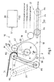
- FIG. 1 shows a winding device 10 for a purely schematic illustration Generation of a cotton roll 12.
- winding devices are used to roll up a fleece, a pile or a wad of fiber material into a wrap, before the fiber material is subjected to further treatment. So it can Winding device e.g. in a comb for picking up one from a drafting system leaking, supplied via dustpan, calender rollers and / or the like Serve nonwoven, the generated wrap then a combing machine Combing is presented.
- the following is in connection with the fed
- fiber material is only referred to as cotton wool, which is not the case restrictive sense.
- a cotton wool 14 is fed to the winding device 10 via a cotton wool feed 16, which in the present case is formed by a sheet metal bent at the outlet end is.
- the cotton wool 14 is wound on a core H serving as a core fixed axis A is rotatably mounted.
- This sleeve H is rotating from one Endless belt 18 driven by one between two pulleys R1, R2 Loop 20 is formed in which the sleeve H is received.
- the wadding 12 is counter-clockwise by the belt 18 driven, as indicated by the arrow F.
- the the wad of cotton looping loop 20 of the belt 18 becomes with increasing wadding 12 larger, the belt 18 during the entire winding process by a Tensioning device 22 is tensioned.
- This tensioning device 22 comprises one Tensioner pulley R4 with assigned linear guide 24.
- the belt 18 is on further pulleys R3 and R5 and along the Linear guide 24 adjustable tension pulley R4 so that it runs over the tension pulley R4 in a plane that is parallel to the axes of the two pulleys Level containing R1, R2.
- Fig. 1 is the axis along which the tension roller R4 is adjustable, referred to as the X axis.
- the deflection rollers R1, R2, R3, R5, the tension roller R4 and the sleeve H have the same diameter.
- the axes of the rollers and the sleeves are parallel to one another.
- the ones above Deflection rollers R1, R2 are at a vertical distance from the further deflection roller R5 and the tension pulley R4, which is larger than the maximum diameter of the Cotton wrap 12 is.
- the rollers R1, R2, R4 and R5 are thus arranged in a trapezoidal shape, wherein the horizontal distance between the rollers R4 and R5 larger than that between the Roles R1 and R2 is.
- the roller position R4 takes its left end position. Starting from this left end position of the tensioning roller R4 is the other one arranged above it Deflection pulley R3 shifted to the left by an amount from center to center measured approximately equal to the radius of the same diameter Corresponds to roles R1-R5.
- the vertical distance between the rollers R3, R4 corresponds measured from center to center about the roll diameter. This ensures that the belt 18, regardless of its position, the tensioning roller R4 always with a Wrap angle of 180 ° surrounds.
- the belt 18 is not closer to one Drive shown driven via the pulley R5, which is in the plane in which the belt 18 is tensioned.
- the left upper pulley R2 is at the upper end a pivot lever 26 attached to the other end about the axis of the left lower guide roller R5 is pivotally mounted.
- Fig. 1 is with dash-dotted lines Lines the position of the pivot lever 26 pivoted out to the left, in the full wad of cotton 12 is ejected.
- the sleeve H rotatable about the fixed axis A and the two deflection rollers R1, R2 are dimensioned in this way and when pivoted to the right into the working position Swivel arm 26 is arranged relative to one another so that the belt 18 Loop 20 formed between the pulleys R1, R2, the sleeve H at the beginning of Wrapping process with an initially minimal wrap angle that is greater than 180 °.
- This course of the loop 20 is at the beginning of the winding process represented by dotted lines in FIG.
- the tensioner pulley R4 their right end position.
- the Wrap angle with which the loop 20 surrounds the sleeve is larger.
- the Tensioner roller R4 is shifted to the left until it 12 after the cotton roll is completed has reached the left end position shown with solid lines.
- the tensioning device 22 is used to generate a dependent on the winding diameter Clamping force coupled to a preferably electronic control device 28.
- a direct Sensor 30 detecting the winding diameter is provided, which of the control device 28 delivers a corresponding signal S.
- the sleeve H is expediently between two winding disks 32, 34 (FIG. 2) clamped, which are removable laterally in the direction of the arrows.
- the winding disks 32, 34 are provided with lugs 36, 38 on which the sleeve is attachable.
- the deflection roller R1 has a circumference grooved profile 44 provided with the teeth 13 of the unilateral profile 9th of the belt 18 in the region of the deflection a positive connection transverse to Belt transport direction takes.
- the deflection roller R1 is shown uncut.
- the profile 9 of the shown in section Belt 18 has a rack-shaped design in cross section.
- the three outer layers of cotton 14 are shown by way of example Width on both sides by the dimension a over the width of the deflection roller R1 extends, whereby it bears against the end face 39 of the winding disk 32 or 33 is coming.
- the cotton web 14 is compressed, causing it to become can only expand in width until it abuts the end face 39 is coming. This slight expansion around dimension a is a desired effect, especially since this results in a certain compression and smoothing of the edge area of the Cotton web 14 takes place in cooperation with the winding disks 32, 33.
- the Proposed positive connection between the pulley R1 and the Belt 18 ensures that dimension a maintains a constant value. Without this lateral guidance would cause the belt to drift sideways unwanted upsets in the edge area, which can partially detach Fibers in this area.
- the profile are a variety of geometric designs possible. It would also be conceivable only in each case To provide such a profiling at the edge region of the belt or the deflection roller. The profile can be even or uneven on both sides extend the central axis MA.
- Fig. 4 shows a further embodiment, wherein the belt in the edge area with successively arranged openings 34 is provided, in which teeth 35 engage can, distributed according to the distance b over the circumference of the deflection roller R1 are.
- Fig. 6 a further embodiment is shown, the belt on the holder 52 a chain 49 is attached.
- the brackets 52 are connected via fastening means 53 (e.g. Rivets) attached to the belt and are attached to the link chain 49 via the web 51.
- the chain links 50 are at the webs 51 at a predetermined distance attached.
- a gear 46 is fixed on the outside coaxially to the deflection roller R1 attached, the teeth 47 in the individual chain links 50 for lateral fixation can intervene.
- the belt 18 is in the range of Deflection roller R1 guided laterally.
- the other deflection rollers R2, R3, R5 can also be used such devices may be provided around the belt in the deflection to lead positively across the direction of transport.
- the cotton wool 14 is fed over the cotton wool feed 16 and over a guide element 40 introduced into the loop 20 in the area 42 between the deflection rollers R1, R2.
- the diameter of the wound increases Cotton wrap 12 until it has reached a corresponding size, which is due to the sensor 30 of the control device 28 is reported.
- This is then used for Ejection mechanism triggered, the deflection roller R2 over the swivel lever 26 pivoted downward and releases the wrap for ejection.
- the winding disks 32 and 33 to the outside moved, whereby the winding can be removed from the winding position.
- a new sleeve is inserted into the diaper bag 20 after the Deflection roller R2 has been pivoted back into its winding position.
- the pod will then tensioned by moving the winding disks 32 and 33 together, see above that the system is ready for the formation of a new wrap. Further Details of the wrap formation can e.g. from the published DE-195 39 365 can be removed.
Landscapes
- Engineering & Computer Science (AREA)
- Textile Engineering (AREA)
- Preliminary Treatment Of Fibers (AREA)
- Replacement Of Web Rolls (AREA)
Applications Claiming Priority (2)
| Application Number | Priority Date | Filing Date | Title |
|---|---|---|---|
| DE19720825 | 1997-05-16 | ||
| DE19720825A DE19720825A1 (de) | 1997-05-16 | 1997-05-16 | Bandwickler |
Publications (3)
| Publication Number | Publication Date |
|---|---|
| EP0878568A2 true EP0878568A2 (fr) | 1998-11-18 |
| EP0878568A3 EP0878568A3 (fr) | 1999-06-16 |
| EP0878568B1 EP0878568B1 (fr) | 2002-03-20 |
Family
ID=7829830
Family Applications (1)
| Application Number | Title | Priority Date | Filing Date |
|---|---|---|---|
| EP98810403A Expired - Lifetime EP0878568B1 (fr) | 1997-05-16 | 1998-05-05 | Enrouleur de nappe |
Country Status (4)
| Country | Link |
|---|---|
| EP (1) | EP0878568B1 (fr) |
| JP (1) | JPH10325022A (fr) |
| CN (1) | CN1107130C (fr) |
| DE (2) | DE19720825A1 (fr) |
Cited By (2)
| Publication number | Priority date | Publication date | Assignee | Title |
|---|---|---|---|---|
| DE10332711A1 (de) * | 2002-10-25 | 2004-08-05 | Maschinenfabrik Rieter Ag | Riemen für Wickelvorrichtung |
| EP2055815A2 (fr) | 2007-10-31 | 2009-05-06 | Maschinenfabrik Rieter Ag | Courroie pour dispositif d'enroulement |
Families Citing this family (6)
| Publication number | Priority date | Publication date | Assignee | Title |
|---|---|---|---|---|
| DE10058299A1 (de) * | 2000-11-23 | 2002-05-29 | Rieter Ag Maschf | Vorrichtung zum Herstellen von Wattewickeln |
| CH701610A2 (de) | 2009-08-14 | 2011-02-15 | Rieter Ag Maschf | Vorrichtung zur Überwachung und Steuerung des Riemenverlaufes bei einer Vorrichtung zum Erzeugen eines Wattewickels. |
| CN104153057A (zh) * | 2014-07-22 | 2014-11-19 | 扬中市金德纺织机械设备厂 | 一种用于精梳准备的条卷机 |
| DE102016109535B4 (de) * | 2016-05-24 | 2018-10-11 | TRüTZSCHLER GMBH & CO. KG | Streckanlage für textile Faserbänder |
| JP6547964B2 (ja) * | 2016-06-17 | 2019-07-24 | 株式会社豊田自動織機 | ラップ巻取り装置 |
| CN120986796B (zh) * | 2025-10-21 | 2025-12-23 | 泰州市茂泰卫生用品有限公司 | 一种夹纸棉卷毡用捆绑缠绕线膜设备及其使用方法 |
Family Cites Families (5)
| Publication number | Priority date | Publication date | Assignee | Title |
|---|---|---|---|---|
| DE910754C (de) * | 1950-01-23 | 1954-05-06 | Tmm Research Ltd | Wickelvorrichtung fuer Textilmaschinen |
| DE1874436U (de) * | 1962-12-22 | 1963-06-20 | Adolf Bockemuehl Fa | Frotteur bzw. nitschelhose fuer spinnereimaschinen. |
| DE1289469B (de) * | 1963-02-23 | 1969-02-13 | Direzione Gruppo Brevetti | Nitschelhose von Krempeln |
| DE19539365A1 (de) * | 1995-10-23 | 1997-04-24 | Rieter Ag Maschf | Wickelvorrichtung |
| EP0770716A1 (fr) * | 1995-10-23 | 1997-05-02 | Maschinenfabrik Rieter Ag | Fabrication d'une mèche peignée |
-
1997
- 1997-05-16 DE DE19720825A patent/DE19720825A1/de not_active Withdrawn
-
1998
- 1998-05-05 DE DE59803401T patent/DE59803401D1/de not_active Expired - Fee Related
- 1998-05-05 EP EP98810403A patent/EP0878568B1/fr not_active Expired - Lifetime
- 1998-05-15 JP JP10134025A patent/JPH10325022A/ja active Pending
- 1998-05-15 CN CN98108462A patent/CN1107130C/zh not_active Expired - Fee Related
Cited By (3)
| Publication number | Priority date | Publication date | Assignee | Title |
|---|---|---|---|---|
| DE10332711A1 (de) * | 2002-10-25 | 2004-08-05 | Maschinenfabrik Rieter Ag | Riemen für Wickelvorrichtung |
| DE10332711B4 (de) * | 2002-10-25 | 2014-06-26 | Maschinenfabrik Rieter Ag | Riemen für Wickelvorrichtung |
| EP2055815A2 (fr) | 2007-10-31 | 2009-05-06 | Maschinenfabrik Rieter Ag | Courroie pour dispositif d'enroulement |
Also Published As
| Publication number | Publication date |
|---|---|
| CN1199783A (zh) | 1998-11-25 |
| DE59803401D1 (de) | 2002-04-25 |
| EP0878568A3 (fr) | 1999-06-16 |
| CN1107130C (zh) | 2003-04-30 |
| DE19720825A1 (de) | 1998-11-19 |
| EP0878568B1 (fr) | 2002-03-20 |
| JPH10325022A (ja) | 1998-12-08 |
Similar Documents
| Publication | Publication Date | Title |
|---|---|---|
| DE2721881C2 (de) | Wickelmaschine für Papierbahnen | |
| DE102005008705B3 (de) | Vorrichtung zum Zuführen von Faserbändern zu einer Wirkmaschine | |
| EP0799337B1 (fr) | Dispositif d'enroulement | |
| DE2503423A1 (de) | Verfahren und vorrichtung zum oeffnen eines fadenkabels | |
| DE1927863C3 (de) | Quertäfler zum Querlegen von kardiertem Faserflor | |
| DE2848058C2 (de) | Glasfasermatten in Form von Spinnvliesen | |
| EP2157216B1 (fr) | Dispositif destiné à la pose d'un voile | |
| EP1947223A1 (fr) | Dispositf pour le transport guidé d'un voile de fibres | |
| EP0878568B1 (fr) | Enrouleur de nappe | |
| DE19630922A1 (de) | Wickelvorrichtung | |
| DE3804147A1 (de) | Vorrichtung zur umformung eines grossformatigen flors, bestehend aus einer textilfasermasse, in ein faserband geringer breite, insbesondere fuer einen flachkaemmer | |
| DE1809663C3 (de) | Nadelmaschine zur Herstellung endloser Faser oder Haarvhese bzw bander | |
| EP0365856B1 (fr) | Dispositif de courroie transversal à la sortie d'une machine de cardage | |
| CH695344A5 (de) | Vorrichtung mit einem Riemen zur Herstellung eines Wattewickels. | |
| DE2635200C2 (de) | Fadenzuführeinrichtung | |
| DE2458241A1 (de) | Verfahren und vorrichtung zum kardieren von vliesstoffen | |
| DE3025451A1 (de) | Friktions-offenendspinnverfahren und vorrichtung zum durchfuehren dieses verfahrens | |
| DE2633474B2 (de) | Vorrichtung zum Ablegen eines fadenförmigen Gutes bzw. eines Fadenkabels in einen Behälter o.dgl. endlos, oder in Form von Teilen begrenzter Länge | |
| DE3317368A1 (de) | Vorrichtung zum antrieb eines friktionsspinnaggregates | |
| DE2135706A1 (de) | Verfahren und Vorrichtung zum Liefern von Garn mit einer geregelten Garnspannung | |
| CH686675A5 (de) | Klemmstelle fuer Watte. | |
| DE2735898A1 (de) | Vorrichtung zur herstellung einer glasfaser-stapelfasermatte | |
| DE19524187B4 (de) | Stofflegemaschine mit einem Legewagen | |
| DE1510357C (de) | Streckwerk und Kalanderwalzenanordnung für Faserbänder | |
| EP1038065B1 (fr) | Dispositif de transfert |
Legal Events
| Date | Code | Title | Description |
|---|---|---|---|
| PUAI | Public reference made under article 153(3) epc to a published international application that has entered the european phase |
Free format text: ORIGINAL CODE: 0009012 |
|
| AK | Designated contracting states |
Kind code of ref document: A2 Designated state(s): CH DE IT LI |
|
| AX | Request for extension of the european patent |
Free format text: AL;LT;LV;MK;RO;SI |
|
| PUAL | Search report despatched |
Free format text: ORIGINAL CODE: 0009013 |
|
| AK | Designated contracting states |
Kind code of ref document: A3 Designated state(s): AT BE CH CY DE DK ES FI FR GB GR IE IT LI LU MC NL PT SE |
|
| AX | Request for extension of the european patent |
Free format text: AL;LT;LV;MK;RO;SI |
|
| 17P | Request for examination filed |
Effective date: 19990521 |
|
| AKX | Designation fees paid |
Free format text: CH DE IT LI |
|
| GRAG | Despatch of communication of intention to grant |
Free format text: ORIGINAL CODE: EPIDOS AGRA |
|
| GRAG | Despatch of communication of intention to grant |
Free format text: ORIGINAL CODE: EPIDOS AGRA |
|
| GRAH | Despatch of communication of intention to grant a patent |
Free format text: ORIGINAL CODE: EPIDOS IGRA |
|
| 17Q | First examination report despatched |
Effective date: 20010810 |
|
| GRAH | Despatch of communication of intention to grant a patent |
Free format text: ORIGINAL CODE: EPIDOS IGRA |
|
| GRAA | (expected) grant |
Free format text: ORIGINAL CODE: 0009210 |
|
| AK | Designated contracting states |
Kind code of ref document: B1 Designated state(s): CH DE IT LI |
|
| REG | Reference to a national code |
Ref country code: CH Ref legal event code: EP |
|
| REF | Corresponds to: |
Ref document number: 59803401 Country of ref document: DE Date of ref document: 20020425 |
|
| PLBE | No opposition filed within time limit |
Free format text: ORIGINAL CODE: 0009261 |
|
| STAA | Information on the status of an ep patent application or granted ep patent |
Free format text: STATUS: NO OPPOSITION FILED WITHIN TIME LIMIT |
|
| 26N | No opposition filed |
Effective date: 20021223 |
|
| PGFP | Annual fee paid to national office [announced via postgrant information from national office to epo] |
Ref country code: CH Payment date: 20060515 Year of fee payment: 9 |
|
| REG | Reference to a national code |
Ref country code: CH Ref legal event code: PL |
|
| PG25 | Lapsed in a contracting state [announced via postgrant information from national office to epo] |
Ref country code: CH Free format text: LAPSE BECAUSE OF NON-PAYMENT OF DUE FEES Effective date: 20070531 Ref country code: LI Free format text: LAPSE BECAUSE OF NON-PAYMENT OF DUE FEES Effective date: 20070531 |
|
| PGFP | Annual fee paid to national office [announced via postgrant information from national office to epo] |
Ref country code: DE Payment date: 20080523 Year of fee payment: 11 |
|
| PGFP | Annual fee paid to national office [announced via postgrant information from national office to epo] |
Ref country code: IT Payment date: 20080524 Year of fee payment: 11 |
|
| PG25 | Lapsed in a contracting state [announced via postgrant information from national office to epo] |
Ref country code: DE Free format text: LAPSE BECAUSE OF NON-PAYMENT OF DUE FEES Effective date: 20091201 |
|
| PG25 | Lapsed in a contracting state [announced via postgrant information from national office to epo] |
Ref country code: IT Free format text: LAPSE BECAUSE OF NON-PAYMENT OF DUE FEES Effective date: 20090505 |