EP0878576A1 - Dispositif de verrouillage de porte pour appareils électriques - Google Patents
Dispositif de verrouillage de porte pour appareils électriques Download PDFInfo
- Publication number
- EP0878576A1 EP0878576A1 EP19980107108 EP98107108A EP0878576A1 EP 0878576 A1 EP0878576 A1 EP 0878576A1 EP 19980107108 EP19980107108 EP 19980107108 EP 98107108 A EP98107108 A EP 98107108A EP 0878576 A1 EP0878576 A1 EP 0878576A1
- Authority
- EP
- European Patent Office
- Prior art keywords
- locking
- wedge
- opening
- locking pin
- lock
- Prior art date
- Legal status (The legal status is an assumption and is not a legal conclusion. Google has not performed a legal analysis and makes no representation as to the accuracy of the status listed.)
- Granted
Links
- 230000000903 blocking effect Effects 0.000 claims abstract description 21
- 230000033001 locomotion Effects 0.000 claims abstract description 21
- 238000003780 insertion Methods 0.000 claims description 65
- 230000037431 insertion Effects 0.000 claims description 65
- 230000007480 spreading Effects 0.000 claims description 62
- 238000003892 spreading Methods 0.000 claims description 62
- 238000006073 displacement reaction Methods 0.000 claims description 27
- 238000002347 injection Methods 0.000 claims description 2
- 239000007924 injection Substances 0.000 claims description 2
- 239000002991 molded plastic Substances 0.000 claims description 2
- 230000000295 complement effect Effects 0.000 claims 1
- 230000000284 resting effect Effects 0.000 claims 1
- 230000005540 biological transmission Effects 0.000 abstract description 9
- 230000007246 mechanism Effects 0.000 abstract description 4
- 210000002105 tongue Anatomy 0.000 description 15
- 238000005406 washing Methods 0.000 description 4
- 230000008901 benefit Effects 0.000 description 3
- 206010015137 Eructation Diseases 0.000 description 2
- 208000027687 belching Diseases 0.000 description 2
- 238000013461 design Methods 0.000 description 2
- 238000005516 engineering process Methods 0.000 description 2
- 210000003746 feather Anatomy 0.000 description 2
- 238000004519 manufacturing process Methods 0.000 description 2
- 238000000034 method Methods 0.000 description 2
- 208000027418 Wounds and injury Diseases 0.000 description 1
- 230000003213 activating effect Effects 0.000 description 1
- 230000004913 activation Effects 0.000 description 1
- 230000015572 biosynthetic process Effects 0.000 description 1
- 238000010276 construction Methods 0.000 description 1
- 230000006378 damage Effects 0.000 description 1
- 230000007547 defect Effects 0.000 description 1
- 230000001419 dependent effect Effects 0.000 description 1
- 238000011161 development Methods 0.000 description 1
- 230000018109 developmental process Effects 0.000 description 1
- 210000001061 forehead Anatomy 0.000 description 1
- 208000014674 injury Diseases 0.000 description 1
- 230000008569 process Effects 0.000 description 1
- 238000003860 storage Methods 0.000 description 1
- 238000003786 synthesis reaction Methods 0.000 description 1
- 238000012546 transfer Methods 0.000 description 1
Images


Classifications
-
- D—TEXTILES; PAPER
- D06—TREATMENT OF TEXTILES OR THE LIKE; LAUNDERING; FLEXIBLE MATERIALS NOT OTHERWISE PROVIDED FOR
- D06F—LAUNDERING, DRYING, IRONING, PRESSING OR FOLDING TEXTILE ARTICLES
- D06F37/00—Details specific to washing machines covered by groups D06F21/00 - D06F25/00
- D06F37/42—Safety arrangements, e.g. for stopping rotation of the receptacle upon opening of the casing door
-
- Y—GENERAL TAGGING OF NEW TECHNOLOGICAL DEVELOPMENTS; GENERAL TAGGING OF CROSS-SECTIONAL TECHNOLOGIES SPANNING OVER SEVERAL SECTIONS OF THE IPC; TECHNICAL SUBJECTS COVERED BY FORMER USPC CROSS-REFERENCE ART COLLECTIONS [XRACs] AND DIGESTS
- Y10—TECHNICAL SUBJECTS COVERED BY FORMER USPC
- Y10S—TECHNICAL SUBJECTS COVERED BY FORMER USPC CROSS-REFERENCE ART COLLECTIONS [XRACs] AND DIGESTS
- Y10S292/00—Closure fasteners
- Y10S292/69—Washing machine or stove closure latch
-
- Y—GENERAL TAGGING OF NEW TECHNOLOGICAL DEVELOPMENTS; GENERAL TAGGING OF CROSS-SECTIONAL TECHNOLOGIES SPANNING OVER SEVERAL SECTIONS OF THE IPC; TECHNICAL SUBJECTS COVERED BY FORMER USPC CROSS-REFERENCE ART COLLECTIONS [XRACs] AND DIGESTS
- Y10—TECHNICAL SUBJECTS COVERED BY FORMER USPC
- Y10T—TECHNICAL SUBJECTS COVERED BY FORMER US CLASSIFICATION
- Y10T292/00—Closure fasteners
- Y10T292/08—Bolts
- Y10T292/1043—Swinging
- Y10T292/1051—Spring projected
- Y10T292/1052—Operating means
- Y10T292/1061—Rigid
-
- Y—GENERAL TAGGING OF NEW TECHNOLOGICAL DEVELOPMENTS; GENERAL TAGGING OF CROSS-SECTIONAL TECHNOLOGIES SPANNING OVER SEVERAL SECTIONS OF THE IPC; TECHNICAL SUBJECTS COVERED BY FORMER USPC CROSS-REFERENCE ART COLLECTIONS [XRACs] AND DIGESTS
- Y10—TECHNICAL SUBJECTS COVERED BY FORMER USPC
- Y10T—TECHNICAL SUBJECTS COVERED BY FORMER US CLASSIFICATION
- Y10T292/00—Closure fasteners
- Y10T292/08—Bolts
- Y10T292/1043—Swinging
- Y10T292/1075—Operating means
- Y10T292/1078—Closure
-
- Y—GENERAL TAGGING OF NEW TECHNOLOGICAL DEVELOPMENTS; GENERAL TAGGING OF CROSS-SECTIONAL TECHNOLOGIES SPANNING OVER SEVERAL SECTIONS OF THE IPC; TECHNICAL SUBJECTS COVERED BY FORMER USPC CROSS-REFERENCE ART COLLECTIONS [XRACs] AND DIGESTS
- Y10—TECHNICAL SUBJECTS COVERED BY FORMER USPC
- Y10T—TECHNICAL SUBJECTS COVERED BY FORMER US CLASSIFICATION
- Y10T292/00—Closure fasteners
- Y10T292/08—Bolts
- Y10T292/1043—Swinging
- Y10T292/1075—Operating means
- Y10T292/1083—Rigid
- Y10T292/1084—Closure catch
-
- Y—GENERAL TAGGING OF NEW TECHNOLOGICAL DEVELOPMENTS; GENERAL TAGGING OF CROSS-SECTIONAL TECHNOLOGIES SPANNING OVER SEVERAL SECTIONS OF THE IPC; TECHNICAL SUBJECTS COVERED BY FORMER USPC CROSS-REFERENCE ART COLLECTIONS [XRACs] AND DIGESTS
- Y10—TECHNICAL SUBJECTS COVERED BY FORMER USPC
- Y10T—TECHNICAL SUBJECTS COVERED BY FORMER US CLASSIFICATION
- Y10T292/00—Closure fasteners
- Y10T292/42—Rigid engaging means
- Y10T292/432—Sliding catch
-
- Y—GENERAL TAGGING OF NEW TECHNOLOGICAL DEVELOPMENTS; GENERAL TAGGING OF CROSS-SECTIONAL TECHNOLOGIES SPANNING OVER SEVERAL SECTIONS OF THE IPC; TECHNICAL SUBJECTS COVERED BY FORMER USPC CROSS-REFERENCE ART COLLECTIONS [XRACs] AND DIGESTS
- Y10—TECHNICAL SUBJECTS COVERED BY FORMER USPC
- Y10T—TECHNICAL SUBJECTS COVERED BY FORMER US CLASSIFICATION
- Y10T292/00—Closure fasteners
- Y10T292/68—Keepers
- Y10T292/696—With movable dog, catch or striker
Definitions
- the invention relates to a door locking device for electrical devices, in particular household appliances, according to the preamble of claim 1.
- a door locking device is known from the EP-A-0 347 592, which also goes back to an invention by the local applicant.
- a lock is provided on the electrical device and a locking pin is provided on the device door.
- the locking pin is a lever pivotably mounted on a swivel joint. This lever carries a hook part at its end facing away from the swivel joint. With the hook part, the lever engages through a locking slide arranged longitudinally displaceably in the lock in an engagement opening.
- the rear side of the hook part forming the end face of the lever is designed as a guide bevel in order to move the locking slide into its closed position when the lever is inserted into the lock.
- the lever is spring-loaded to hold the lever with the hook part in the closed position.
- the hook part acts on the locking slide when the door is closed with the spring force and engages behind a correspondingly designed rear grip part on the lock.
- the disadvantage here is that the properly locked appliance door in the event of a defect Spring mechanism or opened from the inside only with a very high effort can be because of the lever-like locking pin with the hook part this must be destroyed.
- This is particularly disadvantageous for devices with a large size Recording volume, for example in washing machines with large drums. It cannot be ruled out that a child playing in such a way crawled in the big drum and then locked the door becomes. The child in the machine can then usually use the appliance door no longer open because it does not have sufficient forces around which the hook part to destroy the load-bearing locking pin.
- the inventive door locking device has one between its Opening and its closing position to be moved back and forth in the castle longitudinally mounted locking slide.
- This locking slide is in its closed position by means of a blocking device - like her for example from EP-A-0 347 592 is known - lockable. Only after activation This blocking device can start up the electrical device at all.
- the invention is based on the basic consideration of this blocking device as the actual one Locking device to use for device operation.
- the one in that Locked in the inventive door locking device when locked The locking pin that enters the device door therefore primarily serves as a mechanical one Prelock for the appliance door.
- the invention therefore makes Take advantage of the knowledge that the activated blocking device the locking slide so securely and reliably sets in its closed position that another Securing the appliance door is no longer necessary at all.
- the mechanical locking of the appliance door known from the prior art by means of a hook is in the inventive door locking device substituted by a between the locking slide and locking pin permanently effective transmission.
- This gear is designed so that the pin is always so positively guided that when the blocking device is deactivated and at the same time in the lock inserted pin each appliance door movement at the same time Sliding movement of the locking slide causes.
- the appliance door is attached by means of an outside Handle is moved properly or whether the appliance door, for example, from Device interior is pushed open.
- Even when belching is through the gear connection always between the locking pin and locking slide ensures that the locking slide when the blocking device is deactivated moves to its open position. This in turn ensures that, for example, a child who accidentally finds himself in a washing drum has always locked itself out of the device without outside help can free.
- Claims 2 to 11 referring back to claim 1 relate to a first one Embodiment of the door locking device with a between locking slide and locking pin permanently effective wedge thrust gear, while the dependent claims 12 to 17 relate to a second embodiment with one between the locking slide and locking pin effective cam gear.
- the locking pin In contrast to the previously known locking devices is the subject of claim 2, the locking pin usually fixed to the appliance door kinematically via a wedge-push mechanism with the locking slide coupled. Wedge thrust transmissions are known from, for example
- the locking pin is used as a pushing wedge to implement the wedge-push mechanism configured, which in a correspondingly designed keyway on Locking slide engages.
- the wedge thrust gear it is possible the movement in the direction of insertion of the locking pin when Lock the appliance door in the direction perpendicular to the direction of insertion Redirect the direction of movement of the locking slide.
- the locking slide moves from its open position when the appliance door is open in its closed position.
- the locking slide moved into the closed position is then in a known manner (EP-A-0 347 592) by means of a thermobimetal-controlled, electrical blocking device prevented in its Slide open position.
- This blocking device is only with activated when the electrical device is switched on.
- the blocking device serves also to release the locking slide with a time delay to ensure that revolving parts completely again before opening the appliance door have come to a standstill.
- thermobimetal-controlled blocking device since the electrical, thermobimetal-controlled blocking device only works with activated when the electrical device is switched on, it is possible to switch it off Device to open the device door from the inside with little effort, because the wedge thrust works equally in both directions of movement. Since the push wedge is positively guided in the wedge guide groove, the locking slide is also positively guided on the locking pin so that when belching the locking slide from the inside of the appliance door forcibly returns to its open position. In this way, an in a machine interior, for example a washing machine drum, accidentally child easily open the appliance door from the inside and out again free the machine.
- the centering bar provided according to the teaching of claim 6 can either be formed only on one wedge surface, but also on both wedge surfaces. Of the Centering bar centers the push wedge on the one hand when it is inserted into the wedge guide groove and on the other hand contributes to the fact that the elements of the wedge thrust transmission do not tilt against each other when closing the appliance door.
- Claims 7 to 9 relate to pre-locking the appliance door.
- the actual locking of the appliance door takes place by means of the electrical Blocking device of the locking slide in its closed position.
- the Pre-locking is intended to prevent the appliance door from springing open before it is switched on prevent the device.
- the embodiment according to claim 7 causes a loud snapping sound when the rollers fall into the grooves in the side surfaces of the push wedge.
- This acoustic signal for the operator that the appliance door has reached its closed position causes it to snap into place the roles in the grooves a clear snap feeling in the Hand of the operator.
- This pre-closure signals the correct one to the operator Lock the locking pin in the lock and at the same time the complete Moving the locking slide into its closed position.
- the overflow cone proposed in claim 9 has a double function. On the one hand, it favors the introduction of what is effective as a locking pin Thrust wedge in the lock.
- the two start on the cone cylindrical rollers rotate while the cone holds the two rollers stored leaf spring legs continuously spread apart before the rollers to some extent roll into the grooves.
- the same The force needed to slide the rolls into the grooves again be used so that the rollers rotate out of the grooves.
- the leaf spring leg drives the opening movement of the push wedge and thus serve as an additional drive for the locking slide from his Closed position to its open position. In this way, the roles support together with the leaf spring, the opening movement of the appliance door.
- claims 10 and 11 relate to an advantageous manufacturing technology Structure of the locking slide.
- the locking slide has one principally known from EP-A-0 347 592, rectangular opening. This opening is designed according to the invention as a bearing eye so that in it A slide is fixed in the final assembly state. In the sledge is the same Wedge guide groove molded in.
- the production technology is particularly advantageous Embodiment of the carriage according to claim 11 as inexpensive to produce Injection molded plastic part.
- the Sled simply inserted or snapped into the rectangular bearing eye are and is thus firmly connected to the locking slide.
- the second embodiment of the locking device according to the invention according to claims 12 to 17 is structurally closer to that of the Prior art (EP-A-0347 592) locking device known as that The first embodiment described above.
- a locking pin designed as a handlebar is provided.
- This Locking pin is pivotally mounted in a bearing block.
- a cam is provided in the locking pin according to claim 12. This cam engages in a scanning opening on the locking slide.
- This scanning opening is preferably analogous to the bearing eye in the locking slide designed according to claim 10.
- the locking slide also in this embodiment only a translational movement between its Can open position and its closed position, the locking pin not only invade the castle, but also by a certain amount Amount can be pivoted.
- This pivotability on the one hand and the geometry the cam disc, on the other hand, are so coordinated that also in this embodiment, a pulling or pushing movement exerted on the appliance door always implemented in a sliding movement of the locking slide becomes.
- the V-shaped design of the cam plate in turn causes the insertion the locking pin makes a clearly audible clicking sound as soon as the Locking pin by means of its front insertion slope through the insertion opening of the lock housing in the scanning opening in the locking slide is inserted at the moment when the apex of the V-shaped Cam is applied to the opening edge of the scanning opening.
- Words of the locking pin with its V-shaped cam disc like a touch finger on the edge of the scanning opening This one too Embodiment in turn act the locking slide on the one hand and the Locking pin on the other hand via a permanently engaged, positively driven gearbox together.
- independent claim 18 is independent of the claims 1 to 17 inventive door locking device.
- This locking device has an effective push lock when the appliance door is open the locking slide.
- This push lock effectively prevents the unwanted Moving the locking slide from its open position in its closed position when the appliance door is open.
- the locking slide is thus not manipulable from the outside, which ensures that rotating Parts in the electrical device can only be set in motion if the appliance door is also securely locked.
- the push lock is only by means of the locking pin usually attached to the appliance door can be detached. By the usual attachment of the locking pin on the appliance door and the The lock on the device is the locking slide fixed in the lock from the outside even more difficult to access and therefore more difficult to manipulate.
- the locking pin consequently has the double function of a locking part in this invention for the appliance door on the one hand and at the same time an unlocking part for the Push lock on the other hand.
- the subject matter of claim 18 is independent inventive from the subject matter of claims 1 to 17, however can be combined with all objects of the invention according to claims 1 to 17.
- Claims 19 and 20 relate to advantageous designs of the locking bolt the push lock.
- the end faces of spreading spring legs used as a locking pin The use of spread spring legs has the advantage that they are under high pretension at the locking stop and at the same time easily by an appropriately designed locking pin in their unlocked position can be brought to the locking slide to be able to move into its closed position when the appliance door is closed.
- Claims 21 to 23 relate in turn to an inventive synthesis of the subject matter of the invention of claim 2 and the claims related back to it 3 to 11 on the one hand and the subject matter of claim 18 and claims 19 and 20 referring back to him.
- the slide is not only effective as a groove carrier for the wedge guide groove, but also carries the stopper (s) for the push lock.
- Claim 22 relates to a special embodiment and arrangement of the spreading spring in the area of the wedge guide groove, causing an unwanted manipulation on Locking slide is even more difficult when the appliance door is open.
- Claim 23 finally teaches a double function of the overrun cone on the thrust wedge as an expansion cone and thus as an unlocking part for the push lock.
- Claim 24 relates to the combination of the subject matter of the claim 18 with the second embodiment of the transmission in the locking device according to claims 12 to 17.
- the locking pin 1 on his facing the appliance door, not shown in the drawings End of a mounting flange 2.
- Both the upper Wedge surface 3 and the lower wedge surface 4 are each divided into two by one in in each case their centering web 5.
- 4 extending side surfaces 6 of the locking pin 1 are still molded in grooves 7.
- the side surfaces 6 are finally beveled to form an overflow cone 8.
- the locking slide 9 is rectangular at one end Bearing eye 10 broken.
- a slide can be inserted into the bearing eye 10 11.
- a wedge guide groove 12 is formed in the slide 11.
- the wedge guide groove 12 in turn has a lower guide surface 13 and an upper one Guide surface 14.
- the lower guide surface 13 is flanked laterally by the Locking stops 15.
- the guide surfaces are analogous to the wedge surfaces 3, 4 13, 14 each divided in two by a centering centering slot 16.
- a leaf spring 21 is U-shaped such that its leaf spring legs 22 are rectangular are bent from the leaf spring body 23. At the ends 24 of the two leaf spring legs 22, a cylindrical roller 25 is rotatably supported.
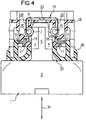
- lock housing is from the housing base 26 and that on the housing base 26 formed by means of the locking hook 27 snap-on housing cover 28.
- Housing cover 28 To fix the housing cover 28 on the housing base 26 engage on Housing cover 28 molded locking hooks 27 in corresponding locking recesses 29 on the housing base 26.
- FIG. 2 the two that form the keyway groove 12 can be seen Guide surfaces 13, 14.
- the lower guide surface 13 and the upper guide surface 14 of the keyway groove 12 run parallel to each other. Opposite the direction of displacement 31 of the locking slide 9 they are at an angle of 30 ° inclined.
- the of the guide surfaces 13, 14 together with the Wedge surfaces 3, 4 formed web guide consequently has a direction of displacement 31 at an angle of 30 ° extending web guiding 32.
- the locking device works as follows: The locking pin 1 is inserted into the insertion opening 33 left open in the housing base 26 in the insertion direction 34 which is perpendicular to the direction of displacement 31.
- the locking pin 1 slides with the surfaces of its centering webs 5 at the opening edges 35 of the insertion opening 33.
- the locking pin 1 is consequently positively guided in the insertion opening 33 in such a way that it cannot be displaced in the direction of displacement 31 which is perpendicular to the insertion direction 34.
- the wedge surfaces 3, 4 forming the thrust wedge of the wedge thrust transmission then grip in the wedge guide groove 12 such that the upper wedge surface 3 on the upper Guide surface 14 and correspondingly the lower wedge surface 4 on the lower Wedge surface 13 rests.
- the Baffle cone 8 When inserting the locking pin 1 into the insertion opening 33 the Baffle cone 8 immediately on the cylindrical, at the ends 24 of the leaf spring legs 22 rotatably mounted rollers 25. Spreads due to its conical shape the run-up cone 38 continuously separates the leaf spring legs 22 so that he continues in the direction of insertion 34 between the rollers 25 or the leaf spring legs 22 can intervene. In its complete closed position shown in FIG. 3 are the rollers 25 completely overflowed over the cone 8 and are snapped into the grooves 7 in the side surfaces 6 of the locking pin 1.
- the rollers 25 also have a second function. As soon as the rollers 25 run up again on the run-up cone 8 when the locking pin 1 is pulled out, the leaf spring legs 22 tend to move resiliently towards one another, as a result of which the rollers 25 are rolled on the run-up cone 8 and thus push the locking pin 1 out of the insertion opening 33 and press on the appliance door at the same time. This is shown by curve II drawn in dashed lines in FIG. 8.
- the force denoted by F R represents the force exerted by the rollers 25, which act as pressure rollers when the appliance door is opened, on the run-up cone 8 in the direction opposite to the insertion force vector 36.
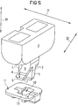
- the locking pin 51 pivotally mounted in a bearing block 52.
- the bearing block 52 is in turn attached to the appliance door, not shown in Fig. 9.
- the bearing block 52 is penetrated by two through holes 53. Through the through holes 53 fastening screws can be inserted, which are in turn screwed into the appliance door, not shown in the drawing.
- the locking pin 51 With its bearing end 54, the locking pin 51 is pivotable about the hub 55 stored in the bearing block 52 against the spring pressure of the leg spring 56.
- the Leg spring 56 is supported here with its short spring leg 57 in the end of the bearing 54 of the locking pin 51. With its long spring leg 58 is the leg spring 56 in the bearing block 52 or against that not shown in the drawing Device door relocated.
- the pin end face 59 faces away from the bearing end 54 in the insertion direction 34.
- From the side surface of the locking pin adjoining the end face 59 51 is the V-shaped cam 60 in cross-section in the direction of displacement 31 from.
- the region of the cam disk adjacent to the pin end face 59 60, which forms the outside of a V-leg, is the run-in slope 61.
- the inlet slope 61 facing away from the insertion direction 34 second V-leg of the V-shaped cross section of the cam 60 forming Sliding guide slope 62.
- the inlet slope 61 and the sliding guide slope 62 both open into the apex edge 63.
- To the inlet slope 61 and the sliding guide slope 62 the side surfaces 64 of the locking pin run vertically 51.
- the grooves 65 are in turn molded into the side surfaces 64.
- the side surfaces 64 run in the area between the pin face 59 and the Grooves 65 conical to favor the entry of the locking pin 51 in the castle.
- the lock slider 69 is at one end from the rectangular scan opening 70 broken. At least those transverse to the direction of displacement 31 extending opening edges 71 of the scanning opening 70 are bent out at right angles to form the protruding at right angles from the locking slide 59 Guide tongues 72. Also shown is the incidence backdrop 73 in the Drawings not shown blocking device (similarly present in the locking slide 9 acc. Fig. 1).
- the spreading spring legs 77 of the spreading spring 78 are provided with offsets 79.
- the spreading spring 78 is mounted in the lock housing to the locking slide 69 located in its open position arranged that the offsets 79 in the insertion direction 34 above the scanning opening 70 come to rest and protrude laterally into the scanning opening 70 (Fig. 13).
- the spreading spring legs act on their spreading spring end faces 80 77 here the adjacent guide tongue 72 of the locking slide 69 and thus inhibit a displacement of the locking slide 69 in the displacement direction 31
- the lock housing is formed from the housing base 66 and that on the Housing bottom 66 by means of locking hooks 67 snap-on housing cover 68 Fixing the housing cover 68 on the housing base 67 engage the housing cover 68 molded locking hooks 67 in corresponding locking recesses 74 on the housing base 66.
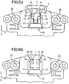
- FIG. 10 shows the Lock slide 69 open position. In this open position align the scanning opening 70 of the locking slide 69 on the one hand and the On the other hand, insertion opening 75 of the housing base. The insertion opening 75 and the scanning opening 70 are thus congruent and are in this locking slide position also congruent with each other.
- the spreading spring end faces 80 which on the in the Drawing right guide tongue 72 and so the longitudinal displacement of the locking slide 69 in the displacement direction 31.
- the locking slide 69 is therefore locked in its open position.
- Fig. 10 can also be seen the locking pin 51, which with its Entry slope 61 abuts the edge of the insertion opening 75.
- This edge of the insertion opening 75 is designed like a funnel and thus forms an insertion funnel 76.
- the V shape of the inlet slope 61 which can be seen clearly in FIG. Sliding guide bevel 62 and vertex 63 essentially existing cam 60.
- Fig. 12 which is the front view of the illustration in FIG. 11 according to direction arrow XII shows, that is to say the representation of FIG Axis of the insertion direction 34 rotated by 90 °, it can be seen that the spreading spring end faces 80 in this position is still the same as in the illustration of the Fig. 11 arranged guide tongue 72 bear blocking. With their bends 79, the spreading spring 78 lies in the grooves 65 on the locking pin 51 a. The position corresponding to the representation in FIGS. 11 and 12 the spreading spring 78 is shown in Fig. 13. Fig. 13 shows a bottom view of the Insertion opening 75, but without a locking pin. Fig. 13 thus corresponds to the View of the lock with the appliance door open.
- FIG. 14 corresponds to the perspective of Fig. 11.
- the locking pin 51 completely in the castle.
- the locking slide 69 is too from its opening position shown in FIG. 11 in the direction of displacement 31 in move its closed position.
- FIG. 15 shows the front view analogously to FIG. 12 according to direction arrow XV in FIG. 14.
- FIG. 16 again shows the bottom view the insertion opening 75.
- this is again the locking pin 51, which is absolutely necessary in reality, has been omitted.
- the lack of resistance of the spreading spring end face 80 is the displaceability of the locking slide 69 in its displacement direction 31.
- the apex edge 63 acts originally not acted upon by the spreading spring end faces 80, in FIG. 11 and 14 guide tongue 72 shown on the left at the opening edge 71 of the scanning opening 70.
- the apex edge 63 is consequently effective as a cam 60, that due to the spring pressure they the locking slide in the direction of displacement 31 moves into its closed position, which is shown in Fig. 14.
- FIG. 17 shows the closed position of the locking slide 69, which also in Fig. 14 is shown. However, FIG. 17 shows the same section plane as FIG. 10 of the sectional representations according to FIGS. 17, 18 and 19 is the transmission kinematics explained in more detail when opening the appliance door.
- the cam 60 In the closed position of the Locking slide 69, the cam 60 is completely in the scanning opening 70 of the locking slide 69.
- the locking pin 51 is in swung back its starting position. Is that not shown in the drawings Blocking device is deactivated and a train on the bearing block Exercised 52 connected door, the locking pin 51 slides with the Sliding guide bevel 62 along the edge of the introduction funnel 76.
- the locking pin 51 can be removed its position shown in FIG. 19 simply into its starting position shown in FIG. 10 are pulled out of the lock, the top edge slides 63 of the cam 60 first on the one shown in FIG. 19 on the left Down the guide tongue to then along the insertion funnel 76 from the Sliding out the lock.
Landscapes
- Engineering & Computer Science (AREA)
- Textile Engineering (AREA)
- Casings For Electric Apparatus (AREA)
- Lock And Its Accessories (AREA)
- Electric Ovens (AREA)
- Control Of Vending Devices And Auxiliary Devices For Vending Devices (AREA)
Applications Claiming Priority (4)
| Application Number | Priority Date | Filing Date | Title |
|---|---|---|---|
| DE19718219 | 1997-04-30 | ||
| DE19718219 | 1997-04-30 | ||
| DE19815591 | 1998-04-08 | ||
| DE19815591A DE19815591A1 (de) | 1998-04-08 | 1998-04-08 | Türverriegelungsvorrichtung für elektrische Geräte |
Publications (2)
| Publication Number | Publication Date |
|---|---|
| EP0878576A1 true EP0878576A1 (fr) | 1998-11-18 |
| EP0878576B1 EP0878576B1 (fr) | 2003-07-02 |
Family
ID=26036193
Family Applications (1)
| Application Number | Title | Priority Date | Filing Date |
|---|---|---|---|
| EP19980107108 Expired - Lifetime EP0878576B1 (fr) | 1997-04-30 | 1998-04-18 | Dispositif de verrouillage de porte pour appareils électriques |
Country Status (4)
| Country | Link |
|---|---|
| US (1) | US6145898A (fr) |
| EP (1) | EP0878576B1 (fr) |
| AT (1) | ATE244330T1 (fr) |
| DE (1) | DE59808870D1 (fr) |
Cited By (4)
| Publication number | Priority date | Publication date | Assignee | Title |
|---|---|---|---|---|
| WO2006064070A1 (fr) * | 2004-12-17 | 2006-06-22 | Girbau, Sa | Dispositif de fermeture pour porte d'appareil pourvu d'un tambour rotatif et verrou utilise dans ledit dispositif |
| ITTO20090077A1 (it) * | 2009-02-05 | 2010-08-06 | Illinois Tool Works | Dispositivo bloccaporta per un elettrodomestico con incaglio mobile |
| US8246089B2 (en) | 2006-10-28 | 2012-08-21 | Marquardt Gmbh | Lock for a household appliance |
| US11174581B2 (en) * | 2017-07-13 | 2021-11-16 | Emz-Hanauer Gmbh & Co. Kgaa | Overlifting door latch with locking mechanism |
Families Citing this family (23)
| Publication number | Priority date | Publication date | Assignee | Title |
|---|---|---|---|---|
| FR2798120B1 (fr) * | 1999-09-03 | 2001-11-16 | Citec Environnement | Dispositif automatique par gravite de verrouillage/ deverrouillage du couvercle d'un bac et bac equipe d'un tel dispositif |
| US6612625B1 (en) * | 2000-09-11 | 2003-09-02 | Genesis Technical Marketing, Inc. | Case locking system |
| US6527315B2 (en) * | 2000-12-22 | 2003-03-04 | Whirlpool Corporation | Door latch for a dishwasher |
| KR100452354B1 (ko) * | 2002-01-09 | 2004-10-12 | 엘지전자 주식회사 | 드럼세탁기의 도어 후크 어셈블리 |
| KR20040105342A (ko) * | 2003-06-07 | 2004-12-16 | 삼성전자주식회사 | 세탁기 |
| ITMI20070575A1 (it) * | 2007-03-22 | 2008-09-23 | Elettrotecnica Rold Srl | Dispositivo di bloccaggio del portello di chiusura di macchine lavabiancheria e asciugabiancheria |
| ITMI20070601A1 (it) * | 2007-03-26 | 2008-09-27 | Elettrotecnica Rold Srl | Dispositivo di bloccaggio del portello di chiusura di lavatrici |
| FI120415B (fi) * | 2007-04-27 | 2009-10-15 | Abloy Oy | Ovenlukko |
| US20080276925A1 (en) * | 2007-05-11 | 2008-11-13 | Griswold Kevin L | Latch for oven door |
| ATE538348T1 (de) * | 2007-06-01 | 2012-01-15 | Electrolux Home Prod Corp | BACKOFEN MIT EINER SCHLIEßVORRICHTUNG |
| US8317236B2 (en) * | 2008-04-16 | 2012-11-27 | Electrolux Home Products, Inc. | Appliance drawer and latch mechanism therefor |
| DE102009019225B4 (de) * | 2008-04-30 | 2016-06-09 | Lg Electronics Inc. | Maschine zum Behandeln von Textil- und Lederwaren |
| DE202010000032U1 (de) * | 2010-01-13 | 2011-03-10 | Krones Ag | Verriegelungsvorrichtung und Sicherungseinrichtung für einen Arbeitsbereich einer Maschine |
| DE102010031750B4 (de) * | 2010-07-21 | 2012-07-12 | Eads Deutschland Gmbh | Lösbare Verbindungsanordnung zur Anbringung vo abwerfbaren Außenlasten an einem Luftfahrzeug |
| ITRM20110118A1 (it) * | 2011-03-15 | 2012-09-16 | Bitron Spa | Dispositivo blocco-porta con apertura a pulsante. |
| ITTO20110569A1 (it) * | 2011-06-29 | 2012-12-30 | Bitron Spa | Dispositivo di bloccaggio e sbloccaggio del portello di un apparecchio elettrodomestico |
| EP3066279B1 (fr) * | 2013-11-04 | 2018-04-11 | Illinois Tool Works Inc. | Pêne de verrouillage d'appareil |
| US9957657B2 (en) * | 2015-01-30 | 2018-05-01 | Emz-Hanauer Gmbh & Co. Kgaa | Appliance lock |
| US11272826B2 (en) * | 2017-06-23 | 2022-03-15 | Illinois Tool Works Inc. | Appliance door latch system with pre-latching catch alignment system |
| IT201800004000A1 (it) * | 2018-03-27 | 2019-09-27 | Illinois Tool Works | Blocco-porta per elettrodomestici, in particolare lavatrici e simili, con meccanismo di riduzione di forza perfezionato |
| US20200115927A1 (en) * | 2018-10-16 | 2020-04-16 | Hti Technology And Industries, Inc. | Appliance lock with magnetic sensing switch actuation in a hydrophobic enclosure |
| US12351972B2 (en) * | 2018-11-29 | 2025-07-08 | Illinois Tool Works Inc. | Door lock and electronic apparatus |
| CN112941831B (zh) * | 2021-03-26 | 2024-12-17 | 金羚电器有限公司 | 一种滑扣组件、门锁、洗衣机门及洗衣机 |
Citations (3)
| Publication number | Priority date | Publication date | Assignee | Title |
|---|---|---|---|---|
| DE3426738A1 (de) * | 1984-07-20 | 1986-01-30 | Ymos Aktiengesellschaft Industrieprodukte, 6053 Obertshausen | Tuerverschluss, insbesondere fuer eine haushaltsmaschine |
| EP0347592A1 (fr) * | 1988-05-28 | 1989-12-27 | Ellenberger & Poensgen GmbH | Dispositif de verrouillage de porte pour appareils électriques |
| EP0481503A1 (fr) * | 1990-10-17 | 1992-04-22 | Zanker GmbH | Verrouillage de porte pour appareil ménager |
Family Cites Families (14)
| Publication number | Priority date | Publication date | Assignee | Title |
|---|---|---|---|---|
| US1909753A (en) * | 1930-12-25 | 1933-05-16 | Maxwell Steel Vault Company | Lid-lock for burial caskets |
| US2001443A (en) * | 1934-03-02 | 1935-05-14 | Williams Harry | Automobile doorlock |
| US2842075A (en) * | 1954-08-11 | 1958-07-08 | Gen Motors Corp | Door fastener |
| US3617957A (en) * | 1968-12-12 | 1971-11-02 | Texas Instruments Inc | Locking devices for washing machines or electromechanical appliances with bimetallic element |
| US3701617A (en) * | 1971-01-12 | 1972-10-31 | Concrete Pipe Machinery Co | Lock assembly for connecting a vibrating core of a concrete pipe making machine |
| BE791863A (fr) * | 1971-11-26 | 1973-03-16 | Rocchitelli Onofrio | Appareil pour le verrouillage et le deverrouillage temporise dedispositifs de fermeture de portes de machines |
| IT994158B (it) * | 1973-08-21 | 1975-10-20 | Texas Instruments Italia Spa | Dispositivo di bloccaggio con interruttore ritardatore termico ad azionamento voltmetrico per sportelli |
| FR2261398B1 (fr) * | 1974-02-20 | 1976-11-26 | Peugeot & Renault | |
| US4262945A (en) * | 1979-04-27 | 1981-04-21 | Inglis Limited | Safety latch for washer closure |
| US4609233A (en) * | 1983-11-03 | 1986-09-02 | Timberline Supply, Ltd. | Furniture locking system |
| DE3430414A1 (de) * | 1984-08-18 | 1986-02-27 | Ellenberger & Poensgen Gmbh, 8503 Altdorf | Tuerverriegelungsvorrichtung mit sofortverriegelung und verzoegerter entriegelung mit wasserstandsueberwachung |
| DE3605960A1 (de) * | 1986-02-25 | 1987-08-27 | Ymos Ag Ind Produkte | Tuerverschluss fuer haushaltsmaschinen |
| IT1202431B (it) * | 1987-01-27 | 1989-02-09 | Onofrio Rocchitelli | Dispositivo per il bloccaggio rapido e lo sbloccaggio ritardato dei dispositivi di chiusura di portelli di macchine aventi nell'interno parti soggette a rotazione inerziale in particolare per portelli di macchine lavabiancheria |
| DE59006871D1 (de) * | 1989-04-13 | 1994-09-29 | Ellenberger & Poensgen | Sicherheits-Türschloss für Türen von Elektrogeräten. |
-
1998
- 1998-04-18 AT AT98107108T patent/ATE244330T1/de active
- 1998-04-18 EP EP19980107108 patent/EP0878576B1/fr not_active Expired - Lifetime
- 1998-04-18 DE DE59808870T patent/DE59808870D1/de not_active Expired - Lifetime
- 1998-04-30 US US09/069,943 patent/US6145898A/en not_active Expired - Fee Related
Patent Citations (3)
| Publication number | Priority date | Publication date | Assignee | Title |
|---|---|---|---|---|
| DE3426738A1 (de) * | 1984-07-20 | 1986-01-30 | Ymos Aktiengesellschaft Industrieprodukte, 6053 Obertshausen | Tuerverschluss, insbesondere fuer eine haushaltsmaschine |
| EP0347592A1 (fr) * | 1988-05-28 | 1989-12-27 | Ellenberger & Poensgen GmbH | Dispositif de verrouillage de porte pour appareils électriques |
| EP0481503A1 (fr) * | 1990-10-17 | 1992-04-22 | Zanker GmbH | Verrouillage de porte pour appareil ménager |
Cited By (9)
| Publication number | Priority date | Publication date | Assignee | Title |
|---|---|---|---|---|
| WO2006064070A1 (fr) * | 2004-12-17 | 2006-06-22 | Girbau, Sa | Dispositif de fermeture pour porte d'appareil pourvu d'un tambour rotatif et verrou utilise dans ledit dispositif |
| ES2255851A1 (es) * | 2004-12-17 | 2006-07-01 | Girbau, S.A. | Dispositivo de cierre para puerta de aparato provisto de bombo giratorio, y pestillo aplicable a tal dispositivo. |
| ES2255851B1 (es) * | 2004-12-17 | 2007-03-16 | Girbau, S.A. | Dispositivo de cierre para puerta de aparato provisto de bombo giratorio, y pestillo aplicable a tal dispositivo. |
| US8016328B2 (en) | 2004-12-17 | 2011-09-13 | Girbau S.A. | Locking device for the door of an apparatus comprising a rotary drum, and a latch for such device |
| US8246089B2 (en) | 2006-10-28 | 2012-08-21 | Marquardt Gmbh | Lock for a household appliance |
| ITTO20090077A1 (it) * | 2009-02-05 | 2010-08-06 | Illinois Tool Works | Dispositivo bloccaporta per un elettrodomestico con incaglio mobile |
| WO2010091019A1 (fr) * | 2009-02-05 | 2010-08-12 | Illinois Tool Works Inc. | Dispositif de serrure de porte pour appareil domestique électrique avec loquet mobile |
| US8702134B2 (en) | 2009-02-05 | 2014-04-22 | Illinois Tool Works Inc. | Door lock device for an electric household appliance with movable latch |
| US11174581B2 (en) * | 2017-07-13 | 2021-11-16 | Emz-Hanauer Gmbh & Co. Kgaa | Overlifting door latch with locking mechanism |
Also Published As
| Publication number | Publication date |
|---|---|
| US6145898A (en) | 2000-11-14 |
| EP0878576B1 (fr) | 2003-07-02 |
| DE59808870D1 (de) | 2003-08-07 |
| ATE244330T1 (de) | 2003-07-15 |
Similar Documents
| Publication | Publication Date | Title |
|---|---|---|
| EP0878576B1 (fr) | Dispositif de verrouillage de porte pour appareils électriques | |
| DE112016006079T5 (de) | Fahrzeug-türverriegelungssystem | |
| EP0105176A2 (fr) | Elément de liaison pour un câble de changement de vitesse | |
| DE4032565A1 (de) | Vorrichtung zum loesbaren verbinden zweier bauteile | |
| DE102007045177A1 (de) | Verriegelungsvorrichtung | |
| DE112016006099T5 (de) | Fahrzeug-türverriegelungssystem | |
| WO2010023126A1 (fr) | Dispositif pour verrouiller et déverrouiller le volet d'obturation d’un récipient | |
| WO2000012851A2 (fr) | Serrure a pene demi-tour faisant saillie hors du boitier de ladite serrure | |
| EP0893718A1 (fr) | Douille en particulier pour une connexion optique et connecteur pour fibres optiques | |
| EP0481503A1 (fr) | Verrouillage de porte pour appareil ménager | |
| DE102020206094A1 (de) | Verriegelungsvorrichtung sowie schiebetüranlage | |
| EP3913181B1 (fr) | Élément de blocage de portière pourvu d'un support amovible | |
| EP1224881A1 (fr) | Boucle de ceinture de sécurité | |
| EP1355022A2 (fr) | Dispositif d'actionnement pour la serrure d'une porte, d'un capot ou similaires, notamment pour un véhicule | |
| DE102007025723B3 (de) | Kupplungseinheit für ein Garagentor, insbesondere Kipp-, Schwenk- oder Sektionaltor | |
| DE2355656C2 (de) | Elektrische Steckverbindungsvorrichtung | |
| DE69401213T2 (de) | Schlüssel mit zwei abschrägungen am ende für ein sicherheitzylinderschloss und zylinderschloss dafür | |
| DE19815591A1 (de) | Türverriegelungsvorrichtung für elektrische Geräte | |
| EP2085543B1 (fr) | Serrure | |
| EP2317047A2 (fr) | Agencement de ferrure | |
| EP0752328B1 (fr) | Attelage de remorque | |
| DE9104766U1 (de) | Antipaniktürschloß | |
| DE102021201084B4 (de) | Koppeleinrichtung zur kraftübertragenden Verbindung von Bowdenzügen und Bowdenzuganordnung | |
| EP1992772B1 (fr) | Agencement de ferrure | |
| DE102008016317B4 (de) | Schloss mit einer Anordnung zur Fallendrehung |
Legal Events
| Date | Code | Title | Description |
|---|---|---|---|
| PUAI | Public reference made under article 153(3) epc to a published international application that has entered the european phase |
Free format text: ORIGINAL CODE: 0009012 |
|
| AK | Designated contracting states |
Kind code of ref document: A1 Designated state(s): AT CH DE IT LI |
|
| AX | Request for extension of the european patent |
Free format text: AL;LT;LV;MK;RO;SI |
|
| 17P | Request for examination filed |
Effective date: 19981215 |
|
| AKX | Designation fees paid |
Free format text: AT CH DE IT LI |
|
| 17Q | First examination report despatched |
Effective date: 20001117 |
|
| GRAG | Despatch of communication of intention to grant |
Free format text: ORIGINAL CODE: EPIDOS AGRA |
|
| GRAG | Despatch of communication of intention to grant |
Free format text: ORIGINAL CODE: EPIDOS AGRA |
|
| GRAH | Despatch of communication of intention to grant a patent |
Free format text: ORIGINAL CODE: EPIDOS IGRA |
|
| GRAH | Despatch of communication of intention to grant a patent |
Free format text: ORIGINAL CODE: EPIDOS IGRA |
|
| GRAA | (expected) grant |
Free format text: ORIGINAL CODE: 0009210 |
|
| AK | Designated contracting states |
Designated state(s): AT CH DE IT LI |
|
| REG | Reference to a national code |
Ref country code: CH Ref legal event code: EP |
|
| REF | Corresponds to: |
Ref document number: 59808870 Country of ref document: DE Date of ref document: 20030807 Kind code of ref document: P |
|
| REG | Reference to a national code |
Ref country code: CH Ref legal event code: NV Representative=s name: DR. LUSUARDI AG |
|
| PLBE | No opposition filed within time limit |
Free format text: ORIGINAL CODE: 0009261 |
|
| STAA | Information on the status of an ep patent application or granted ep patent |
Free format text: STATUS: NO OPPOSITION FILED WITHIN TIME LIMIT |
|
| 26N | No opposition filed |
Effective date: 20040405 |
|
| REG | Reference to a national code |
Ref country code: CH Ref legal event code: PFA Owner name: ELLENBERGER & POENSGEN GMBH Free format text: ELLENBERGER & POENSGEN GMBH#INDUSTRIESTRASSE 2-8#D-90518 ALTDORF (DE) -TRANSFER TO- ELLENBERGER & POENSGEN GMBH#INDUSTRIESTRASSE 2-8#D-90518 ALTDORF (DE) |
|
| PGFP | Annual fee paid to national office [announced via postgrant information from national office to epo] |
Ref country code: DE Payment date: 20110426 Year of fee payment: 14 Ref country code: CH Payment date: 20110421 Year of fee payment: 14 |
|
| PGFP | Annual fee paid to national office [announced via postgrant information from national office to epo] |
Ref country code: AT Payment date: 20110418 Year of fee payment: 14 |
|
| PGFP | Annual fee paid to national office [announced via postgrant information from national office to epo] |
Ref country code: IT Payment date: 20110426 Year of fee payment: 14 |
|
| REG | Reference to a national code |
Ref country code: CH Ref legal event code: PL |
|
| REG | Reference to a national code |
Ref country code: AT Ref legal event code: MM01 Ref document number: 244330 Country of ref document: AT Kind code of ref document: T Effective date: 20120418 |
|
| PG25 | Lapsed in a contracting state [announced via postgrant information from national office to epo] |
Ref country code: AT Free format text: LAPSE BECAUSE OF NON-PAYMENT OF DUE FEES Effective date: 20120418 Ref country code: LI Free format text: LAPSE BECAUSE OF NON-PAYMENT OF DUE FEES Effective date: 20120430 Ref country code: CH Free format text: LAPSE BECAUSE OF NON-PAYMENT OF DUE FEES Effective date: 20120430 |
|
| REG | Reference to a national code |
Ref country code: DE Ref legal event code: R119 Ref document number: 59808870 Country of ref document: DE Effective date: 20121101 |
|
| PG25 | Lapsed in a contracting state [announced via postgrant information from national office to epo] |
Ref country code: IT Free format text: LAPSE BECAUSE OF NON-PAYMENT OF DUE FEES Effective date: 20120418 |
|
| PG25 | Lapsed in a contracting state [announced via postgrant information from national office to epo] |
Ref country code: DE Free format text: LAPSE BECAUSE OF NON-PAYMENT OF DUE FEES Effective date: 20121101 |