EP0879108B1 - Geschliffener schneideeinsatz - Google Patents
Geschliffener schneideeinsatz Download PDFInfo
- Publication number
- EP0879108B1 EP0879108B1 EP97904708A EP97904708A EP0879108B1 EP 0879108 B1 EP0879108 B1 EP 0879108B1 EP 97904708 A EP97904708 A EP 97904708A EP 97904708 A EP97904708 A EP 97904708A EP 0879108 B1 EP0879108 B1 EP 0879108B1
- Authority
- EP
- European Patent Office
- Prior art keywords
- grinding
- ground
- insert
- cutting
- cutting insert
- Prior art date
- Legal status (The legal status is an assumption and is not a legal conclusion. Google has not performed a legal analysis and makes no representation as to the accuracy of the status listed.)
- Expired - Lifetime
Links
- 238000005520 cutting process Methods 0.000 title claims abstract description 62
- 238000000227 grinding Methods 0.000 claims abstract description 44
- 238000003754 machining Methods 0.000 claims abstract description 3
- 239000002184 metal Substances 0.000 claims abstract 2
- 239000000843 powder Substances 0.000 claims description 6
- 238000005245 sintering Methods 0.000 claims description 5
- 238000000034 method Methods 0.000 claims description 4
- 238000004519 manufacturing process Methods 0.000 claims description 3
- 230000007704 transition Effects 0.000 abstract description 3
- 239000000463 material Substances 0.000 description 5
- 238000003825 pressing Methods 0.000 description 4
- 238000003801 milling Methods 0.000 description 3
- 238000007493 shaping process Methods 0.000 description 2
- 230000001154 acute effect Effects 0.000 description 1
- 238000001816 cooling Methods 0.000 description 1
- 229910003460 diamond Inorganic materials 0.000 description 1
- 239000010432 diamond Substances 0.000 description 1
- 238000005553 drilling Methods 0.000 description 1
- 230000000694 effects Effects 0.000 description 1
- 230000002349 favourable effect Effects 0.000 description 1
- 239000012535 impurity Substances 0.000 description 1
- 238000003780 insertion Methods 0.000 description 1
- 230000037431 insertion Effects 0.000 description 1
- 239000002245 particle Substances 0.000 description 1
- 230000002093 peripheral effect Effects 0.000 description 1
- 230000003014 reinforcing effect Effects 0.000 description 1
- 230000000717 retained effect Effects 0.000 description 1
Images
Classifications
-
- B—PERFORMING OPERATIONS; TRANSPORTING
- B24—GRINDING; POLISHING
- B24B—MACHINES, DEVICES, OR PROCESSES FOR GRINDING OR POLISHING; DRESSING OR CONDITIONING OF ABRADING SURFACES; FEEDING OF GRINDING, POLISHING, OR LAPPING AGENTS
- B24B7/00—Machines or devices designed for grinding plane surfaces on work, including polishing plane glass surfaces; Accessories therefor
- B24B7/10—Single-purpose machines or devices
- B24B7/16—Single-purpose machines or devices for grinding end-faces, e.g. of gauges, rollers, nuts, piston rings
- B24B7/17—Single-purpose machines or devices for grinding end-faces, e.g. of gauges, rollers, nuts, piston rings for simultaneously grinding opposite and parallel end faces, e.g. double disc grinders
-
- B—PERFORMING OPERATIONS; TRANSPORTING
- B23—MACHINE TOOLS; METAL-WORKING NOT OTHERWISE PROVIDED FOR
- B23B—TURNING; BORING
- B23B27/00—Tools for turning or boring machines; Tools of a similar kind in general; Accessories therefor
- B23B27/14—Cutting tools of which the bits or tips or cutting inserts are of special material
- B23B27/141—Specially shaped plate-like cutting inserts, i.e. length greater or equal to width, width greater than or equal to thickness
-
- B—PERFORMING OPERATIONS; TRANSPORTING
- B24—GRINDING; POLISHING
- B24B—MACHINES, DEVICES, OR PROCESSES FOR GRINDING OR POLISHING; DRESSING OR CONDITIONING OF ABRADING SURFACES; FEEDING OF GRINDING, POLISHING, OR LAPPING AGENTS
- B24B3/00—Sharpening cutting edges, e.g. of tools; Accessories therefor, e.g. for holding the tools
- B24B3/60—Sharpening cutting edges, e.g. of tools; Accessories therefor, e.g. for holding the tools of tools not covered by the preceding subgroups
-
- B—PERFORMING OPERATIONS; TRANSPORTING
- B23—MACHINE TOOLS; METAL-WORKING NOT OTHERWISE PROVIDED FOR
- B23B—TURNING; BORING
- B23B2200/00—Details of cutting inserts
- B23B2200/24—Cross section of the cutting edge
- B23B2200/247—Cross section of the cutting edge sharp
-
- B—PERFORMING OPERATIONS; TRANSPORTING
- B23—MACHINE TOOLS; METAL-WORKING NOT OTHERWISE PROVIDED FOR
- B23B—TURNING; BORING
- B23B2222/00—Materials of tools or workpieces composed of metals, alloys or metal matrices
- B23B2222/28—Details of hard metal, i.e. cemented carbide
-
- B—PERFORMING OPERATIONS; TRANSPORTING
- B23—MACHINE TOOLS; METAL-WORKING NOT OTHERWISE PROVIDED FOR
- B23B—TURNING; BORING
- B23B2226/00—Materials of tools or workpieces not comprising a metal
- B23B2226/31—Diamond
Definitions
- the present invention relates to a ground cutting insert according to claim 1, a sharp edge being obtained with maintained chip geometry.
- the cutting insert is primarily intended for milling, although also cutting inserts for turning and drilling lie within the framework of the invention.
- Cutting inserts such as indexable inserts are made by form pressing and sintering of a cutting material forming powder.
- the formed cutting material is usually cemented carbide.
- the cutting insert comprises an upper surface or chip surface, a bottom surface being substantially plane-parallel with the former surface (these two surfaces constitute the main surfaces) and being abuttable against a co-operating bottom support surface in an insert seat, and side or relief surfaces extending between these two surfaces, of which side or relief surfaces at least one is abuttable against a co-operating side support surface in the insert seat.
- the side surfaces may be perpendicular to said upper and bottom surfaces, but usually they are somewhat obliquely positioned, in an acute angle to the upper surface and in an obtuse angle to the bottom surface, at least one transition between the upper surface and a side surface being shaped as a cutting edge.
- a direct pressing method is being applied to an increasing extent, according to which method a cemented carbide forming powder first is shaped into the desired form in a pressing tool adapted for the purpose, and thereafter it is given the final strength by sintering in an oven.
- the pressing operation as such has been refined and is today so rational that it brings about good possibilities of forming the cutting edge and the appurtenant chip shaping surfaces and possible reinforcing faces with great accuracy.
- contour grinding or peripheral grinding which consists in that the surface(s) that adjoins to the individual cutting edge is after-ground in a step after grinding and cooling. This contour grinding is made on the relief side of the cutting insert, i.e., on the side surfaces.
- US-A-5 078 550 on wich is based the preamble of claim 1, is referred to.
- the working measure or the IC measure is altered.
- the cutting insert has sintered-in chip breakers, when grinding, the primary land of the cutting insert may become unacceptably narrow and fragile.
- the bottom surface of the cutting inserts have been ground to a substantially perfect planarity, in order to guarantee a safe and stable support in the insert seat.
- a primary object of the present invention is to provide a cutting insert that may be ground with a substantially unaltered chip cutting geometry on the rake side as well as on the relief side.
- a second object of the invention is to be capable of producing sharp cutting edges without altering the chip cutting geometry.
- Still another object of the present invention is to rationalize the grinding of the cutting inserts as much as possible.
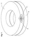
- Fig 1 shows in a stylized form two individually rotatable grinding plates I and 2 of conventional type, which are used for the grinding of inter alia cutting inserts, such as, e.g., indexable cutting inserts of a square basic shape.
- cutting inserts such as, e.g., indexable cutting inserts of a square basic shape.
- the upper plate 1 and the lower plate 2 are coated with a diamond powder.
- a cutting insert 3, whose upper and/or bottom surface are to be ground, are retained firmly between the grinding plates by means of a perforated insert holder or tray, whose thickness is less than the thickness of the cutting inserts. A part of this tray is illustrated by means of the cutout detail 4.
- both plates may be rotated simultaneously, whereby the opposed upper and bottom surfaces are ground simultaneously, which constitutes the optimal and most favourable grinding manner, from a production-technical point of view.
- the two plates are suitably rotated in opposite directions. If the ground surface is larger on the one side, the grinding plate on that side may be rotated correspondingly faster.
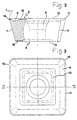
- Figures 2 and 3 illustrate a square positive cutting inserts according to the present invention. It has an upper surface 5, a bottom surface 6 and four side surfaces 7. The transitions between the four side surfaces 7 may as such be sharp but consist preferably of rounded corner portions 17.
- the relief angle i.e., the angle between a side surface 7 and the normal for the upper and lower surfaces, may be between 0 and +40°, preferably between +5 and +30°.
- it may have a through centre hole 8 for the insertion of a suitable clamping device, such as lock screw (not shown).
- a centre hole as such is not necessary, in view of the fact that the cutting insert may also be fastened by other means, such as, for instance, by means of a clamp or a wedge.
- the upper surface of the cutting insert has a sintered-in chip breaker 9, which results in a more positive and a more light-cutting geometry.
- This may for instance be made in the form of an uninterrupted, circumferential depression, such as shown in fig 3.
- Adjacent to the main cutting edge 10 is the primary land 11, whose width b is less than 1 mm, suitably 0,5 mm and in particular 0,2 mm.
- a rounded comer cutting edge 18 is to be found between two adjacent main cutting edges 10.
- Inwards from the chip breaker depression 9 is a land area 12 which surrounds the centre hole 8. Since the cutting insert is square, the land area 12 is suitably also square, although it would also be capable of having another geometrical shape, such as a regular octagon or a rounded surface.
- the bottom surface 6 may have a depression or recess 13, whose object is to, on the one hand, decrease necessary grinding and, on the other hand, to give room for possible impurity particles originating from the hole and from the screw. According to the present invention, if the cutting insert does not have such a recess, the grinding area on the upper surface of the cutting insert shall be increased to the corresponding extent, as explained below.
- Both the upper and bottom surface have surfaces with a grinding play, which in fig 2 is illustrated by dotted surfaces.
- On the upper surface it is the primary land 11 that has a grinding play 14 and the land area 12 that has a grinding play 15, the primary land 11 and the land area 12 and the grinding plays 14 and 15, respectively, being located in the same plane.
- On the bottom surface 6 there is a grinding play 16.
- a substantial feature of the present invention is that the total area of the surfaces to be ground on the upper side is of about the same order of magnitude as the total area of the surfaces to be ground on the bottom side.
- about the same order of magnitude is meant that the total area to be ground on one of the main surfaces amounts to between 80 and 120% of the total area to be ground of the other main surface, preferably between 85 and 115%.
Landscapes
- Engineering & Computer Science (AREA)
- Mechanical Engineering (AREA)
- Milling Processes (AREA)
- Cutting Tools, Boring Holders, And Turrets (AREA)
- Polishing Bodies And Polishing Tools (AREA)
- Powder Metallurgy (AREA)
Claims (3)
- Verfahren zum Herstellen eines Schneideinsatzes zum spanabhebenden, spanbrechenden Bearbeiten von Metall mit den Schritten:A) Sintern von Karbidpulver zur Bildung eines vorgeschliffenen Einsatzes, der eine obere Spanfläche, eine Bodenstützfläche, die im wesentlichen planparallel zu letzterer Oberfläche ist, und Seitenflächen (7) aufweist, welche die zwei Flächen verbinden, wobei die Seitenflächen mindestens teilweise längs Hauptschneidkanten (10) an die obere Fläche angrenzen, wobei die obere Fläche (5) eine spanbrechende Vertiefung (9) und längliche Primärfasen (11) hat, die sich zwischen der Vertiefung und den Hauptschneidkanten (10) erstrecken, sowie mindestens eine innere Fase, die einwärts der Vertiefung angeordnet ist, dadurch gekennzeichnet, daß
die Primärfasen und die mindestens eine innere Fase zusammen einen Flächenbereich bestimmen, der in einer ersten Ebene liegt, wobei die Stützfläche einen zweiten Flächenbereich bestimmt, der in einer zweiten Ebene liegt, die parallel zu der ersten Ebene angeordnet ist, wobei der erste Flächenbereich zwischen 80 und 120 Prozent des zweiten Flächenbereiches beträgt,B) Anordnen des vorgeschliffenen Einsatzes zwischen ein Paar von Schleifplatten derart, daß die Schleifplatten den ersten bzw. zweiten Flächenbereich berühren undc) gleichzeitiges Rotieren der Schleifplatten in entgegengesetzten Richtungen um eine gemeinsame Achse zum Schleifen der ersten und zweiten Flächenbereiche. - Verfahren nach Anspruch 1, wobei Schritt A das Sintern von Karbidpulver aufweist, um einen vorgeschliffenen Einsatz zu bilden, dessen Primärfase eine Breite von weniger als 1,0 mm hat.
- Verfahren nach Anspruch 1, wobei Schritt A) das Sintern eines Karbidpulvers aufweist, um einen vorgeschliffenen Einsatz zu bilden, auf welchem der gesamte Ebenenbereich, der auf der oberen Seite zu schleifen ist, sich auf zwischen 85 und 115% des Gesamtbereiches beläuft, der auf der Bodenfläche zu schleifen ist.
Applications Claiming Priority (3)
| Application Number | Priority Date | Filing Date | Title |
|---|---|---|---|
| SE9600470 | 1996-02-09 | ||
| SE9600470A SE505527C2 (sv) | 1996-02-09 | 1996-02-09 | Slipat skär |
| PCT/SE1997/000201 WO1997028919A1 (en) | 1996-02-09 | 1997-02-10 | Grinded cutting insert |
Publications (2)
| Publication Number | Publication Date |
|---|---|
| EP0879108A1 EP0879108A1 (de) | 1998-11-25 |
| EP0879108B1 true EP0879108B1 (de) | 2002-06-05 |
Family
ID=20401322
Family Applications (1)
| Application Number | Title | Priority Date | Filing Date |
|---|---|---|---|
| EP97904708A Expired - Lifetime EP0879108B1 (de) | 1996-02-09 | 1997-02-10 | Geschliffener schneideeinsatz |
Country Status (6)
| Country | Link |
|---|---|
| EP (1) | EP0879108B1 (de) |
| JP (1) | JP2000505361A (de) |
| DE (1) | DE69713060T2 (de) |
| IL (1) | IL125478A (de) |
| SE (1) | SE505527C2 (de) |
| WO (1) | WO1997028919A1 (de) |
Families Citing this family (1)
| Publication number | Priority date | Publication date | Assignee | Title |
|---|---|---|---|---|
| SE536590C2 (sv) * | 2012-07-05 | 2014-03-11 | Sandvik Intellectual Property | Frässkär med primär och sekundär släppningsyta samt periferisk, smal spånyta |
Family Cites Families (2)
| Publication number | Priority date | Publication date | Assignee | Title |
|---|---|---|---|---|
| GB8920227D0 (en) * | 1989-09-07 | 1989-10-18 | Iscar Hartmetall | A cutting insert |
| SE502541C2 (sv) * | 1992-02-05 | 1995-11-06 | Sandvik Ab | Spånavskiljande skär med exakta lägesbestämmande mått, samt förfarande för dess framställning |
-
1996
- 1996-02-09 SE SE9600470A patent/SE505527C2/sv unknown
-
1997
- 1997-02-10 DE DE69713060T patent/DE69713060T2/de not_active Expired - Lifetime
- 1997-02-10 IL IL12547897A patent/IL125478A/xx not_active IP Right Cessation
- 1997-02-10 WO PCT/SE1997/000201 patent/WO1997028919A1/en not_active Ceased
- 1997-02-10 EP EP97904708A patent/EP0879108B1/de not_active Expired - Lifetime
- 1997-02-10 JP JP9528461A patent/JP2000505361A/ja active Pending
Also Published As
| Publication number | Publication date |
|---|---|
| SE505527C2 (sv) | 1997-09-15 |
| SE9600470D0 (sv) | 1996-02-09 |
| DE69713060T2 (de) | 2003-02-06 |
| WO1997028919A1 (en) | 1997-08-14 |
| JP2000505361A (ja) | 2000-05-09 |
| IL125478A0 (en) | 1999-03-12 |
| SE9600470L (sv) | 1997-08-10 |
| EP0879108A1 (de) | 1998-11-25 |
| DE69713060D1 (de) | 2002-07-11 |
| IL125478A (en) | 2001-08-26 |
Similar Documents
| Publication | Publication Date | Title |
|---|---|---|
| JP3762181B2 (ja) | 切削インサート | |
| EP0681515B1 (de) | Schneideinsatz mit spiralförmiger erhabener fläche und angrenzender ausnehmung | |
| EP0853523B1 (de) | FRäSSCHNEIDEINSATZ | |
| CA2433870C (en) | Cutting insert | |
| CN1107567C (zh) | 用于旋转铣刀的可转位刀片 | |
| CA2450090C (en) | Sintered cutting insert having center hole for clamp screw | |
| EP0682583B1 (de) | Schneideinsatz mit spiralförmiger spanoberfläche | |
| US4616962A (en) | Cutter insert | |
| KR20010043370A (ko) | 엔드밀에 사용되는 분할 가능한 인서트 | |
| AU2002226663A1 (en) | Cutting insert | |
| EP1539413A2 (de) | Schneideinsatz und verfahren | |
| KR100299471B1 (ko) | 비틀린릴리이프면을갖는절삭삽입체 | |
| US6007766A (en) | Cutting insert adapted to be ground on upper and lower surfaces thereof | |
| WO1997028919A1 (en) | Grinded cutting insert | |
| JP3319349B2 (ja) | スローアウェイチップおよびスローアウェイ式転削工具 | |
| EP1584409B1 (de) | Schneideinsatz | |
| CA2331003C (en) | Cutting insert |
Legal Events
| Date | Code | Title | Description |
|---|---|---|---|
| PUAI | Public reference made under article 153(3) epc to a published international application that has entered the european phase |
Free format text: ORIGINAL CODE: 0009012 |
|
| 17P | Request for examination filed |
Effective date: 19980720 |
|
| AK | Designated contracting states |
Kind code of ref document: A1 Designated state(s): DE FR GB IT |
|
| 17Q | First examination report despatched |
Effective date: 19991209 |
|
| GRAG | Despatch of communication of intention to grant |
Free format text: ORIGINAL CODE: EPIDOS AGRA |
|
| GRAG | Despatch of communication of intention to grant |
Free format text: ORIGINAL CODE: EPIDOS AGRA |
|
| GRAG | Despatch of communication of intention to grant |
Free format text: ORIGINAL CODE: EPIDOS AGRA |
|
| GRAH | Despatch of communication of intention to grant a patent |
Free format text: ORIGINAL CODE: EPIDOS IGRA |
|
| RTI1 | Title (correction) |
Free format text: GROUND CUTTING INSERT |
|
| GRAH | Despatch of communication of intention to grant a patent |
Free format text: ORIGINAL CODE: EPIDOS IGRA |
|
| GRAA | (expected) grant |
Free format text: ORIGINAL CODE: 0009210 |
|
| AK | Designated contracting states |
Kind code of ref document: B1 Designated state(s): DE FR GB IT |
|
| REG | Reference to a national code |
Ref country code: GB Ref legal event code: FG4D |
|
| REF | Corresponds to: |
Ref document number: 69713060 Country of ref document: DE Date of ref document: 20020711 |
|
| ET | Fr: translation filed | ||
| PLBE | No opposition filed within time limit |
Free format text: ORIGINAL CODE: 0009261 |
|
| STAA | Information on the status of an ep patent application or granted ep patent |
Free format text: STATUS: NO OPPOSITION FILED WITHIN TIME LIMIT |
|
| 26N | No opposition filed |
Effective date: 20030306 |
|
| REG | Reference to a national code |
Ref country code: GB Ref legal event code: 732E |
|
| REG | Reference to a national code |
Ref country code: GB Ref legal event code: 732E |
|
| REG | Reference to a national code |
Ref country code: FR Ref legal event code: TP |
|
| REG | Reference to a national code |
Ref country code: FR Ref legal event code: TP |
|
| PGFP | Annual fee paid to national office [announced via postgrant information from national office to epo] |
Ref country code: FR Payment date: 20110218 Year of fee payment: 15 Ref country code: IT Payment date: 20110221 Year of fee payment: 15 Ref country code: DE Payment date: 20110208 Year of fee payment: 15 |
|
| PGFP | Annual fee paid to national office [announced via postgrant information from national office to epo] |
Ref country code: GB Payment date: 20110209 Year of fee payment: 15 |
|
| GBPC | Gb: european patent ceased through non-payment of renewal fee |
Effective date: 20120210 |
|
| REG | Reference to a national code |
Ref country code: FR Ref legal event code: ST Effective date: 20121031 |
|
| PG25 | Lapsed in a contracting state [announced via postgrant information from national office to epo] |
Ref country code: IT Free format text: LAPSE BECAUSE OF NON-PAYMENT OF DUE FEES Effective date: 20120210 |
|
| REG | Reference to a national code |
Ref country code: DE Ref legal event code: R119 Ref document number: 69713060 Country of ref document: DE Effective date: 20120901 |
|
| PG25 | Lapsed in a contracting state [announced via postgrant information from national office to epo] |
Ref country code: FR Free format text: LAPSE BECAUSE OF NON-PAYMENT OF DUE FEES Effective date: 20120229 Ref country code: GB Free format text: LAPSE BECAUSE OF NON-PAYMENT OF DUE FEES Effective date: 20120210 |
|
| PG25 | Lapsed in a contracting state [announced via postgrant information from national office to epo] |
Ref country code: DE Free format text: LAPSE BECAUSE OF NON-PAYMENT OF DUE FEES Effective date: 20120901 |