EP0879155B1 - Système de retenue de coussin de siège - Google Patents
Système de retenue de coussin de siège Download PDFInfo
- Publication number
- EP0879155B1 EP0879155B1 EP97902051A EP97902051A EP0879155B1 EP 0879155 B1 EP0879155 B1 EP 0879155B1 EP 97902051 A EP97902051 A EP 97902051A EP 97902051 A EP97902051 A EP 97902051A EP 0879155 B1 EP0879155 B1 EP 0879155B1
- Authority
- EP
- European Patent Office
- Prior art keywords
- seat cushion
- front part
- airbag
- seat
- restraint system
- Prior art date
- Legal status (The legal status is an assumption and is not a legal conclusion. Google has not performed a legal analysis and makes no representation as to the accuracy of the status listed.)
- Expired - Lifetime
Links
Images




Classifications
-
- B—PERFORMING OPERATIONS; TRANSPORTING
- B60—VEHICLES IN GENERAL
- B60N—SEATS SPECIALLY ADAPTED FOR VEHICLES; VEHICLE PASSENGER ACCOMMODATION NOT OTHERWISE PROVIDED FOR
- B60N2/00—Seats specially adapted for vehicles; Arrangement or mounting of seats in vehicles
- B60N2/24—Seats specially adapted for vehicles; Arrangement or mounting of seats in vehicles for particular purposes or particular vehicles
- B60N2/42—Seats specially adapted for vehicles; Arrangement or mounting of seats in vehicles for particular purposes or particular vehicles the seat constructed to protect the occupant from the effect of abnormal g-forces, e.g. crash or safety seats
- B60N2/427—Seats or parts thereof displaced during a crash
- B60N2/42727—Seats or parts thereof displaced during a crash involving substantially rigid displacement
- B60N2/42754—Seats or parts thereof displaced during a crash involving substantially rigid displacement of the cushion
- B60N2/42763—Seats or parts thereof displaced during a crash involving substantially rigid displacement of the cushion with anti-submarining systems
-
- B—PERFORMING OPERATIONS; TRANSPORTING
- B60—VEHICLES IN GENERAL
- B60N—SEATS SPECIALLY ADAPTED FOR VEHICLES; VEHICLE PASSENGER ACCOMMODATION NOT OTHERWISE PROVIDED FOR
- B60N2/00—Seats specially adapted for vehicles; Arrangement or mounting of seats in vehicles
- B60N2/24—Seats specially adapted for vehicles; Arrangement or mounting of seats in vehicles for particular purposes or particular vehicles
- B60N2/42—Seats specially adapted for vehicles; Arrangement or mounting of seats in vehicles for particular purposes or particular vehicles the seat constructed to protect the occupant from the effect of abnormal g-forces, e.g. crash or safety seats
- B60N2/4207—Seats specially adapted for vehicles; Arrangement or mounting of seats in vehicles for particular purposes or particular vehicles the seat constructed to protect the occupant from the effect of abnormal g-forces, e.g. crash or safety seats characterised by the direction of the g-forces
- B60N2/4214—Seats specially adapted for vehicles; Arrangement or mounting of seats in vehicles for particular purposes or particular vehicles the seat constructed to protect the occupant from the effect of abnormal g-forces, e.g. crash or safety seats characterised by the direction of the g-forces longitudinal
- B60N2/4221—Seats specially adapted for vehicles; Arrangement or mounting of seats in vehicles for particular purposes or particular vehicles the seat constructed to protect the occupant from the effect of abnormal g-forces, e.g. crash or safety seats characterised by the direction of the g-forces longitudinal due to impact coming from the front
-
- B—PERFORMING OPERATIONS; TRANSPORTING
- B60—VEHICLES IN GENERAL
- B60N—SEATS SPECIALLY ADAPTED FOR VEHICLES; VEHICLE PASSENGER ACCOMMODATION NOT OTHERWISE PROVIDED FOR
- B60N2/00—Seats specially adapted for vehicles; Arrangement or mounting of seats in vehicles
- B60N2/24—Seats specially adapted for vehicles; Arrangement or mounting of seats in vehicles for particular purposes or particular vehicles
- B60N2/42—Seats specially adapted for vehicles; Arrangement or mounting of seats in vehicles for particular purposes or particular vehicles the seat constructed to protect the occupant from the effect of abnormal g-forces, e.g. crash or safety seats
- B60N2/427—Seats or parts thereof displaced during a crash
- B60N2/42772—Seats or parts thereof displaced during a crash characterised by the triggering system
- B60N2/4279—Seats or parts thereof displaced during a crash characterised by the triggering system electric or electronic triggering
-
- B—PERFORMING OPERATIONS; TRANSPORTING
- B60—VEHICLES IN GENERAL
- B60R—VEHICLES, VEHICLE FITTINGS, OR VEHICLE PARTS, NOT OTHERWISE PROVIDED FOR
- B60R21/00—Arrangements or fittings on vehicles for protecting or preventing injuries to occupants or pedestrians in case of accidents or other traffic risks
- B60R21/02—Occupant safety arrangements or fittings, e.g. crash pads
- B60R21/06—Safety nets, transparent sheets, curtains, or the like, e.g. between occupants and glass
-
- B—PERFORMING OPERATIONS; TRANSPORTING
- B60—VEHICLES IN GENERAL
- B60R—VEHICLES, VEHICLE FITTINGS, OR VEHICLE PARTS, NOT OTHERWISE PROVIDED FOR
- B60R21/00—Arrangements or fittings on vehicles for protecting or preventing injuries to occupants or pedestrians in case of accidents or other traffic risks
- B60R21/02—Occupant safety arrangements or fittings, e.g. crash pads
- B60R21/16—Inflatable occupant restraints or confinements designed to inflate upon impact or impending impact, e.g. air bags
Definitions
- the present invention relates to an apparatus which raises only the front part of a seat in the event that a vehicle is engaged in a collision.
- lower extremity injuries are generally not life threatening, they may be very debilitating and require long periods of rehabilitation.
- a possible cause of the ankle/foot injuries sustained in frontal crashes of vehicles is the foot dorsiflexion resulting from a vehicle occupant bracing against the toeboard.
- the driver may also experience an ankle injury caused by eversion or inversion of a foot as it slides off a pedal.
- a vehicle occupant bracing one or both legs in anticipation of a frontal crash is a major contributor to the injury mechanism.
- Another contributor to lower extremity injuries is interaction of a vehicle occupant's leg with the vehicle's instrument panel.
- a seat structure device that acts to lift the lower limbs up from the floor to eliminate bracing and to minimize interaction with the intruding structure in a frontal collision.
- the disclosed seat structure device also reduces the interaction between the legs of a vehicle occupant and the vehicle interior, for example the instrument panel, by limiting the forward travel of the lower torso of the vehicle occupant.
- the seat structure device of the invention as defined in claim 1 can, according to alternative embodiments, incorporate an airbag, pyrotechnic device, or mechanical device, which acts to raise the front part of the seat cushion in a frontal collision of sufficient severity to activate the device.
- the seat cushion restraint system senses that the vehicle has been involved in a collision by using a device to sense sudden deceleration of the vehicle.
- the seat cushion restraint system deploys an airbag to raise only the front part of the seat cushion.
- One means of rapidly inflating the airbag is by electrical or mechanical ignition of a pyrotechnic substance which rapidly generates a volume of gas sufficient to inflate the airbag.
- compressed gas stored in a chamber which is part of the airbag system may be rapidly introduced into the airbag to inflate it. Elevating only the front part of the seat cushion may also be achieved by mechanical means such as a spring loaded or pyrotechnic actuator located in the region of the front part of the seat cushion.
- a seat cushion restraint system comprising a vehicle seat having a seat cushion and a backrest, a means of elevating only the front part of the seat cushion, and a means of sensing a crash of a vehicle, the means of sensing a crash communicating with the means of elevating only the front part of the seat cushion, and the means of elevating only the front part of the seat cushion being activated when the means of sensing a crash senses a crash of a selected severity, characterised in that the vehicle seat is for the driver of a vehicle located behind a steering wheel and the said means of elevating only the front part of the seat cushion when inflated, has a central portion bordered by a pair of lateral marginal portions, the central portion of the said means of elevating only the front part of the seat cushion having a greater height than the lateral marginal portions such that a portion of the front part of the seat cushion is elevated to a height which is greater than the rest of the front part of the seat cushion such that the inflating airbag forces
- U.S. 2,735,478 relates to a car seat which alters the position of a vehicle occupant during a crash by pivoting the front of the car seat upward from a point at the rear of the car seat by a spring actuated means.
- U.S. 2,834,606 relates to a safety device for vehicle occupants which uses form fitting airbags to restrain the leg movement of the vehicle occupants.
- U.S. 2,943,866 discloses a device comprising support means disposed in front of a car seat including a spring-loaded positioning means for raising the knees of a vehicle occupant and an inertia-responsive releasing means to trigger the release of the spring-loaded positioning means in the event of an accident.
- U.S. 3,452,834 relates to an automotive safety device to dispose of the forward sliding momentum of the passenger during sudden stops and impacts.
- the device comprises a hydraulic jack means beneath the passenger seat, which is movable upwardly toward the seat when the break pedal is applied for severe braking conditions.
- the passenger seat is carried on a pair of rails having an U-shape and pivotally joined to a supporting plate welded to the floor. In the case of braking, the hydraulic jack moves upwardly and elevates the passenger seat in a tilted position by means of the rails.
- U.S. 3,591,232 discloses a car seat restraining member to restrain an occupant by abruptly raising the restraining member to contact the underside of a vehicle occupant's upper legs and fold the occupant's body between the restraining member and the back of the car seat.
- U.S. 3,618,978 and U.S. 3,702,706 each teach the use of an airbag which is released from below the instrument panel and acts to restrain the vertically upward movement of the legs of a vehicle occupant.
- U.S. 3,642,303 teaches the use of multiple airbags which function to inhibit the vertical movement of the legs of a vehicle occupant.
- U.S. 3,981,520 teaches a system which repositions a car seat into an occupant protecting position in the event of a collision by rotating the rear portion of the seat downwardly from a pivot point located at the front of the seat.
- U.S. 3,998,291 discloses a car seat wherein the entire seat pivots upwardly and rearwardly about a pivot point located at the bottom rear of the seat such that the occupant is transported into a reclining position in the event of a collision.
- U.S. 4,154,472 relates to a device to adjust the position of a vehicle occupant during a crash by a spring-loaded means that lowers the occupant's hips and raises the occupant's knees when the spring-loaded means is released by a solenoid.
- U.S. 4,948,168 teaches a passive restraining device which moves a knee bolster horizontally from its normal position towards the lower legs and knees of a vehicle occupant in the event of a collision.
- U.S. 5,125,472 discloses an apparatus for restraining the upper body of a vehicle occupant in a car seat during a collision including a spring actuated means which causes the car seat to descend in the event of a collision.
- US-A-5,312,131 teaches the use of multiple airbags which are released from a console disposed between a driver and passenger and inflate to occupy a space between the lower legs of the vehicle occupants and the knee bolster.
- U.S. 5,348,342 teaches a retaining system for vehicle occupants wherein a swingable element mounted in front of the occupant swings towards the occupant's legs to restrain the legs from moving vertically upwardly or forward.
- U.S. 5,458,366 teaches a compartmentalized airbag knee bolster which restrains movement of the knees of the front seat occupants.
- JP-A-60240535 (corresponding to the preamble of claim 1) discloses an airbag of a side support positioned on the backrest.
- the pressure in the airbag is increased upon occurrence of an impact, by means of air pumps set in a storage hole formed in the seat cushion.
- a air pumps elevate, by means of springs, also the seat cushion in an inclined position towards the backrest.
- a vehicle seat comprises a seat cushion 11 which extends substantially horizontally to support the buttocks and upper legs of a vehicle occupant, and a backrest 12 which extends substantially vertically to support the upper body of a vehicle occupant.
- a backrest 12 which extends substantially vertically to support the upper body of a vehicle occupant.
- the seat cushion is normally provided with a strengthening inner frame (not shown) which is mounted on the floor of the vehicle.
- the seat may be adjustable forwards and backwards, and even vertically.
- terms such as “forwards” and “backwards”, “front” and “back”, and “up” and “down” when used with regards to a seat, component of the seat cushion restraint system, or any other component of a vehicle, as well as a vehicle occupant are understood to refer to a frame of reference in a vehicle which is positioned upright on a level surface, with the vehicle component or system in its intended operating position, or the vehicle occupant seated and facing towards the front of the vehicle.
- An advantage of the seat cushion restraint system of the present invention is that it may be employed without significantly interfering with the normal range of adjustability of a vehicle seat.
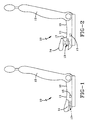
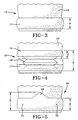
- the seat cushion restraint system deploys an airbag device 13 to elevate only the front part 14 of the seat cushion, shown in Figs. 1 and 3 in a condition in which the seat cushion restraint system has not been activated.
- the term "elevate” in its various forms is understood to mean lifting, boosting, raising, or inflating or otherwise moving something to a higher position with respect to the floor of a vehicle.
- Figs. 2 and 4 there is shown a diagrammatic side view and a diagrammatic fragmentary front view, respectively, of the vehicle seat 10 of Figs. 1 and 3 wherein the seat cushion restraint system 13 has been activated.
- the seat cushion restraint system disclosed herein comprises an apparatus incorporated into the structure of a vehicle seat that, as shown in Fig. 2 elevates only the front part 14 of the seat cushion 11 when a sensor (not shown) senses that a collision of selected severity has occurred.
- a sensor not shown
- the seat cushion restraint system lifts the lower legs of a vehicle occupant up from the floor to eliminate the possibility of bracing and to minimize interaction of the occupant's legs with the interior of the vehicle or an intruding structure.
- the seat cushion restraint system It is an important feature of the seat cushion restraint system that only the front part 14 of the seat cushion is elevated by the seat cushion restraint system while the remainder 16 of the seat cushion is not elevated because the seat cushion restraint system provides a restraint for the pelvis, eliminating the need for a full knee bolster.
- Computer simulations, which are described below in detail, have shown that the seat cushion restraint system of the present invention can dramatically reduce the axial loading in the tibias and femurs, and lumbar spine in a typical frontal crash situation, while retaining the same level of head and chest protection, when compared to a conventional vehicle occupant restraint system.
- a "conventional vehicle occupant restraint system” is understood to refer to a system comprising any full or partial combination of a lap belt, shoulder harness, knee bolster, and an airbag mounted in the steering wheel or dashboard.
- a seat cushion restraint system in accordance with the present invention comprises a means of sensing a crash of a selected severity and a means of elevating only the front part of the seat cushion a selected distance.
- the seat cushion restraint system comprises a crash sensor, a means for inflating an airbag, and an inflatable airbag disposed in the region of the front part of the seat cushion.
- the "front part of the seat cushion” is understood to mean a portion of the seat cushion which extends (a) across substantially the entire width of the seat cushion, and (b) from the front edge of the seat cushion towards the seatback for a distance of not more than about one-half of the distance between the front edge of the seat cushion and the seatback.
- the front part of the seat cushion is shown extending across the entire width of the seat cushion in the drawing figures, it is understood that the front part of the seat cushion may extend substantially across the entire width of the seat cushion while leaving lateral marginal portions of the seat cushion at either one or both edges thereof which are not elevated by the seat cushion restraint system so long as the seat cushion restraint system will still be capable of functioning to reduce occupant injuries in the manner described herein.
- the seat cushion extends from the front edge of the seat cushion towards the seatback for a distance of about 150 mm.
- the seat cushion restraint system of the present invention will function adequately if the front part of the seat cushion extends for a distance of about 100 to 200 mm from the front of the seat cushion towards the backrest. If a frontal collision is severe enough to induce injury to the lower extremities of a vehicle occupant, an airbag located in the region of the front part of the seat cushion is inflated to elevate only the front part of the seat cushion. The rising or inflating front part of the seat cushion will lift the vehicle occupant's feet away from the toeboard, thereby overcoming the occupant's natural reaction of bracing his, or her, feet against the toeboard or footboard of the vehicle, and minimizing leg interaction with any intruding or reactive structure. These two mechanisms will reduce or eliminate the potential for injury to the lower extremities and will also limit the forward motion of the pelvis during frontal crashes, thus acting as a substitute for a knee bolster.
- Elevating only the front part of the seat cushion requires a force that can easily be provided by inflating an airbag or by other suitable mechanical or pyrotechnical means.
- the timing requirement is similar to a frontal airbag, but with a longer fill time, since the device only has to overcome the inertia forces caused by the weight of the lower limbs.
- the raised front part of the seat cushion acts, in conjunction with the unraised remainder of the seat cushion, as a lower torso restraint in a fashion similar to a lap belt. It prevents the knees from penetrating deeply into the instrument panel, and thereby dramatically reduces the femur loads and the potential for knee and leg injury.
- frontal airbag is understood to refer to any airbag which is deployed from the steering wheel, dashboard, instrument panel, and so forth which inflates between an anterior surface of a vehicle occupant, who is facing the front of a vehicle, and the vehicle interior.
- frontal airbag trigger is understood to refer to the initiation of the process of inflating a frontal airbag when a sensor senses a crash significant enough to require deployment of a frontal airbag.
- the seat cushion restraint system employs at least one crash sensor (not shown) which may be a conventional sensor of any of the types which are well known in the crash sensing art, such as those taught in US 5,322,325 and US 5,306,883, which measure the rate of deceleration of the vehicle and produce an output signal or close and electrical circuit if the deceleration sensed indicates that a collision of a selected severity has occurred.
- the disclosures of US 5,322,325 and US 5,306,883 are referred to herein for the purpose of teaching crash sensors which may be employed in the practice of the present invention.
- the crash sensor(s) may be located in the front structure of the vehicle, in the steering wheel, in the dashboard, in the seat, or any other suitable location.
- the crash sensor(s) employed in the seat cushion restraint system may be dedicated only to the seat cushion restraint system or shared with other operating systems such as a belt pretensioning system or a system for deploying frontal airbags.
- the crash sensor acts by closing an electrical circuit or initiating a firing signal that initiates a series of events which result in an airbag being inflated by a means for inflation 15, commonly referred to in the art as an inflator.
- the crash sensor closes an electrical circuit or initiates a firing signal to the means for inflation 15 which activates a squib which ignites a pyrotechnic inflator employing sodium azide, or any other suitable gas generating compound, located in a housing. Combustion of the gas generating compound produces a gas which flows through any necessary filters and into the airbag.
- US 5,269,560 is referred to herein for the purpose of teaching a gas generating device as one means of inflation which may be adapted for use in the practice of the present invention.
- the crash sensor closes an electrical circuit or initiates a signal to the means for inflation 15 to open a valve or activate any other suitable means which allows compressed gas stored in a chamber which is part of the seat cushion restraint system to be rapidly introduced into the airbag to inflate it.
- US 5,433,476 is referred to herein for the purpose of teaching a stored gas inflator as one means of inflation which may be adapted for use in the practice of the present invention.
- a means for inflating 15 is a hybrid of the gas generating and stored gas inflators.
- US 5,290,060 is referred to herein for the purpose of teaching a hybrid stored gas/ gas generating inflator as one means of inflation which may be adapted for use in the practice of the present invention.
- the volume of gas generated or released is sufficient to inflate the airbag and raise only the front part of the seat cushion in the manner described herein.
- the pressure required for an airbag to lift the front part of the seat cushion in the seat cushion restraint system will of course vary from application to application, but should typically be in the range of about 150 to 200 kPa with a required airbag volume of less than about 10 liters.
- a seat cushion restraint system in accordance with a preferred embodiment of the present invention comprises a vehicle seat 10 having a seat cushion 11 and a backrest 12.
- An airbag system comprising an inflator 15 and an inflatable bag 13 is located in the region of the front part 14 of the seat cushion.
- a crash sensor (not shown) communicates with the inflator and activates the inflator when the crash sensor senses a crash of a selected severity. The activated inflator inflates the airbag thereby elevating only the front part of the seat cushion.
- a piece of fabric or plastic 17 may extend from the rear edge of the front part of the seat cushion 14 to the remainder 16 of the seat cushion.
- FIG. 5 there is shown a diagrammatic fragmentary view of a vehicle seat 20 in accordance with a second embodiment of the invention which relates specifically to a driver's seat and in which the seat cushion restraint system forces the driver's legs apart as it raises them to minimize the interaction between the driver's legs and the steering wheel.
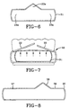
- Fig. 6 is a diagrammatic front cross-sectional view of an airbag 21 which may be employed with the embodiment of Fig. 5 and is embedded in or disposed below the seat cushion of a driver's seat.
- a central portion 23a of the airbag has a greater height than the lateral marginal portions 24a,25b of the airbag such that a portion 23 of the front part of the seat cushion is elevated to a height E which is greater than the height D to which the lateral marginal portions 24,25 of the front part of the seat cushion are elevated.
- the central portion 23a of the airbag is aligned with the steering wheel.
- the lateral sides of the central portion 23 of the front part of the seat cushion are sloped outwardly to force the legs of the occupant of the driver's seat apart sufficiently to reduce, or eliminate, the contact of his legs with the steering wheel.
- FIG. 7 there is shown a diagrammatic front cross-sectional view of a third embodiment of the invention which relates to a driver's seat 30.
- the airbag 31 When the airbag 31 is inflated it exerts a force in the direction indicated by the arrows causing hinged portions 32,33 of the front part of the seat cushion to swing upwardly and outwardly about pivot points located near the lateral edges of the seat cushion which forces the driver's legs apart as it raises them to minimize the interaction between the driver's legs and the steering wheel.
- the hinged portions 32,33 are normally adjacent to one another along a line which is aligned with the steering wheel when the seat cushion restraint system is not activated.
- FIG. 8 there is shown a diagrammatic cross-sectional view of an airbag 38, in an inflated condition, which may be employed in a fourth embodiment of the invention relating to a front bench seat for a vehicle.
- This embodiment functions similar to that described in regards to Figs. 5 and 6 except that the portion 36 of the airbag, and thus of the seat cushion, which is elevated to a greater extent than the lateral marginal portions 37,38 is offset to one side of the longitudinal axis of the vehicle sufficiently to be aligned with the steering wheel such that the lateral sides of the most elevated portion of the front part of the seat cushion are sloped outwardly to force the legs of the occupant of the driver's seat apart sufficiently to reduce, or eliminate, the contact of his legs with the steering wheel.
- the airbag has a first portion bordered by a pair of lateral marginal portions, the first portion of the airbag being closer to one side of the end of the seat than the other and having a greater height than the lateral marginal portions of the airbag such that a first portion 23 of the front part of the seat cushion is elevated to a height which is greater than the height of the rest 24,25 of the front part of the seat cushion.
- Fig. 9 there is shown a diagrammatic side view of a vehicle seat 40 in accordance with a fifth embodiment of the invention in which the seat cushion restraint system employs a spring loaded device 41 to elevate only the front part 42 of the seat cushion 43
- Fig. 10 is a diagrammatic side view of the vehicle seat of 40 Fig. 9 with the seat cushion restraint system activated.
- the means 41 of elevating only the front part of the seat cushion a selected distance is a spring loaded device in which the spring is normally in a compressed state as shown in Fig. 9, and is released to an expanded state when the compression of the spring is released as shown in Fig. 10.
- the compression on the spring is released in response to a signal from a crash sensor (not shown) when the crash sensor detects a crash of a selected severity.
- the spring may be a coil spring, as shown in Fig. 10, but could also be a leaf spring, or any other suitable form of stored energy which when compression thereon is released will exert a force upwardly to raise only the front part of the seat cushion a selected distance in accordance with the above stated mode of operation of a seat cushion restraint system.
- the compressive force on the spring, or other suitable form of stored energy may be released by mechanical, electrical, electromechanical, magnetic, pneumatic, hydraulic or any other suitable means.
- a piece of fabric or plastic 44 may extend from the rear edge of the front part of the seat cushion 42 to the remainder of the seat cushion.
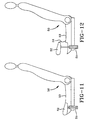
- Fig. 11 there is shown a diagrammatic side view of a vehicle seat 50 in accordance with a sixth embodiment of the invention in which the seat cushion restraint system employs a pyrotechnic device 51 to elevate only the front part 52 of the seat cushion 53
- Fig. 12 is a diagrammatic side view of the vehicle seat of Fig. 11 with the seat cushion restraint system activated.
- the means 51 of elevating only the front part of the seat cushion a selected distance is a pyrotechnic device in which a pyrotechnic compound is stored in a telescoping sleeve or in a cylinder having a piston slidably disposed therein.
- a piston type of device 51 is shown in Fig. 11.
- the force of the resulting explosion and any generated gas causes the piston to move upwardly thereby exerting a force upwardly to raise only the front part of the seat cushion a selected distance in accordance with the above stated mode of operation of a seat cushion restraint system.
- the igniter is activated by a signal or electrical impulse from a crash sensor (not shown) when the crash sensor detects a crash of a selected severity.
- the means of elevating only the front part of the seat cushion is preferably designed such when the piston, or telescoping sleeve extends upwardly as a result of the explosion, the piston or telescopic sleeve will remain locked in position with the front part of the seat cushion in its elevated position.
- a piece of fabric or plastic 54 may extend from the rear edge of the front part of the seat cushion 52 to the remainder of the seat cushion.
- Fig. 19 there is shown a diagrammatic side view of a vehicle seat 80 in accordance with a seventh embodiment of the invention which is very similar to the first embodiment shown in Figs. 1 and 2.
- the seat cushion restraint system employs an airbag 83 which is integral with the front part 84 of the seat cushion to elevate only the front part of the seat cushion when the airbag is inflated by a means for inflation 85.
- Pieces of fabric or plastic 83,87 extend from the front and rear edges, respectively, of the front part of the seat cushion 84 to the front of the seat cushion and the remainder of the seat cushion, respectively.
- FIG. 20 there is shown a diagrammatic side view of a vehicle seat 90 in accordance with an eighth embodiment of the invention in which the seat cushion restraint system employs an airbag 93 to elevate only the front part of the seat cushion upwardly around a pivot point located at the rear edge of the front part of the seat cushion when the airbag is inflated by a means for inflation 95.
- the seat cushion restraint system employs an airbag 93 to elevate only the front part of the seat cushion upwardly around a pivot point located at the rear edge of the front part of the seat cushion when the airbag is inflated by a means for inflation 95.
- MADYMO is a computer program which is available from TNO Road Vehicles Research Institute, Schoemakerstraat 97, Delft, The Netherlands.
- FMVSS Federal Motor Vehicle Safety Standard
- the baseline model used for comparison with the seat cushion restraint system, has a 150 liter airbag deployed from the dashboard and a knee bolster as passive restraints. Also considered is a configuration with an added three-point belt and pretensioner that is designed for use with a full size airbag.
- the restraints are optimized to a degree that all injury measures fall well within the FMVSS 208 limits.
- the dummy model used for this study is equipped with bracket joints in the femurs and tibias simulating load transducers. These allow registration of the axial forces and lateral bending moments, both of which play a role in injury causing mechanisms.
- Other features of the dummy model, which are of significance to this study, are a deformable abdomen and a compressible lumbar spine.
- the deformable abdomen is important for accurate modeling of the lap belt interaction.
- the compressible lumbar spine allows better assessment of loads and deformations directed through the lumbar spine.
- the primary restraint the airbag deployed from the dashboard, was modeled with approximately 3000 elements using the MADYMO Finite Element capability (Lupker et al., The MADYMO Finite Element Airbag Model, Proceedings of the Thirteenth International Technical Conference on Experimental Safety Vehicles, (91-S9-O-23), Paris, France. 1991).
- the bag is folded to fit inside a module mounted on the front of the dashboard.
- the configuration with belts uses a combination of finite element and spring-damper techniques to model the three-point belt restraint system.
- the seat model is extended with a simplified representation of this system.
- the seat cushion is split into two parts.
- the rear part of the seat cushion is 250 mm long and extends from the rear of the seat cushion.
- the front part of the seat cushion is 150 mm long and extends from the front of the seat cushion.
- the front part of the seat cushion is positioned underneath the vehicle occupant's femurs.
- the model allows lifting of only the front part of the seat cushion with rise height and timing as variables.
- the stiffness of the rear edge of the front part of the seat cushion was modified to reflect its use as a restraining device, but this does not influence the comfort characteristics of the cushion since the modification involves mainly the normally unexposed rear edge of the front part of the seat cushion.
- the stiffness of the knee bolster was reduced to the level of a typical trim panel because its function as a restraint for the lower torso is taken over by the seat cushion restraint system.
- the venting characteristic of the dashboard mounted airbag restraint system was slightly modified to reflect the increased penetration of the femurs into the airbag. No changes were made to the belt system.
- Two additional simulation models were used in the evaluation of the seat cushion restraint system. Both used the vehicle environment described above. However, in one model the initial position of the occupant was changed from a relaxed sitting position into a braced position. Joint locking and unlocking mechanisms were used to simulate yielding at higher force levels. In the second model, the fiftieth percentile occupant is replaced by a dummy model of a three year old child. The child dummy is placed on the tip of the seat, directly in-line with the seat cushion restraint system.
- Front seat cushion rise height was varied between 50 to 150 millimeters (mm), and time to maximum height was varied from 15 to 45 milliseconds (ms).
- the seat cushion restraint system was triggered at the same time as the dashboard mounted airbag, which was 15 ms after a sensor sensed that a severe collision had occurred.
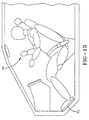
- Fig. 13 is a diagrammatic representation of a vehicle occupant 70 instinctively pushing forward with his feet against the toeboard 71 to restrain forward motion of his body.
- This protective bracing reaction may vary greatly from person to person, and may be greatly reduced if the collision is too sudden so that the vehicle occupant has no time to react.
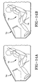
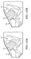
- Figs. 14A and B, 15A and B, and 16A and B are diagrammatic representations of the MADYMO simulation showing a comparison of the kinematics of an unbelted occupant 72 in the baseline vehicle 74 model versus an unbelted occupant 73 in a vehicle 75 equipped with the seat cushion restraint system.
- Figs. 14A and 14B show vehicle occupants 72,73 at the moment when a vehicle contacts another object head-on in a baseline vehicle 74 and a vehicle 75 equipped with a seat cushion restraint system 76 of the present invention, respectively.
- Figs. 14A and B, 15A and B, and 16A and B are diagrammatic representations of the MADYMO simulation showing a comparison of the kinematics of an unbelted occupant 72 in the baseline vehicle 74 model versus an unbelted occupant 73 in a vehicle 75 equipped with the seat cushion restraint system.
- Figs. 14A and 14B show vehicle occupants 72,73 at the moment when a vehicle contacts
- FIGS. 15A and 15B show vehicle occupants 72,73 at 60 ms after a vehicle contacts another object head-on in a baseline vehicle 74 and a vehicle 75 equipped with a seat cushion restraint system 76 of the present invention, respectively.
- Figs. 16A and 16B show vehicle occupants 72,73 at 80 ms after a vehicle contacts another object head-on in a baseline vehicle 74 and a vehicle 75 equipped with a seat cushion restraint system 76 of the present invention, respectively.
- These simulations show that the seat cushion restraint system succeeds in lifting the vehicle occupant's feet off the toeboard in a timely fashion. This prevents bracing of the vehicle occupant's legs that can cause high axial forces resulting in foot and ankle fractures.
- An apparatus according to the present invention prevents the vehicle occupant's feet from impacting the toeboard during the entire deceleration phase of the vehicle in the event of a collision.
- the elevated front part of the seat cushion provides a reaction surface for the pelvis of the vehicle occupant and acts as a lower torso restraint in a fashion similar to a lap belt. It prevents the knees from penetrating deeply into the instrument panel, and thereby dramatically reduces the femur loads and potential for knee and leg injury.
- the injury measures resulting from the baseline model all fell within the FMVSS 208 limits. However, with an axial force of 8,000 Newtons (8 kN) for the femurs and 5 kN for the tibias, the forces are in a range where lower limb fractures have been observed. The model does not indicate what kind of injuries might occur, but field data show that foot, ankle, and knee fractures are most common at these force levels.
- Fig. 17 is a graphic comparison of the injury measures of the baseline model and the model with the seat cushion restraint system, both without a seat belt being worn by the vehicle occupant.
- Fig. 17 shows the dramatic decrease of the axial forces in both femurs and tibias, while other injury measures remain at comparative levels.
- Table 1 presents a comparison of injury measures of the lower limbs for the baseline and seat cushion restraint system (SCRS) equipped models.
- SCRS seat cushion restraint system
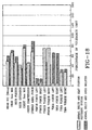
- Fig. 18 there is shown a graphic comparison of the injury measures of the baseline model and the model with the seat cushion restraint system, both with a seat belt being worn by the vehicle occupant.
- the axial force on the femurs is of course low, but the axial force on the tibias remains at approximately the same 5 kN level obtained in the unbelted baseline case.
- the seat cushion restraint system dramatically reduces these forces by lifting the vehicle occupant's feet off the toeboard before high bracing forces can occur.
- the reaction force of the lower torso against the seat cushion restraint system causes a reduction of the lap belt force of 25%. This reduces the risk of seat belt injuries in the abdominal region of the vehicle occupant.
- both with and without seat belt the axial force in the lumbar spine was reduced with the use of the seat cushion restraint system. On first encounter this seems contradictory to expectation.
- both the knee bolster and seat belt cause the lower torso to push deeper into the seat cushion. This causes the buttocks to bottom out against the anti-submarining seat pan, resulting in a significant upward force into the lumbar spine.
- the simulations show that a rise height of 100 mm is sufficient to lift the feet of a vehicle occupant off the floor and keep them away from tne toeboard during the entire deceleration phase of the vehicle. Although the lifting needs to be performed in a timely fashion, the simulations indicate that reaching the full lift height at 60 ms into the crash is sufficient to effectively restrain the lower torso.
- the relatively long (45 ms) rising time makes application of an airbag device to lift the seat cushion most favorable.
- the pressure required for such an airbag to lift the seat cushion restraint system is in the range of 150 to 200 kPa. With a required airbag volume of less than 10 liters, this falls well within the capability of airbag components currently in use.
- the optimized seat cushion restraint system rise height and time for the unbelted configuration also showed good results for the belted configuration without repositioning the lap belt anchor points.
- Restraint devices can only operate effectively if they are used as designed.
- the seat cushion restraint system works best if the occupant assumes a relaxed posture.
- typical human behavior prior to a crash is to brace for impact against the toeboard.
- Preliminary simulations with pre-bracing have shown the seat cushion restraint system to be quite effective in forcing the legs to bend at the knees.
- the injury measures for the lower extremities are increased over the relaxed case, the seat cushion restraint system still manages to significantly reduce the forces and moments compared to the configuration without seat cushion restraint system.
- a child dummy model (3-year old P3 dummy) study was also conducted.
- the simulation was configured for an unbelted, out-of-position child sitting on the tip of the seat.
- the simulation results showed no increase of injury measures due to the seat cushion restraint system being activated.
- Simulation study demonstrated the potential for significant reduction of lower limb injury measures through the use of the seat cushion restraint system disclosed herein. Simulations show a dramatic reduction of tibia and femur axial forces for unbelted occupants as well as an equally strong reduction of tibia axial forces and significant reduction of the lap belt forces for belted occupants. These reductions are achieved without affecting the injury measures for head and chest.
- the simulations indicate that raising the front 150 mm of the seat cushion by 100 mm, with a rise time of 45 ms (after airbag trigger), will suffice to keep the feet away from the toeboard during the deceleration phase of the vehicle, and to sufficiently retard the lower torso without needing a full knee bolster.
- Existing airbag technology can be applied to achieve this rise height in a timely fashion.
Landscapes
- Engineering & Computer Science (AREA)
- Aviation & Aerospace Engineering (AREA)
- Transportation (AREA)
- Mechanical Engineering (AREA)
- Air Bags (AREA)
Claims (12)
- Système de retenue d'un coussin de siège comprenant un siège de véhicule comportant un coussin de siège et un dossier, un moyen pour soulever uniquement la partie avant d'un coussin de siège, et un moyen de détection d'une collision du véhicule, le moyen de détection d'une collision communiquant avec le moyen de soulèvement de la seule partie avant du coussin de siège, et le moyen de soulèvement de la seule partie avant du coussin de siège étant actionné lorsque le moyen de détection d'une collision détecte une collision d'une gravité sélectionnée, caractérisé en ce que le siège du véhicule est le siège du conducteur du véhicule agencé derrière un volant, ledit moyen de soulèvement de la seule partie avant du coussin de siège comportant dans l'état gonflé une partie centrale délimitée par une paire de parties de bordure latérales, la partie centrale dudit moyen de soulèvement de la seule partie avant du coussin de siège ayant une hauteur supérieure à celle des parties de bordure latérales, de sorte que qu'une partie de la partie avant du coussin de siège est soulevée à une hauteur supérieure à celle du reste de la partie avant du coussin de siège, le coussin d'air en gonflant écartant ainsi les jambes du conducteur pour réduire l'interaction entre les jambes du conducteur et le volant.
- Système de retenue du coussin de siège selon la revendication 1, dans lequel le moyen destiné à soulever uniquement la partie avant du coussin de siège est un coussin d'air.
- Système de retenue du coussin de siège selon la revendication 1, dans lequel le moyen destiné à soulever uniquement la partie avant du coussin de siège est un dispositif actionné par ressort.
- Système de retenue du coussin de siège selon la revendication 1, dans lequel le moyen destiné à soulever uniquement la partie avant du coussin de siège est un dispositif à actionnement pyrotechnique.
- Système de retenue du coussin de siège selon la revendication 2, dans lequel le siège est un siège banquette avant d'un véhicule automobile agencé derrière un volant, le coussin d'air comportant à l'état gonflé une première partie alignée avec le volant et délimitée par une paire de parties de bordure latérales, la première partie du coussin d'air ayant à l'état gonflé une hauteur supérieure à celle des parties de bordure latérales du coussin d'air, de sorte qu'une première partie du coussin de siège et soulevée à une hauteur supérieure à celle de la partie restante de la partie avant du coussin de siège, le coussin d'air en gonflant écartant les jambes du conducteur pour réduire l'interaction entre les jambes du conducteur et le volant.
- Système de retenue du coussin de siège selon la revendication 2, dans lequel le coussin d'air est un coussin gonflable faisant partie d'un système de coussin d'air comprenant en outre un dispositif de gonflement, ledit coussin gonflable et le dispositif de gonflement étant agencés dans la région de la partie avant du coussin de siège, et un capteur de collision communiquant avec le dispositif de gonflement et actionnant le dispositif de gonflement lorsqu'un capteur de collision détecte une collision d'une gravité sélectionnée, le dispositif de gonflement actionné gonflant le coussin d'air et soulevant ainsi uniquement la partie avant du coussin de siège.
- Système de retenue du coussin de siège selon l'une quelconque des revendications précédentes, dans lequel la partie avant du coussin de siège s'étend sur une distance comprise entre environ 100 et 200 mm, de l'avant du coussin de siège vers le dossier.
- Système de retenue du coussin de siège selon l'une quelconque des revendications précédentes, dans lequel le coussin d'air soulève uniquement la partie avant du coussin de siège sur une distance d'au moins environ 100 mm lors de son actionnement.
- Système de retenue du coussin de siège selon la revendication 6, dans lequel le siège est un siège banquette avant d'un véhicule automobile agencé derrière un volant, le coussin d'air comportant à l'état gonflé une première partie alignée avec le volant et délimitée par une paire de parties de bordure latérales, la première partie du coussin d'air ayant dans l'état gonflé une hauteur supérieure à celle des parties de bordure latérales du coussin d'air, de sorte qu'une première partie du coussin de siège et soulevée à une hauteur supérieure à celle de la partie restante de la partie avant du coussin de siège, le coussin d'air en gonflant écartant les jambes du conducteur pour réduire l'interaction entre les jambes du conducteur et le volant.
- Système de retenue du coussin de siège selon la revendication 6, dans lequel le système de retenue du coussin de siège utilise un coussin d'air pour soulever uniquement la partie avant du coussin de siège autour d'un point de pivotement agencé au niveau du bord arrière de la partie avant du coussin de siège.
- Système de retenue du coussin de siège selon la revendication 6, dans lequel le coussin d'air fait partie intégrante de la partie avant du coussin de siège pour soulever uniquement la partie avant du coussin de siège lors du gonflement du coussin d'air par le dispositif de gonflement.
- Système de retenue du coussin de siège selon la revendication 6, dans lequel le siège est un siège avant d'un véhicule automobile agencé derrière un volant, la partie avant du coussin de siège comportant des parties articulées normalement adjacentes le long d'une ligne alignée avec le volant, le coussin d'air exerçant lors du gonflement une force entraínant le pivotement des parties articulées de la partie avant du coussin de siège vers le haut et vers l'extérieur autour de points de pivotement agencés près des bords latéraux du coussin de siège, écartant les jambes du conducteur en les soulevant pour réduire au minimum l'interaction entre les jambes du conducteur et le volant.
Applications Claiming Priority (3)
| Application Number | Priority Date | Filing Date | Title |
|---|---|---|---|
| US08/601,933 US5695242A (en) | 1996-02-15 | 1996-02-15 | Seat cushion restraint system |
| US601933 | 1996-02-15 | ||
| PCT/US1997/000751 WO1997029924A1 (fr) | 1996-02-15 | 1997-01-15 | Systeme de retenue de coussin de siege |
Publications (2)
| Publication Number | Publication Date |
|---|---|
| EP0879155A1 EP0879155A1 (fr) | 1998-11-25 |
| EP0879155B1 true EP0879155B1 (fr) | 2003-07-09 |
Family
ID=24409330
Family Applications (1)
| Application Number | Title | Priority Date | Filing Date |
|---|---|---|---|
| EP97902051A Expired - Lifetime EP0879155B1 (fr) | 1996-02-15 | 1997-01-15 | Système de retenue de coussin de siège |
Country Status (4)
| Country | Link |
|---|---|
| US (1) | US5695242A (fr) |
| EP (1) | EP0879155B1 (fr) |
| DE (1) | DE69723421T2 (fr) |
| WO (1) | WO1997029924A1 (fr) |
Cited By (2)
| Publication number | Priority date | Publication date | Assignee | Title |
|---|---|---|---|---|
| US11077817B1 (en) | 2020-01-23 | 2021-08-03 | Ford Global Technologies, Llc | Airbag assembly inflatable from seat bottom |
| US11091109B1 (en) | 2020-03-12 | 2021-08-17 | Ford Global Technologies, Llc | Knee bolster with variable resistance to forward force |
Families Citing this family (90)
| Publication number | Priority date | Publication date | Assignee | Title |
|---|---|---|---|---|
| US7243945B2 (en) * | 1992-05-05 | 2007-07-17 | Automotive Technologies International, Inc. | Weight measuring systems and methods for vehicles |
| US20070135982A1 (en) * | 1995-06-07 | 2007-06-14 | Automotive Technologies International, Inc. | Methods for Sensing Weight of an Occupying Item in a Vehicular Seat |
| US7779956B2 (en) * | 1995-06-07 | 2010-08-24 | Automotive Technologies International, Inc.. | Vehicular seats with weight sensing capability |
| US6425601B1 (en) | 1996-06-03 | 2002-07-30 | Universal Propulsion Company, Inc. | Air bag module |
| US5839756A (en) * | 1997-02-03 | 1998-11-24 | General Motors Corporation | Inflatable bladder |
| WO1999030931A2 (fr) * | 1997-12-18 | 1999-06-24 | Bs Rs Restraint Systems Gmbh | Coussin gonflable au sol, integre dans un tapis, sous forme d'element de retenue passif dans un vehicule |
| JP3715106B2 (ja) * | 1998-06-16 | 2005-11-09 | 日本発条株式会社 | 車両用シート装置 |
| US6142521A (en) * | 1998-07-15 | 2000-11-07 | Shephard; Mark E. | Vehicle crash protective system |
| DE29815521U1 (de) * | 1998-08-31 | 1998-12-03 | Thau, Barbara, 58285 Gevelsberg | Sitz für ein Fahrzeug |
| DE19841728B4 (de) * | 1998-09-12 | 2010-06-10 | Volkswagen Ag | Sicherheitseinrichtung mit einem Rückhaltesystem für einen Fahrzeugsitz |
| JP4080609B2 (ja) * | 1998-09-29 | 2008-04-23 | 日本発条株式会社 | 車両用座席 |
| DE19847603A1 (de) * | 1998-10-15 | 2000-04-20 | Volkswagen Ag | Vorrichtung zur Gewichtsensierung an einer Fahrzeugsitzanordnung |
| JP4120079B2 (ja) * | 1998-12-25 | 2008-07-16 | 日産自動車株式会社 | 自動車の衝撃緩和構造 |
| US6158766A (en) * | 1999-02-26 | 2000-12-12 | Lear Corporation | Vehicle floor system incorporating airbag |
| DE10011819B4 (de) | 1999-03-15 | 2005-05-12 | NHK Spring Co., Ltd., Yokohama | Fahrzeugsitzvorrichtung mit einer Einrichtung zum Verhindern des sogenannten Durchrutscheffekts |
| DE10011829C2 (de) * | 1999-03-15 | 2002-08-08 | Nhk Spring Co Ltd | Stellantrieb für ein Fahrzeuginsassenrückhaltesystem |
| US6604599B2 (en) * | 1999-03-15 | 2003-08-12 | Nhk Spring Co., Ltd. | Anti-submarine vehicle occupant restraint system |
| DE29922856U1 (de) | 1999-12-27 | 2000-05-04 | TRW Occupant Restraint Systems GmbH & Co. KG, 73553 Alfdorf | Fahrzeugsitz |
| JP2001247010A (ja) * | 1999-12-28 | 2001-09-11 | Takata Corp | 乗員保護装置 |
| FR2806051B1 (fr) * | 2000-03-10 | 2002-06-07 | Poudres & Explosifs Ste Nale | Ensemble de protection des membres inferieurs d'un occupant d'un vehicule automobile |
| US6296292B1 (en) * | 2000-05-18 | 2001-10-02 | Yakov Feldman | Vehicle crash-safety seat |
| EP1199214B1 (fr) | 2000-10-13 | 2006-06-21 | Nhk Spring Co.Ltd. | Système de retenu avec dispositif d'anti-sousmarinage pour passager de véhicule |
| US6836754B2 (en) * | 2001-01-31 | 2004-12-28 | Key Safety Systems, Inc. | Biomechanical system development of a restraint system |
| GB2374280B (en) * | 2001-03-09 | 2003-02-26 | Visteon Global Tech Inc | Seating system for a vehicle having a deceleration sensor |
| AU2002303420A1 (en) | 2001-04-24 | 2002-11-05 | Breed Automotive Technology, Inc. | Simplified modeling software interface and method |
| US6682141B2 (en) * | 2001-09-14 | 2004-01-27 | The Boeing Company | Seat assembly having a seat repositioning device and an associated method |
| JP2004009798A (ja) * | 2002-06-04 | 2004-01-15 | Takata Corp | 乗員保護装置 |
| JP3972736B2 (ja) * | 2002-06-04 | 2007-09-05 | タカタ株式会社 | 乗員保護装置 |
| JP3912195B2 (ja) * | 2002-06-12 | 2007-05-09 | タカタ株式会社 | 乗員保護装置 |
| KR100461101B1 (ko) * | 2002-06-15 | 2004-12-13 | 현대자동차주식회사 | 차량의 안티 서브마린 시트 |
| US7182191B2 (en) * | 2002-07-11 | 2007-02-27 | Autoliv Asp, Inc. | Motion damper |
| US20060027120A1 (en) * | 2002-07-11 | 2006-02-09 | Smith Bradley W | Assemblies including extendable, reactive charge-containing actuator devices |
| US7063019B2 (en) * | 2002-07-11 | 2006-06-20 | Autoliv Asp, Inc. | Assemblies including extendable, reactive charge-containing actuator devices |
| US6907817B2 (en) * | 2002-07-11 | 2005-06-21 | Autoliv Asp, Inc. | Linear actuator |
| WO2004011308A1 (fr) * | 2002-07-25 | 2004-02-05 | Autoliv Development Ab | Coussin gonflant pour dispositif de retenue d'occupant et procede de fabrication de coussin gonflant |
| US6764118B2 (en) | 2002-09-11 | 2004-07-20 | Autoliv Asp, Inc. | Active bumper assembly |
| GB0222720D0 (en) * | 2002-10-01 | 2002-11-06 | Dalphimetal Ltd | Vehicle seat with a pelvis energy management device |
| JP4135480B2 (ja) * | 2002-11-21 | 2008-08-20 | タカタ株式会社 | 乗員保護装置 |
| DE10301462B3 (de) * | 2003-01-16 | 2004-08-05 | Breed Automotive Technology, Inc., Lakeland | Kraftfahrzeug-Rückhaltevorrichtung |
| JP4269826B2 (ja) * | 2003-03-12 | 2009-05-27 | タカタ株式会社 | 乗員保護装置 |
| DE10320967A1 (de) * | 2003-05-09 | 2004-11-25 | Trw Occupant Restraint Systems Gmbh & Co. Kg | Aufblasbares Sitzrückhaltekissen |
| DE10328603B4 (de) * | 2003-06-25 | 2006-04-20 | Key Safety Systems, Inc., Sterling Heights | Airbagabdichtung |
| FR2857313B1 (fr) * | 2003-07-10 | 2006-11-24 | Pyroalliance | Dispositif d'amortissement du deplacement d'une piece impliquant un fil metallique |
| DE10340996B3 (de) * | 2003-09-05 | 2005-03-10 | Keiper Gmbh & Co Kg | Fahrzeugsitz mit Antisubmariningrampe |
| US20060017266A1 (en) * | 2003-09-30 | 2006-01-26 | Takata Corporation | Passenger protecting device |
| US20050067209A1 (en) * | 2003-09-30 | 2005-03-31 | Takata Corporation | Passenger protecting device |
| DE10351752A1 (de) * | 2003-11-06 | 2005-06-09 | Daimlerchrysler Ag | Sicherheitseinrichtung für ein Fahrzeug |
| US7380821B2 (en) * | 2004-01-27 | 2008-06-03 | Takata Corporation | Passenger protection apparatus |
| FR2866610B1 (fr) * | 2004-02-24 | 2007-05-18 | Renault Sas | Siege, notamment pour vehicule automobile |
| US7303040B2 (en) * | 2004-05-18 | 2007-12-04 | Autolive Asp, Inc. | Active vehicle hood system and method |
| US7354106B2 (en) * | 2004-07-22 | 2008-04-08 | Mjd Innovations, Llc | Impact-injury-minimizing seat structure and methodology |
| JP2006199271A (ja) * | 2004-12-24 | 2006-08-03 | Tkj Kk | 乗員拘束装置 |
| DE102005002464B4 (de) * | 2005-01-18 | 2009-04-02 | Autoliv Development Ab | Sicherheitsanordnung |
| US7441837B2 (en) * | 2005-04-25 | 2008-10-28 | Lear Corporation | Inflatable airbag system for vehicle seat assembly |
| JP4775111B2 (ja) * | 2005-05-25 | 2011-09-21 | タカタ株式会社 | 乗員保護装置 |
| WO2006132990A1 (fr) * | 2005-06-03 | 2006-12-14 | Abc Group, Inc. | Traversin actif |
| DE102006000887A1 (de) * | 2006-01-04 | 2007-07-05 | Autoliv Development Ab | Sicherheitseinrichtung |
| JP4850563B2 (ja) * | 2006-04-05 | 2012-01-11 | タカタ株式会社 | 車両シート、車両、エアバッグモジュール |
| US7758121B2 (en) * | 2006-04-17 | 2010-07-20 | Gm Global Technology Operations, Inc. | Active material based conformable and reconfigurable seats |
| US7648161B2 (en) * | 2006-04-19 | 2010-01-19 | Honda Motor Co., Ltd. | Airbag device |
| US7415903B2 (en) * | 2006-12-22 | 2008-08-26 | Chrysler Llc | Method and system for an impact sled footwell intrusion test |
| US8100471B2 (en) * | 2008-03-03 | 2012-01-24 | GM Global Technology Operations LLC | Adjustable seat ramp utilizing active material actuation |
| EP2163425A1 (fr) * | 2008-09-12 | 2010-03-17 | USSC Group, LLC | Ensemble de siège avec inclinaison du coussin |
| US7950688B2 (en) * | 2008-09-17 | 2011-05-31 | Tk Holdings Inc. | Airbag module |
| DE102009016606B4 (de) * | 2009-04-08 | 2014-08-28 | Autoliv Development Ab | Höhenverstellbarer Kraftfahrzeugsitz mit einem Seitengassack und Kraftfahrzeug mit einem solchen Fahrzeugsitz |
| US8407033B2 (en) * | 2009-06-23 | 2013-03-26 | Humanetics Innovative Solutions, Inc. | System for modeling dynamic response changes in an anthropomorphic dummy |
| DE102009047393A1 (de) * | 2009-12-02 | 2011-06-09 | Robert Bosch Gmbh | Haltevorrichtung zum Halten eines Fahrzeuginsassen in einem Fahrzeugsitz sowie Verfahren zum Betätigen der Haltevorrichtung |
| GB201112534D0 (en) * | 2011-07-21 | 2011-08-31 | Therrien Benoit Jr | Car seat riser for the lwoer part of the thighs |
| DE102011118344A1 (de) * | 2011-11-11 | 2013-05-23 | Volkswagen Aktiengesellschaft | Fahrzeugsitz, insbesondere Hintersitzanlage mit Sitzneigungsverstellung |
| US8523220B1 (en) | 2012-03-19 | 2013-09-03 | Amsafe, Inc. | Structure mounted airbag assemblies and associated systems and methods |
| US9199559B2 (en) * | 2012-04-20 | 2015-12-01 | Tk Holdings Inc. | Occupant protection device |
| DE102013101540B4 (de) * | 2013-02-15 | 2021-10-07 | Faurecia Autositze Gmbh | Fahrzeugsitz, insbesondere für ein Kraftfahrzeug |
| JP6089858B2 (ja) * | 2013-03-26 | 2017-03-08 | 豊田合成株式会社 | シートクッションエアバッグ装置 |
| US8955914B2 (en) | 2013-05-31 | 2015-02-17 | B/E Aerospace, Inc. | Leg restraint device for side-seated vehicle occupants |
| US9315271B2 (en) | 2013-05-31 | 2016-04-19 | B/E Aerospace, Inc. | Leg restraint device for side-facing seated vehicle occupants |
| US8894095B1 (en) * | 2013-05-31 | 2014-11-25 | B/E Aerospace, Inc. | Leg restraint device for side-facing seated vehicle occupants |
| US9944245B2 (en) | 2015-03-28 | 2018-04-17 | Amsafe, Inc. | Extending pass-through airbag occupant restraint systems, and associated systems and methods |
| US9527408B2 (en) * | 2015-03-31 | 2016-12-27 | Ford Global Technologies, Llc | Deployable thigh support in a vehicle seat |
| US9925950B2 (en) | 2015-04-11 | 2018-03-27 | Amsafe, Inc. | Active airbag vent system |
| US9744929B2 (en) * | 2015-11-25 | 2017-08-29 | Ford Global Technologies, Llc | Front passenger knee bolster deployment control |
| US9994138B2 (en) | 2015-12-02 | 2018-06-12 | Ford Global Technologies, Llc | Seat with deployable plastic beam |
| US10604259B2 (en) | 2016-01-20 | 2020-03-31 | Amsafe, Inc. | Occupant restraint systems having extending restraints, and associated systems and methods |
| US10899456B2 (en) | 2017-10-06 | 2021-01-26 | Rockwell Collins, Inc. | Dynamically tilted seat pan |
| US10940776B2 (en) | 2019-04-17 | 2021-03-09 | Ford Global Technologies, Llc | Adjustable seat |
| US11091070B2 (en) | 2019-05-16 | 2021-08-17 | Ford Global Technologies, Llc | Suspension system for vehicle seat |
| US11820267B2 (en) | 2019-06-11 | 2023-11-21 | Ford Global Technologies, Llc | Vehicle seat |
| JP7272332B2 (ja) * | 2020-08-11 | 2023-05-12 | 豊田合成株式会社 | 乗員保護装置 |
| US11247629B1 (en) * | 2020-08-17 | 2022-02-15 | Ford Global Technologies, Llc | Vehicle airbag |
| US12545157B2 (en) | 2023-11-17 | 2026-02-10 | Ford Global Technologies, Llc | Lifter for vehicle seat bottom |
| US12419427B1 (en) | 2024-06-17 | 2025-09-23 | Erick Stephen Grimm | Portable headrest and sleeping apparatus |
Family Cites Families (32)
| Publication number | Priority date | Publication date | Assignee | Title |
|---|---|---|---|---|
| US2735476A (en) * | 1956-02-21 | fieber | ||
| US2834606A (en) * | 1955-10-05 | 1958-05-13 | Harry A Bertrand | Safety device for passengers |
| US2943866A (en) * | 1957-01-10 | 1960-07-05 | Witter Mathias | Protective device |
| US3452834A (en) * | 1966-11-21 | 1969-07-01 | George R Gaut | Automotive safety device |
| US3591232A (en) * | 1969-04-01 | 1971-07-06 | Lewis B Simon | Automatic vehicle occupant restraint |
| US3642303A (en) * | 1970-02-13 | 1972-02-15 | Gen Motors Corp | Vehicle occupant restraint system |
| US3618978A (en) * | 1970-05-11 | 1971-11-09 | Gen Motors Corp | Inflatable restraint for vehicle occupant |
| US3702706A (en) * | 1971-01-15 | 1972-11-14 | Ford Motor Co | Motor vehicle restraint device |
| FR2237452A5 (en) * | 1973-07-12 | 1975-02-07 | Rayne Andre | Crash protection system for car passengers - spring actuated seat part lifts thighs to keep passenger in seat |
| US3981520A (en) * | 1975-05-05 | 1976-09-21 | Liberty Mutual Insurance Company | Protective enclosure for passengers of transport devices |
| US3998291A (en) * | 1975-08-06 | 1976-12-21 | Edwin George Davis | Automotive safety seat |
| US4154472A (en) * | 1977-09-09 | 1979-05-15 | Gateway Industries, Inc. | Method and apparatus for protecting a vehicle occupant |
| JPS54155523A (en) * | 1978-05-26 | 1979-12-07 | Takada Kogyo Kk | Seat for car |
| JPS5853525A (ja) * | 1981-09-25 | 1983-03-30 | Mazda Motor Corp | 自動車のシ−ト |
| JPS60240535A (ja) * | 1984-05-15 | 1985-11-29 | Daihatsu Motor Co Ltd | 着座者の保護装置 |
| GB2218385A (en) * | 1988-03-29 | 1989-11-15 | Trw Repa Gmbh | Vehicle passive restraint system with gas bag and knee cushion |
| JPH01275230A (ja) * | 1988-04-27 | 1989-11-02 | Honda Motor Co Ltd | 車輌用シート |
| US5290060A (en) * | 1992-12-14 | 1994-03-01 | Morton International, Inc. | Hybrid gas generator for air bag inflatable restraint systems |
| US5322325A (en) * | 1989-10-19 | 1994-06-21 | Breed Automotive Technology, Inc. | Safing velocity change sensor |
| JPH03227745A (ja) * | 1989-12-25 | 1991-10-08 | Mazda Motor Corp | 乗員の姿勢制御装置 |
| DE4032385C2 (de) * | 1990-10-12 | 1994-06-23 | Audi Ag | Sicherheitseinrichtung für einen Fahrzeuginsassen |
| US5269560A (en) * | 1990-12-18 | 1993-12-14 | Twr Inc. | Initiator assembly for air bag inflator |
| EP0523192B1 (fr) * | 1991-02-01 | 1996-05-22 | ITT Automotive Europe GmbH | Systeme pivotant de retenue des passagers pour vehicules a moteur |
| JP3082392B2 (ja) * | 1992-02-05 | 2000-08-28 | タカタ株式会社 | 車両乗員の保護装置 |
| SE470096B (sv) * | 1992-04-10 | 1993-11-08 | Volvo Ab | Luftkuddesystem för sidokollisioner |
| US5306883A (en) * | 1993-03-24 | 1994-04-26 | Trw Technar Inc. | Deceleration sensor switch for use in a vehicle occupant safety system |
| US5567006A (en) * | 1993-10-01 | 1996-10-22 | Mccarthy; Joseph | Vehicle seat with articulated sections |
| US5425551A (en) * | 1993-12-17 | 1995-06-20 | General Motors Corporation | Cushion fold for a supplemental inflatable restraint system |
| US5458366A (en) * | 1994-06-01 | 1995-10-17 | Morton International, Inc. | Compartmentalized airbag knee bolster |
| US5433476A (en) * | 1994-07-27 | 1995-07-18 | Breed Automotive Technology, Inc. | Temperature compensated stored gas inflator |
| US5558399A (en) * | 1994-09-13 | 1996-09-24 | Serber; Hector | Seat and lumbar motion chair, assembly and method |
| US5556160A (en) * | 1994-10-04 | 1996-09-17 | Mikami; Tatuya | Seat with user protecting means |
-
1996
- 1996-02-15 US US08/601,933 patent/US5695242A/en not_active Expired - Lifetime
-
1997
- 1997-01-15 EP EP97902051A patent/EP0879155B1/fr not_active Expired - Lifetime
- 1997-01-15 WO PCT/US1997/000751 patent/WO1997029924A1/fr not_active Ceased
- 1997-01-15 DE DE69723421T patent/DE69723421T2/de not_active Expired - Lifetime
Cited By (2)
| Publication number | Priority date | Publication date | Assignee | Title |
|---|---|---|---|---|
| US11077817B1 (en) | 2020-01-23 | 2021-08-03 | Ford Global Technologies, Llc | Airbag assembly inflatable from seat bottom |
| US11091109B1 (en) | 2020-03-12 | 2021-08-17 | Ford Global Technologies, Llc | Knee bolster with variable resistance to forward force |
Also Published As
| Publication number | Publication date |
|---|---|
| DE69723421T2 (de) | 2004-06-09 |
| WO1997029924A1 (fr) | 1997-08-21 |
| EP0879155A1 (fr) | 1998-11-25 |
| US5695242A (en) | 1997-12-09 |
| DE69723421D1 (de) | 2003-08-14 |
Similar Documents
| Publication | Publication Date | Title |
|---|---|---|
| EP0879155B1 (fr) | Système de retenue de coussin de siège | |
| EP1240049B1 (fr) | Siege de vehicule | |
| US4154472A (en) | Method and apparatus for protecting a vehicle occupant | |
| US7669897B2 (en) | Vehicle passenger restraining apparatus and method for the same | |
| GB2347851A (en) | Anti-submarining seat. | |
| EP4041602B1 (fr) | Ensembles coussin gonflable de sécurité pour une position d'assise de véhicule équipée d'un composant utilitaire | |
| JPH03281455A (ja) | 車体側部への衝突エネルギ吸収装置 | |
| US6520541B1 (en) | Vehicle safety seat system | |
| JP3480231B2 (ja) | エアバッグ装置 | |
| JP2001239872A (ja) | 乗員保護装置 | |
| EP0915782B1 (fr) | Dispositif de securite | |
| JPH11192915A (ja) | 自動車用安全設備 | |
| JP3307245B2 (ja) | 乗員の姿勢制御装置 | |
| GB2408027A (en) | A safety arrangement in a vehicle foot well | |
| WO2007063914A1 (fr) | Dispositif de protection pour occupant | |
| EP2394869B1 (fr) | Agencement de sécurité pour passagers de véhicule automibile | |
| WO2022097509A1 (fr) | Dispositif de siège à coussin de sécurité gonflable intégré | |
| Elias et al. | Large school bus safety restraint evaluation-phase II | |
| WO2000036951A1 (fr) | Systeme de siege de securite pour vehicule | |
| Helleman et al. | Seat and Airbag Design to Mitigate Frontal Crash Lower Limb Injuries | |
| WO2025004672A1 (fr) | Dispositif de protection d'occupant | |
| KR20260033597A (ko) | 승차인 보호 장치 | |
| KR0133263B1 (ko) | 충돌시 운전자 보호용 시트장치 | |
| KR19980022279U (ko) | 충격 완화용 시트 | |
| Rudd et al. | Evaluation of lower limb injury mitigation from inflatable carpet in sled tests with intrusion using the THOR Lx |
Legal Events
| Date | Code | Title | Description |
|---|---|---|---|
| PUAI | Public reference made under article 153(3) epc to a published international application that has entered the european phase |
Free format text: ORIGINAL CODE: 0009012 |
|
| 17P | Request for examination filed |
Effective date: 19980908 |
|
| AK | Designated contracting states |
Kind code of ref document: A1 Designated state(s): DE FR GB IT |
|
| RAP1 | Party data changed (applicant data changed or rights of an application transferred) |
Owner name: BREED AUTOMOTIVE TECHNOLOGY, INC. |
|
| 17Q | First examination report despatched |
Effective date: 20020417 |
|
| GRAH | Despatch of communication of intention to grant a patent |
Free format text: ORIGINAL CODE: EPIDOS IGRA |
|
| RTI1 | Title (correction) |
Free format text: SEAT CUSHION RESTRAINT SYSTEM |
|
| RTI1 | Title (correction) |
Free format text: SEAT CUSHION RESTRAINT SYSTEM |
|
| RTI1 | Title (correction) |
Free format text: SEAT CUSHION RESTRAINT SYSTEM |
|
| GRAH | Despatch of communication of intention to grant a patent |
Free format text: ORIGINAL CODE: EPIDOS IGRA |
|
| GRAA | (expected) grant |
Free format text: ORIGINAL CODE: 0009210 |
|
| AK | Designated contracting states |
Designated state(s): DE FR GB IT |
|
| REG | Reference to a national code |
Ref country code: GB Ref legal event code: FG4D |
|
| REF | Corresponds to: |
Ref document number: 69723421 Country of ref document: DE Date of ref document: 20030814 Kind code of ref document: P |
|
| PGFP | Annual fee paid to national office [announced via postgrant information from national office to epo] |
Ref country code: GB Payment date: 20031211 Year of fee payment: 8 |
|
| PGFP | Annual fee paid to national office [announced via postgrant information from national office to epo] |
Ref country code: FR Payment date: 20040102 Year of fee payment: 8 |
|
| ET | Fr: translation filed | ||
| PLBE | No opposition filed within time limit |
Free format text: ORIGINAL CODE: 0009261 |
|
| STAA | Information on the status of an ep patent application or granted ep patent |
Free format text: STATUS: NO OPPOSITION FILED WITHIN TIME LIMIT |
|
| 26N | No opposition filed |
Effective date: 20040414 |
|
| PG25 | Lapsed in a contracting state [announced via postgrant information from national office to epo] |
Ref country code: IT Free format text: LAPSE BECAUSE OF NON-PAYMENT OF DUE FEES Effective date: 20050115 Ref country code: GB Free format text: LAPSE BECAUSE OF NON-PAYMENT OF DUE FEES Effective date: 20050115 |
|
| GBPC | Gb: european patent ceased through non-payment of renewal fee |
Effective date: 20050115 |
|
| PG25 | Lapsed in a contracting state [announced via postgrant information from national office to epo] |
Ref country code: FR Free format text: LAPSE BECAUSE OF NON-PAYMENT OF DUE FEES Effective date: 20050930 |
|
| REG | Reference to a national code |
Ref country code: FR Ref legal event code: ST |
|
| PGFP | Annual fee paid to national office [announced via postgrant information from national office to epo] |
Ref country code: DE Payment date: 20160127 Year of fee payment: 20 |
|
| REG | Reference to a national code |
Ref country code: DE Ref legal event code: R071 Ref document number: 69723421 Country of ref document: DE |