EP0879169B1 - Vehicule aquatique - Google Patents
Vehicule aquatique Download PDFInfo
- Publication number
- EP0879169B1 EP0879169B1 EP97904528A EP97904528A EP0879169B1 EP 0879169 B1 EP0879169 B1 EP 0879169B1 EP 97904528 A EP97904528 A EP 97904528A EP 97904528 A EP97904528 A EP 97904528A EP 0879169 B1 EP0879169 B1 EP 0879169B1
- Authority
- EP
- European Patent Office
- Prior art keywords
- water
- foil
- vehicle
- foils
- support structure
- Prior art date
- Legal status (The legal status is an assumption and is not a legal conclusion. Google has not performed a legal analysis and makes no representation as to the accuracy of the status listed.)
- Expired - Lifetime
Links
Images

Classifications
-
- B—PERFORMING OPERATIONS; TRANSPORTING
- B63—SHIPS OR OTHER WATERBORNE VESSELS; RELATED EQUIPMENT
- B63B—SHIPS OR OTHER WATERBORNE VESSELS; EQUIPMENT FOR SHIPPING
- B63B1/00—Hydrodynamic or hydrostatic features of hulls or of hydrofoils
- B63B1/16—Hydrodynamic or hydrostatic features of hulls or of hydrofoils deriving additional lift from hydrodynamic forces
- B63B1/24—Hydrodynamic or hydrostatic features of hulls or of hydrofoils deriving additional lift from hydrodynamic forces of hydrofoil type
- B63B1/28—Hydrodynamic or hydrostatic features of hulls or of hydrofoils deriving additional lift from hydrodynamic forces of hydrofoil type with movable hydrofoils
-
- B—PERFORMING OPERATIONS; TRANSPORTING
- B63—SHIPS OR OTHER WATERBORNE VESSELS; RELATED EQUIPMENT
- B63B—SHIPS OR OTHER WATERBORNE VESSELS; EQUIPMENT FOR SHIPPING
- B63B1/00—Hydrodynamic or hydrostatic features of hulls or of hydrofoils
- B63B1/16—Hydrodynamic or hydrostatic features of hulls or of hydrofoils deriving additional lift from hydrodynamic forces
- B63B1/24—Hydrodynamic or hydrostatic features of hulls or of hydrofoils deriving additional lift from hydrodynamic forces of hydrofoil type
- B63B1/26—Hydrodynamic or hydrostatic features of hulls or of hydrofoils deriving additional lift from hydrodynamic forces of hydrofoil type having more than one hydrofoil
-
- B—PERFORMING OPERATIONS; TRANSPORTING
- B63—SHIPS OR OTHER WATERBORNE VESSELS; RELATED EQUIPMENT
- B63H—MARINE PROPULSION OR STEERING
- B63H1/00—Propulsive elements directly acting on water
- B63H1/30—Propulsive elements directly acting on water of non-rotary type
- B63H1/36—Propulsive elements directly acting on water of non-rotary type swinging sideways, e.g. fishtail type
-
- B—PERFORMING OPERATIONS; TRANSPORTING
- B63—SHIPS OR OTHER WATERBORNE VESSELS; RELATED EQUIPMENT
- B63H—MARINE PROPULSION OR STEERING
- B63H16/00—Marine propulsion by muscle power
- B63H16/08—Other apparatus for converting muscle power into propulsive effort
-
- B—PERFORMING OPERATIONS; TRANSPORTING
- B63—SHIPS OR OTHER WATERBORNE VESSELS; RELATED EQUIPMENT
- B63H—MARINE PROPULSION OR STEERING
- B63H16/00—Marine propulsion by muscle power
- B63H2016/005—Marine propulsion by muscle power used on vessels dynamically supported, or lifted out of the water by hydrofoils
Definitions
- This invention relates to a water vehicle.
- GB-A-441916 discloses a water vehicle having foils arranged on opposing sides of the body of the vehicle. These are used as ailerons for steering the vehicle and do not contribute to the propelling force of the vehicle. The vessel is propelled by a motor.
- a water vehicle which includes first and second foils which are at least partly submersible in water and which are movable in the water, at least to a limited extent, relatively to each other, to generate a force for propelling the vehicle through the water.
- the said relative foil movement may cause, or be due to, at least one of the following: at least limited rotational movement of the first foil about an axis which is transverse to a longitudinal axis of the first foil; a variation in the inclination of the first foil about an axis which may extend generally in a direction which is parallel to the longitudinal direction of the first foil.
- the water vehicle may include water skimmer means and connection means which is mounted for pivotal movement about an axis and which connects the skimmer means to the first foil.
- the water vehicle may include a third foil which is at least partly submersible and which is connected by means of the connecting means to the skimmer means.
- the water vehicle may include a support structure and means securing the foils to the support structure, the said relative foil movement being due to or caused by at least one of the following: relative movement between at least two sections or components of the support structure; relative movement between the support structure and the securing means; relative movement between at least one foil and the support structure; relative movement between at least one foil and the securing means.
- the water vehicle may include biasing means which, at least to a limited extent, dampens the said relative foil movement.
- the biasing means may take on any suitable form and may, for example, include a resiliently deflectable or deformable member, a spring, a shock absorber mechanism, or the like.
- the force which is exerted by the biasing means may be adjustable in order to vary the characteristics of the water vehicle.
- a water vehicle which includes a support structure, at least first and second foils which are at least partly submersible in water and which are secured to the support structure, steering means for controlling the direction of movement of the vehicle and means which permits limited movement of the first foil, while submerged in the water, relatively to at least part of the support structure to generate a force for propelling the vehicle through the water.
- the steering means may comprise rudder means of any suitable type, or means for causing at least limited rotational or pivotal movement of the first foil relatively to the second foil.
- the aforementioned support structure which may be in the form of a frame, may include a platform or the like in order to provide support for a user.
- the user may stand n the platform which may include feet engaging formations such as straps or the like.
- the frame may be made from any suitable material such as aluminium, a composite material such as fibre reinforced resin or the like, or be moulded from suitable material such as pressure moulded plastics material.
- the foils may be similarly formed and, according to a preferred aspect of the invention, the foils are formed from extruded or pultruded sections of a suitable material, e.g. aluminium, or are pressure moulded from a suitable plastics material.
- a suitable material e.g. aluminium
- the invention also provides a method of propelling a water vehicle which includes the steps of at least partially submerging at least first and second foils of the vehicle in a body of water, and repeatedly varying the inclination of each foil while submerged in the body of water, in order to generate a force for propelling the vehicle through water.
- the surface of the body of water may be contacted by skimmer means which may be used to control the depth to which the first foil is submerged in the body of water.
- the method may include the additional step of repeatedly varying the inclination of a third foil, which is at least partly submerged in the body of water.
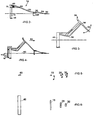
- FIG. 1 of the accompanying drawings illustrates a water vehicle 10 which includes a support structure or frame 12 and a canard arrangement 14.
- the canard 14 is shown from the side in Figure 2. It includes a support 16 to which is attached a transversely extending longitudinal leading foil 18, a lever 20 which is secured at a pivot point 22 to the support 16, an arm 24 which is attached at a pivot point 26 to the lever 20, a transversely extending V-shaped foil 28 which is secured to the arm 24, and a skimmer plate 30 at a forward end of the arm 24.
- a spring 31, optionally of variable stiffness, can be used to dampen movement between the support 16 and the lever 20.
- the support structure or frame 12 is shown from the side in Figure 3. It includes a tubular frame assembly 32, a forwardly extending steering rod 34 which is mounted for rotation in a sleeve 36 of the frame assembly 32 and which is movable by means of a handlebar 38, a platform 40 on the frame assembly, two downwardly extending support members 42 and 44 respectively, and a transversely extending longitudinal trailing foil 46 which is secured to the support members 42 and 44.
- the support structure and the foils may be made from any suitable material.
- Use may for example be made of light weight composite materials such as carbon fibre, fibre glass or the like, or of light weight metals such as aluminium. It is also possible to form the various components by means of injection moulding processes.
- the steering rod 34 is attached to the lever 20 of the canard arrangement at a pivot point 48. Referring to Figure 2 it can be seen that this point is slightly in front of an upright portion of the support 16.
- the platform 40 is adapted to support a user and, for this purpose, locating straps 50 may be provided on the platform to receive the feet of the user.
- the user is able to grip the handlebar 38.
- the steering rod 34 can be rotated so that, viewed in plan the leading foil 18 and the V-shaped foil 28, together with the skimmer 30, are rotatable, or pivotable, relatively to the trailing foil 46. This type of movement is shown, somewhat schematically, in Figure 6.
- the foils 46, 18 and 28 are, in use, submerged in a body of water, not shown.
- the water line is indicated by the numeral 50.
- the skimmer 30 essentially rides on the surface of the water.
- the force on the canard 14 is applied in front of the foil 18. This causes a slight, yet stable, variation in the inclination of the foils 18 and 28.
- the foremost foil 28 is V-shaped to ensure that its wake does not interact with the downwardly extending support 16.
- the user is able to vary the force exerted by the user's legs on the platform relatively to the force which is exerted by the user through the user's arms on the handlebar 38. In this way the user can simultaneously generate thrust on the foil 46 and on the foil 18, with the amount of thrust, in each case, depending on requirement and ability.
- the relative movement between the various foils is made possible, in this instance, by the pivot connections at the points 22 and 48.
- This relative movement can be damped, as has been indicated, by making use of springs, rubber bushes or any equivalent mechanism, located at a suitable position between the foils.
- Steering of the vehicle is effected, as has been explained, by rotating the steering rod 34 about its longitudinal axis.
- FIG 7 shows a canard arrangement 60 according to a variation of the invention.
- This arrangement includes a lever 62, a downwardly depending support 64 to which is attached a longitudinally extending foil 66, and a skimmer plate 68 at a forward end of the lever.
- This arrangement is substantially the same as the leading portion of the canard arrangement shown in Figure 2.
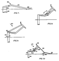
- Figure 10 illustrates the arrangement 60 secured to a steering rod 34 of a support frame 70, which, in many respects, is similar to the support frame 12 shown in Figure 1. Similar numerals have been employed in Figure 10 to indicate similar components.
- the support structure has a platform 40, downwardly depending support members 42 and 44, and a trailing foil 46.
- the support structure which is also shown in Figure 8, includes two sections designated 70A and 70B respectively. These are connected to one another at a pivot point 72.
- the section 70A supports the platform 40 while the section 70B has the steering arrangement attached to it.
- a small degree of pivotal movement of one section can take place relatively to the other section.
- a compression spring 74 interconnects the two sections.
- the stiffness of the spring can be adjusted by compressing the spring to a greater or lesser extent using a suitable screw mechanism.
- thrust is generated primarily by the trailing foil 46 while the leading foil 66 acts as a stabilizer but, on the other hand, gives rise to drag.
- the arrangement shown in Figure 10 is therefore less efficient than the arrangement shown in Figure 1 in which both foils are used to generate thrust.
- the skimmer plate 68 imparts further stability to the arrangement and ensures that the foil 66 does not sink too deep into the water as forward movement of the vehicle takes place.
- the structure 70 could be made relatively rigid and the steering rod 34 could be resilient or flexible to some extent. Again, with bobbing movement of the user on the platform 40, different amounts of force are exerted on the two foils and relative movement between the foils takes place as the rod 34 flexes. This permits the inclination of the foils to be varied and, in accordance with the principles which have been outlined hereinbefore, at least the rear foil 46 generates thrust which maintains the forward speed of the vehicle and which in turn ensures that lift is generated which prevents the vehicle from sinking into the water.
- FIG 9 shows support structure 80 according to a variation of the invention. Again like reference numerals have been employed to designate like components. In this case a degree of relative movement between the trailing foil 46 and the support structure is permitted by mounting the support members 42 and 44 to the support structure at hinge or pivot points 82. These points could include torsion mounts such as rubber axles or, alternatively, the degree of relative movement could be constrained by making use of biasing members similar to what is shown in Figures 8 and 10.
- the entire support structure may be formed from a suitable flexible material.
- the degree to which the foils can move relatively to one another is important and this is determined by trial and experiment and by experience of the user.
- the skimmer plate As the vehicle traverses through the water body in which it is operated the skimmer plate impinges on the water surface. This helps substantially in maintaining stability for it assists in keeping the leading foil more or less at the desired depth in the water. If the leading foil sinks too low then a greater reactive force is exerted by the water surface on the skimmer which tends to correct the situation. On the other hand if the leading foil tends to rise from the water then a restoring force is automatically exerted by gravity action which effectively rotates a leading end of the vehicle closer towards the water body.
- the foils may be made in any appropriate way and, in one example of the invention, the foils are made from extruded sections for example of aluminium or a plastics material.
- the foils may have constant cross-sections or be formed with tapers.
- the foils are preferably hollow and are sealed at opposed ends by means of suitable plugs.
- a rudder to steer the vehicle, instead of, or if required, in addition to, pivoting one foil relatively to the other.
- a hand or foot-controlled rudder 80 could be fixed at any suitable location to the support structure of the vehicle. By controlling the orientation of the rudder the vehicle can be steered.
Landscapes
- Ocean & Marine Engineering (AREA)
- Physics & Mathematics (AREA)
- Chemical & Material Sciences (AREA)
- Engineering & Computer Science (AREA)
- Combustion & Propulsion (AREA)
- Mechanical Engineering (AREA)
- Fluid Mechanics (AREA)
- Automatic Cycles, And Cycles In General (AREA)
- Mechanical Treatment Of Semiconductor (AREA)
- Motorcycle And Bicycle Frame (AREA)
- Toys (AREA)
- Exhaust Silencers (AREA)
- Actuator (AREA)
- Transmission Devices (AREA)
- Medicines Containing Material From Animals Or Micro-Organisms (AREA)
Claims (11)
- Véhicule aquatique englobant des premier et deuxième profilés (18, 46) au moins partiellement submersibles dans l'eau et pouvant se déplacer l'un par rapport à l'autre dans l'eau, du moins jusqu'à une certaine limite, pour produire une force de propulsion du véhicule à travers l'eau.
- Véhicule aquatique selon la revendication 1, englobant un moyen de patinage sur l'eau (30) et un moyen de connexion (20) monté de sorte à pivoter autour d'un axe (22) et connectant le moyen de patinage au premier profilé.
- Véhicule aquatique selon la revendication 2, englobant un troisième profilé (28), au moins partiellement submersible et connecté par l'intermédiaire du moyen de connexion au moyen de patinage.
- Véhicule aquatique selon l'une quelconque des revendications 1 à 3, englobant une structure de support (12) et un moyen pour fixer les profilés à la structure de support, ledit déplacement relatif des profilés étant dû ou entraíné par au moins un des déplacements suivants: le déplacement relatif entre au moins deux sections ou composants de la structure de support; le déplacement relatif entre la structure de support et le moyen de fixation; le déplacement relatif entre au moins un profilé et la structure de support; le déplacement relatif entre au moins un profilé et le moyen de fixation.
- Véhicule aquatique selon l'une quelconque des revendications 1 à 4, englobant un moyen de direction (34) pour assurer la commande de la direction du déplacement du véhicule.
- Véhicule aquatique selon l'une quelconque des revendications précédentes, dans lequel les profilés constituent le seul support du véhicule lors de la propulsion du véhicule à travers l'eau.
- Véhicule aquatique englobant une structure de support (12), au moins des premier et deuxième profilés (18, 46), au moins partiellement submersibles dans l'eau et fixés à la structure de support, un moyen de direction (34) pour assurer la commande de la direction du déplacement du véhicule, et un moyen (22, 72) permettant un déplacement limité du premier profilé, pendant sa submersion dans l'eau, par rapport à au moins une partie de la structure de support pour produire une force de propulsion du véhicule à travers l'eau.
- Véhicule aquatique selon la revendication 7, englobant un troisième profilé (28) au moins en partie submersible et pouvant se déplacer au moins par rapport au premier profilé ou au deuxième profilé.
- Procédé de propulsion d'un véhicule aquatique englobant les étapes de submersion au moins partielle des premier et deuxième profilés (18, 46) du véhicule dans un corps d'eau et de variation répétée de l'inclinaison de chaque profilé pendant sa submersion dans le corps d'eau pour produire une force de propulsion du véhicule à travers l'eau.
- Procédé selon la revendication 9, dans lequel l'inclinaison du premier profilé (18) par rapport au deuxième profilé (46) est variée.
- Procédé selon les revendications 9 ou 10, englobant les étapes de mise en contact de la surface du corps d'eau avec un moyen de patinage (30) et d'utilisation du moyen de patinage pour assurer au moins en partie la commande de la profondeur de submersion du premier profilé (18) dans le corps d'eau.
Applications Claiming Priority (3)
| Application Number | Priority Date | Filing Date | Title |
|---|---|---|---|
| ZA9601095 | 1996-02-12 | ||
| ZA961095 | 1996-02-12 | ||
| PCT/GB1997/000382 WO1997029010A1 (fr) | 1996-02-12 | 1997-02-12 | Vehicule aquatique |
Publications (2)
| Publication Number | Publication Date |
|---|---|
| EP0879169A1 EP0879169A1 (fr) | 1998-11-25 |
| EP0879169B1 true EP0879169B1 (fr) | 2000-08-23 |
Family
ID=25585536
Family Applications (1)
| Application Number | Title | Priority Date | Filing Date |
|---|---|---|---|
| EP97904528A Expired - Lifetime EP0879169B1 (fr) | 1996-02-12 | 1997-02-12 | Vehicule aquatique |
Country Status (9)
| Country | Link |
|---|---|
| US (1) | US6099369A (fr) |
| EP (1) | EP0879169B1 (fr) |
| AT (1) | ATE195692T1 (fr) |
| AU (1) | AU711387B2 (fr) |
| CA (1) | CA2245902C (fr) |
| DE (1) | DE69702891T2 (fr) |
| ES (1) | ES2152651T3 (fr) |
| TW (1) | TW330901B (fr) |
| WO (1) | WO1997029010A1 (fr) |
Families Citing this family (15)
| Publication number | Priority date | Publication date | Assignee | Title |
|---|---|---|---|---|
| US6178905B1 (en) * | 1998-08-19 | 2001-01-30 | Waveblade Corporation | Personal hydrofoil water craft |
| US7021232B2 (en) * | 2003-09-07 | 2006-04-04 | Shane Chen | Self propelled hydrofoil device |
| US7819074B2 (en) * | 2003-09-07 | 2010-10-26 | Shane Chen | Self-propelled hydrofoil device with flexible steering assembly |
| WO2008008011A1 (fr) * | 2006-07-10 | 2008-01-17 | Madiana Ab | Dispositif de transport sur l'eau |
| US7662004B1 (en) | 2006-11-14 | 2010-02-16 | March Philip A | Human-powered flapping hydrofoil craft |
| US8801478B2 (en) * | 2009-10-08 | 2014-08-12 | Fishboat, Inc. | Watercraft |
| BRPI1002941B1 (pt) * | 2010-08-20 | 2020-12-22 | Mateus Frois Santa Catarina | barco que se converte em aparelho de ginástica |
| CN102602523A (zh) * | 2011-01-24 | 2012-07-25 | 陈和 | 人力驱动的水上划艇 |
| US9180949B2 (en) * | 2013-09-25 | 2015-11-10 | Paul Hansen | Human-powered watercraft |
| WO2015093984A1 (fr) * | 2013-12-19 | 2015-06-25 | Howard-Willis Guy | Dispositif de sports nautiques et sa méthode d'utilisation |
| CN104192260A (zh) * | 2014-09-09 | 2014-12-10 | 华东理工大学 | 拉动式水翼装置 |
| GB2533564A (en) | 2014-12-18 | 2016-06-29 | Caccia Alex | A watercraft |
| AU2017402770A1 (en) | 2017-03-06 | 2019-10-17 | Bright Spark Innovations Gp Limited | Human powered hydrofoil vehicle and use method |
| US11511831B1 (en) | 2018-10-22 | 2022-11-29 | Drew Allen Krah | Human powered watercraft |
| US12263912B2 (en) * | 2021-03-05 | 2025-04-01 | Bi-Thermal Aspen Earth, L.L.C. | Composite hydrofoil components and systems |
Family Cites Families (8)
| Publication number | Priority date | Publication date | Assignee | Title |
|---|---|---|---|---|
| GB441916A (en) * | 1934-05-12 | 1936-01-29 | Wsevolode Grunberg | Method and apparatus for nautical locomotion with dynamic sustentation |
| GB1134011A (en) * | 1964-09-09 | 1968-11-20 | Peter Thomas Mence Nott | Improvements in hydroplanes |
| US3606859A (en) * | 1968-07-10 | 1971-09-21 | Michael D Skitsko | Aquatic vehicle |
| US4100876A (en) * | 1977-05-18 | 1978-07-18 | The Boeing Company | Hydrofoil fixed strut steering control |
| GB2117712A (en) * | 1981-12-05 | 1983-10-19 | Michael John Spavins | Buoyant craft with hydrovane |
| FR2563800A1 (fr) * | 1984-05-07 | 1985-11-08 | Rusev Simeon | Objet muni d'ailes de portance hydrodynamique |
| FR2697794B1 (fr) * | 1992-11-10 | 1995-01-20 | Gilles Durand | Hydravion - Voilier destiné à voler au ras des flots, propulsé par la force du vent. |
| WO1995015882A1 (fr) * | 1993-12-06 | 1995-06-15 | Rodolphe Proverbio | Embarcation a propulsion musculaire |
-
1997
- 1997-02-12 CA CA002245902A patent/CA2245902C/fr not_active Expired - Fee Related
- 1997-02-12 AT AT97904528T patent/ATE195692T1/de not_active IP Right Cessation
- 1997-02-12 ES ES97904528T patent/ES2152651T3/es not_active Expired - Lifetime
- 1997-02-12 EP EP97904528A patent/EP0879169B1/fr not_active Expired - Lifetime
- 1997-02-12 AU AU17303/97A patent/AU711387B2/en not_active Ceased
- 1997-02-12 US US09/125,045 patent/US6099369A/en not_active Expired - Fee Related
- 1997-02-12 DE DE69702891T patent/DE69702891T2/de not_active Expired - Fee Related
- 1997-02-12 WO PCT/GB1997/000382 patent/WO1997029010A1/fr not_active Ceased
- 1997-03-12 TW TW086103046A patent/TW330901B/zh active
Also Published As
| Publication number | Publication date |
|---|---|
| US6099369A (en) | 2000-08-08 |
| AU711387B2 (en) | 1999-10-14 |
| AU1730397A (en) | 1997-08-28 |
| CA2245902C (fr) | 2006-11-21 |
| DE69702891T2 (de) | 2001-04-05 |
| TW330901B (en) | 1998-05-01 |
| ATE195692T1 (de) | 2000-09-15 |
| WO1997029010A1 (fr) | 1997-08-14 |
| EP0879169A1 (fr) | 1998-11-25 |
| CA2245902A1 (fr) | 1997-08-14 |
| ES2152651T3 (es) | 2001-02-01 |
| DE69702891D1 (de) | 2000-09-28 |
Similar Documents
| Publication | Publication Date | Title |
|---|---|---|
| EP0879169B1 (fr) | Vehicule aquatique | |
| AU2014345540B2 (en) | Tilting mechanism for a multi-wheeled tilting vehicle | |
| US6428022B1 (en) | Inline skateboard | |
| US5309861A (en) | Shock-absorber mounted seat for personal watercraft and boats | |
| CA2593339C (fr) | Vehicule tout-terrain chenille | |
| US4681333A (en) | Wind propelled land vehicle | |
| EP1897799B1 (fr) | Dispositif de stabilisation dynamique d'un engin sous-marin | |
| US20130001909A1 (en) | Scooters and scooter steering systems | |
| US20080305698A1 (en) | Towed personal watercraft | |
| US7500679B2 (en) | Board for supporting front of snow vehicle | |
| US11173942B2 (en) | Steering control system for snow vehicles | |
| US4014283A (en) | Watercraft, particularly for watersports | |
| US7819074B2 (en) | Self-propelled hydrofoil device with flexible steering assembly | |
| US6199649B1 (en) | Snowmobile steering and ski suspension | |
| CA2511458C (fr) | Ensemble roue d'apprentissage flexible | |
| CN1918030A (zh) | 滑雪运动的滑行装置 | |
| US4398741A (en) | Anti-nose-dive apparatus of a motorcycle | |
| US6854743B2 (en) | Articulated steering sled | |
| US7694986B2 (en) | Vehicles having stabilization and stabilizers for vehicles | |
| US5816871A (en) | Muscle-powered watercraft | |
| CA2289369A1 (fr) | Systeme de direction et de suspension de motoneige | |
| CA1123879A (fr) | Motoneige a chassis articule | |
| FR2744981A1 (fr) | Dispositif d'amortisseur pour le calage d'un aileron hydrodynamique porteur et engin nautique muni d'un tel dispositif:la planche-hydroptere a voile | |
| CA2562813C (fr) | Planche de support de l'avant d'un vehicule de neige | |
| AU2001100507A4 (en) | Ride-on toy and drive assembly therefor |
Legal Events
| Date | Code | Title | Description |
|---|---|---|---|
| PUAI | Public reference made under article 153(3) epc to a published international application that has entered the european phase |
Free format text: ORIGINAL CODE: 0009012 |
|
| 17P | Request for examination filed |
Effective date: 19980826 |
|
| AK | Designated contracting states |
Kind code of ref document: A1 Designated state(s): AT DE ES FR GB GR IT PT |
|
| 17Q | First examination report despatched |
Effective date: 19981126 |
|
| GRAG | Despatch of communication of intention to grant |
Free format text: ORIGINAL CODE: EPIDOS AGRA |
|
| RAP1 | Party data changed (applicant data changed or rights of an application transferred) |
Owner name: PUZEY, MICHAEL ROYDON |
|
| GRAG | Despatch of communication of intention to grant |
Free format text: ORIGINAL CODE: EPIDOS AGRA |
|
| GRAH | Despatch of communication of intention to grant a patent |
Free format text: ORIGINAL CODE: EPIDOS IGRA |
|
| GRAH | Despatch of communication of intention to grant a patent |
Free format text: ORIGINAL CODE: EPIDOS IGRA |
|
| GRAA | (expected) grant |
Free format text: ORIGINAL CODE: 0009210 |
|
| RIN1 | Information on inventor provided before grant (corrected) |
Inventor name: PUZEY, MICHAEL ROYDON |
|
| AK | Designated contracting states |
Kind code of ref document: B1 Designated state(s): AT DE ES FR GB GR IT PT |
|
| PG25 | Lapsed in a contracting state [announced via postgrant information from national office to epo] |
Ref country code: IT Free format text: LAPSE BECAUSE OF FAILURE TO SUBMIT A TRANSLATION OF THE DESCRIPTION OR TO PAY THE FEE WITHIN THE PRESCRIBED TIME-LIMIT;WARNING: LAPSES OF ITALIAN PATENTS WITH EFFECTIVE DATE BEFORE 2007 MAY HAVE OCCURRED AT ANY TIME BEFORE 2007. THE CORRECT EFFECTIVE DATE MAY BE DIFFERENT FROM THE ONE RECORDED. Effective date: 20000823 Ref country code: FR Free format text: LAPSE BECAUSE OF FAILURE TO SUBMIT A TRANSLATION OF THE DESCRIPTION OR TO PAY THE FEE WITHIN THE PRESCRIBED TIME-LIMIT Effective date: 20000823 Ref country code: AT Free format text: LAPSE BECAUSE OF FAILURE TO SUBMIT A TRANSLATION OF THE DESCRIPTION OR TO PAY THE FEE WITHIN THE PRESCRIBED TIME-LIMIT Effective date: 20000823 |
|
| REF | Corresponds to: |
Ref document number: 195692 Country of ref document: AT Date of ref document: 20000915 Kind code of ref document: T |
|
| REF | Corresponds to: |
Ref document number: 69702891 Country of ref document: DE Date of ref document: 20000928 |
|
| PG25 | Lapsed in a contracting state [announced via postgrant information from national office to epo] |
Ref country code: PT Free format text: LAPSE BECAUSE OF FAILURE TO SUBMIT A TRANSLATION OF THE DESCRIPTION OR TO PAY THE FEE WITHIN THE PRESCRIBED TIME-LIMIT Effective date: 20001123 |
|
| PG25 | Lapsed in a contracting state [announced via postgrant information from national office to epo] |
Ref country code: GR Free format text: LAPSE BECAUSE OF FAILURE TO SUBMIT A TRANSLATION OF THE DESCRIPTION OR TO PAY THE FEE WITHIN THE PRESCRIBED TIME-LIMIT Effective date: 20001124 |
|
| EN | Fr: translation not filed | ||
| REG | Reference to a national code |
Ref country code: ES Ref legal event code: FG2A Ref document number: 2152651 Country of ref document: ES Kind code of ref document: T3 |
|
| PLBE | No opposition filed within time limit |
Free format text: ORIGINAL CODE: 0009261 |
|
| STAA | Information on the status of an ep patent application or granted ep patent |
Free format text: STATUS: NO OPPOSITION FILED WITHIN TIME LIMIT |
|
| 26N | No opposition filed | ||
| REG | Reference to a national code |
Ref country code: GB Ref legal event code: IF02 |
|
| PGFP | Annual fee paid to national office [announced via postgrant information from national office to epo] |
Ref country code: GB Payment date: 20070212 Year of fee payment: 11 |
|
| PGFP | Annual fee paid to national office [announced via postgrant information from national office to epo] |
Ref country code: ES Payment date: 20070213 Year of fee payment: 11 |
|
| PGFP | Annual fee paid to national office [announced via postgrant information from national office to epo] |
Ref country code: DE Payment date: 20070323 Year of fee payment: 11 |
|
| GBPC | Gb: european patent ceased through non-payment of renewal fee |
Effective date: 20080212 |
|
| PG25 | Lapsed in a contracting state [announced via postgrant information from national office to epo] |
Ref country code: DE Free format text: LAPSE BECAUSE OF NON-PAYMENT OF DUE FEES Effective date: 20080902 |
|
| REG | Reference to a national code |
Ref country code: ES Ref legal event code: FD2A Effective date: 20080213 |
|
| PG25 | Lapsed in a contracting state [announced via postgrant information from national office to epo] |
Ref country code: GB Free format text: LAPSE BECAUSE OF NON-PAYMENT OF DUE FEES Effective date: 20080212 |
|
| PG25 | Lapsed in a contracting state [announced via postgrant information from national office to epo] |
Ref country code: ES Free format text: LAPSE BECAUSE OF NON-PAYMENT OF DUE FEES Effective date: 20080213 |