EP0879197B1 - Maschine zum einkerben - Google Patents
Maschine zum einkerben Download PDFInfo
- Publication number
- EP0879197B1 EP0879197B1 EP96928615A EP96928615A EP0879197B1 EP 0879197 B1 EP0879197 B1 EP 0879197B1 EP 96928615 A EP96928615 A EP 96928615A EP 96928615 A EP96928615 A EP 96928615A EP 0879197 B1 EP0879197 B1 EP 0879197B1
- Authority
- EP
- European Patent Office
- Prior art keywords
- creasing
- strip
- matrix
- platen
- article
- Prior art date
- Legal status (The legal status is an assumption and is not a legal conclusion. Google has not performed a legal analysis and makes no representation as to the accuracy of the status listed.)
- Expired - Lifetime
Links
- 239000011159 matrix material Substances 0.000 claims abstract description 31
- 230000000694 effects Effects 0.000 description 2
Images
Classifications
-
- B—PERFORMING OPERATIONS; TRANSPORTING
- B31—MAKING ARTICLES OF PAPER, CARDBOARD OR MATERIAL WORKED IN A MANNER ANALOGOUS TO PAPER; WORKING PAPER, CARDBOARD OR MATERIAL WORKED IN A MANNER ANALOGOUS TO PAPER
- B31F—MECHANICAL WORKING OR DEFORMATION OF PAPER, CARDBOARD OR MATERIAL WORKED IN A MANNER ANALOGOUS TO PAPER
- B31F1/00—Mechanical deformation without removing material, e.g. in combination with laminating
- B31F1/08—Creasing
-
- B—PERFORMING OPERATIONS; TRANSPORTING
- B26—HAND CUTTING TOOLS; CUTTING; SEVERING
- B26F—PERFORATING; PUNCHING; CUTTING-OUT; STAMPING-OUT; SEVERING BY MEANS OTHER THAN CUTTING
- B26F1/00—Perforating; Punching; Cutting-out; Stamping-out; Apparatus therefor
- B26F1/38—Cutting-out; Stamping-out
- B26F1/44—Cutters therefor; Dies therefor
-
- B—PERFORMING OPERATIONS; TRANSPORTING
- B26—HAND CUTTING TOOLS; CUTTING; SEVERING
- B26F—PERFORATING; PUNCHING; CUTTING-OUT; STAMPING-OUT; SEVERING BY MEANS OTHER THAN CUTTING
- B26F1/00—Perforating; Punching; Cutting-out; Stamping-out; Apparatus therefor
- B26F1/38—Cutting-out; Stamping-out
- B26F1/40—Cutting-out; Stamping-out using a press, e.g. of the ram type
-
- B—PERFORMING OPERATIONS; TRANSPORTING
- B26—HAND CUTTING TOOLS; CUTTING; SEVERING
- B26F—PERFORATING; PUNCHING; CUTTING-OUT; STAMPING-OUT; SEVERING BY MEANS OTHER THAN CUTTING
- B26F1/00—Perforating; Punching; Cutting-out; Stamping-out; Apparatus therefor
- B26F1/38—Cutting-out; Stamping-out
- B26F1/44—Cutters therefor; Dies therefor
- B26F2001/4445—Matrices, female dies, creasing tools
Definitions
- the present invention relates to creasing machines. Such machines are commonly employed to pre-form crease lines in cardboard or corrugated cardboard, but the present invention is not limited to such applications.
- Known creasing machines comprise platens which carry creasing matrices formed of matrix elements which project from the platen surface and have small gaps therebetween. Above each such gap is a creasing rule of the platen which is movable in a direction substantially perpendicular to the surface. In its raised position, the creasing rule stands clear of the creasing matrix whilst in its lower position the creasing rule projects into the area between the matrix elements.
- the creasing rule is moved to its raised position, and a sheet moved substantially parallel to the platen until the desired crease line lies between the respective gap and the creasing rule.
- the creasing rule is then moved sharply into its lowered position, and then to its raised position. A crease is thus produced in the sheet.
- An object of the present invention is to overcome this problem.
- the present invention provides in one aspect a creasing machine for imparting a crease to a creasable article, the machine comprising a platen, a creasing matrix secured to the surface of the platen and upstanding therefrom, and a creasing rule moveable transversely between a position spaced from the creasing matrix and a position adjacent or within the creasing matrix; and a strip positioned ahead of the creasing matrix and in the path of the article to be creased, the strip having a profile whose leading edge is curvilinear and whose undersurface lies flush with the surface of the platen at all times, the profiled strip acting to deflect an incoming article thereby preventing or minimising contact between the article with an upstanding face of the creasing matrix.
- the profiled strip may be adhered to the platen surface by, for example, double-sided tape.
- the tape is adhered to the strip undersurface over only a recessed rear portion of the strip undersurface, the leading portion of the profiled stipe lying flush with the platen surface.
- the profiled strip operates inter alia to create a vortex in the boundary layer around the moving article which creates lift in those cases where the incoming article is liable to strike the creasing matrix. Should contact occur between an incoming article and the profiled strip, the profile of the strip prevents damage occurring to the article thereby preventing jamming of the machine.
- the present invention is capable of working in both a contactless fashion and one in which damage or jamming does not occur should there be contact between the article and the profiled strip.
- a preferred profile is an aerodynamic profile having a thickness for the aerodynamic profile is between one and two times the height of the creasing matrix.
- the exact positioning of the strip is not essential so long as the functional requirement is met.
- a suitable spacing between the creasing matrix and the strip is between one and two times the gap of an element of the creasing matrix.
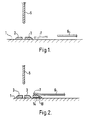
- the known creasing machine illustrated in Figure 1 has a platen 1 which carries a creasing matrix formed of matrix elements 2, 3 which project from the platen 1 and have a small gap 4 therebetween. Above the gap is a creasing rule 5 which is moveable in a direction substantially perpendicular to the surface of the platen 1. In its raised position, the creasing rule stands clear of the creasing matrix whilst in its lower position the creasing rule projects into the gap 4 between the matrix elements 2, 3.
- the creasing rule 5 is moved to its raised position, and the sheet 6 is moved substantially parallel to the platen 1 until the desired crease line lies between the gap 4 and the creasing rule 5.
- the creasing rule 5 is then moved sharply into its lowered position, and then to its raised position. A crease is thus produced in the sheet 6.
- Figure 2 shows a creasing machine similar to that of Figure 1, but with the addition of a profiled lead strip 10. Similar integers to those shown in Figure 1 have been given the same reference numerals.
- the lead strip is of an aerodynamic profile and has a curvilinear leading edge 11 and a thicker end 12 positioned closer to the creasing matrix.
- the lead strip 10 is, in this embodiment, positioned ahead of the creasing matrix by a distance roughly equal to the width of the creasing element 3. Its height is roughly twice that of the creasing element 3.
- the aerodynamic profile is similar to that of a common aircraft wing.
- the profiled strip 10 has double-sided tape 14 secured to its undersurface which is recessed to receive the tape to ensure that the leading edge of the strip always lies flush with the surface of the platen and does not lift in use of the machine.
- the tape extends from the trailing edge of the strip to a position just inboard from the strip leading edge.
- One effect of the lead strip 10 is to affect the air within the boundary layer of the sheet 6. Such air will normally be carried along with the sheet 6 so that it moves. It therefore has a translational velocity component relative to the lead strip 10. As the leading edge 7 of the sheet 6 passes over the lead strip 10, a vortex is created behind the lead strip 10 which raises the leading edge 7 to prevent it striking the matrix element 3. In the event that contact is made, the effect on the sheet leading edge is marginal because of the profile of the strip 10.
Landscapes
- Engineering & Computer Science (AREA)
- Mechanical Engineering (AREA)
- Life Sciences & Earth Sciences (AREA)
- Forests & Forestry (AREA)
- Making Paper Articles (AREA)
- Manufacturing And Processing Devices For Dough (AREA)
- Folding Of Thin Sheet-Like Materials, Special Discharging Devices, And Others (AREA)
- Machines For Manufacturing Corrugated Board In Mechanical Paper-Making Processes (AREA)
- Iron Core Of Rotating Electric Machines (AREA)
- Pharmaceuticals Containing Other Organic And Inorganic Compounds (AREA)
- Eye Examination Apparatus (AREA)
- Nonmetallic Welding Materials (AREA)
- Compressor (AREA)
Claims (3)
- Kerbmaschine zum Einprägen einer Kerbe in einem korbbaren Gegenstand mit einer Platte (1), mit einer auf der Oberfläche der Platte festgelegten und von dieser vorstehenden Kerbmatrix (2, 3) und mit einem Kerblineal (5), welches quer beweglich ist zwischen einer Stellung, in der es von der Kerbmatrix (2, 3) im Abstand liegt und einer Stellung, in der es benachbart zur Kerbmatrix oder in dieser befindlich ist, wobei die Maschine dadurch gekennzeichnet ist, daß sie eine Leiste (10) aufweist, die vor der Kerbmatrix und im Bewegungspfad des einzukerbenden Gegenstandes (6) angeordnet ist, daß die Leiste (10) ein Profil besitzt, dessen Vorderrand gekrümmt ist und dessen Unterseite mit der Oberfläche der Platte (1) immer fluchtet, und daß die Profilleiste eine Auslenkung eines ankommenden Gegenstandes bewirkt und dadurch eine Berührung zwischen dem Gegenstand mit einer vorstehenden Fläche der Kerbmatrix verhindert oder vermindert.
- Kerbmaschine nach Anspruch 1, bei welcher die Profilleiste (10) auf der Platte mit einem doppelseitigen Klebeband (14) festgelegt ist.
- Kerbmaschine nach Anspruch 2, bei welcher die Unterseite der Profilleiste (10) eine Ausnehmung aufweist, um das doppelseitige Klebeband (14) aufzunehmen, wobei sich diese Ausnehmung vom Hinterrand der Leiste (10) nach einer Stelle erstreckt, die im Inneren der Leiste im Abstand zu ihrem Vorderrand liegt.
Applications Claiming Priority (3)
| Application Number | Priority Date | Filing Date | Title |
|---|---|---|---|
| GBGB9601827.0A GB9601827D0 (en) | 1996-01-30 | 1996-01-30 | Creasing machine |
| GB9601827 | 1996-01-30 | ||
| PCT/GB1996/002131 WO1997028074A1 (en) | 1996-01-30 | 1996-08-27 | Creasing machines |
Publications (2)
| Publication Number | Publication Date |
|---|---|
| EP0879197A1 EP0879197A1 (de) | 1998-11-25 |
| EP0879197B1 true EP0879197B1 (de) | 2000-03-15 |
Family
ID=10787792
Family Applications (1)
| Application Number | Title | Priority Date | Filing Date |
|---|---|---|---|
| EP96928615A Expired - Lifetime EP0879197B1 (de) | 1996-01-30 | 1996-08-27 | Maschine zum einkerben |
Country Status (6)
| Country | Link |
|---|---|
| EP (1) | EP0879197B1 (de) |
| AT (1) | ATE190585T1 (de) |
| AU (1) | AU6833496A (de) |
| DE (1) | DE69607215D1 (de) |
| GB (1) | GB9601827D0 (de) |
| WO (1) | WO1997028074A1 (de) |
Cited By (1)
| Publication number | Priority date | Publication date | Assignee | Title |
|---|---|---|---|---|
| US10618240B2 (en) | 2014-11-05 | 2020-04-14 | Bobst Mex Sa | Method for production of a female embossing tool, a female embossing tool, and an embossing module equipped therewith |
Families Citing this family (2)
| Publication number | Priority date | Publication date | Assignee | Title |
|---|---|---|---|---|
| BE1016747A3 (nl) * | 2005-09-27 | 2007-05-08 | Rillivo Bv Met Beperkte Aanspr | Verbeterde stansrilplaat. |
| JP2016041460A (ja) * | 2014-08-19 | 2016-03-31 | 大創株式会社 | ジャンピングシール |
Family Cites Families (6)
| Publication number | Priority date | Publication date | Assignee | Title |
|---|---|---|---|---|
| US3884132A (en) * | 1974-01-11 | 1975-05-20 | Channel Creasing Matrix Inc | Magnetically located scoring die matrix |
| FR2602158B1 (fr) * | 1986-07-30 | 1989-08-18 | Bombled Ind | Cisaille-guillotine a commande numerique equipee d'un dispositif d'alimentation |
| US5163894A (en) * | 1991-05-30 | 1992-11-17 | Masaaki Ogawa | Female die for paperboard stamper |
| DE9114037U1 (de) * | 1991-08-22 | 1992-01-16 | Vossen, Franz, 7768 Stockach | Vorrichtung und Hilfsmittel zum Behandeln von Zurichtebogen für Bandstahlschnitte |
| DE9214654U1 (de) * | 1992-10-28 | 1994-03-03 | PCE Paper Converting Equipment GmbH, 93073 Neutraubling | Matrizenbogen für ein Stanzwerkzeug zum Herstellen von Kartonagenzuschnitten |
| DE9411502U1 (de) * | 1994-07-20 | 1994-10-27 | Schäfer, Michael, 90542 Eckental | Zurichtstreifen |
-
1996
- 1996-01-30 GB GBGB9601827.0A patent/GB9601827D0/en active Pending
- 1996-08-27 AT AT96928615T patent/ATE190585T1/de active
- 1996-08-27 DE DE69607215T patent/DE69607215D1/de not_active Expired - Lifetime
- 1996-08-27 WO PCT/GB1996/002131 patent/WO1997028074A1/en not_active Ceased
- 1996-08-27 AU AU68334/96A patent/AU6833496A/en not_active Abandoned
- 1996-08-27 EP EP96928615A patent/EP0879197B1/de not_active Expired - Lifetime
Cited By (2)
| Publication number | Priority date | Publication date | Assignee | Title |
|---|---|---|---|---|
| US10618240B2 (en) | 2014-11-05 | 2020-04-14 | Bobst Mex Sa | Method for production of a female embossing tool, a female embossing tool, and an embossing module equipped therewith |
| US11203174B2 (en) | 2014-11-05 | 2021-12-21 | Bobst Mex Sa | Method for production of a female embossing tool, a female embossing tool, and an embossing module equipped therewith |
Also Published As
| Publication number | Publication date |
|---|---|
| GB9601827D0 (en) | 1996-04-03 |
| AU6833496A (en) | 1997-08-22 |
| DE69607215D1 (de) | 2000-04-20 |
| ATE190585T1 (de) | 2000-04-15 |
| EP0879197A1 (de) | 1998-11-25 |
| WO1997028074A1 (en) | 1997-08-07 |
Similar Documents
| Publication | Publication Date | Title |
|---|---|---|
| US20070227323A1 (en) | Trimming device for trimming a lateral edge | |
| EP0879197B1 (de) | Maschine zum einkerben | |
| EP2210844B1 (de) | Verfahren und Vorrichtung für die Zufuhr und Faltung von Blättern | |
| US2952457A (en) | System for separating and conveying flat articles | |
| US4715925A (en) | Apparatus for forming connection bridges between stacks of corrugated cardboard sheets in a corrugator | |
| CA2226826C (en) | Device for turning the front panel of a plate-like workpiece within a folder-gluer | |
| CA1045170A (en) | Overlapped sheet-feeding method and machine | |
| CN211053886U (zh) | 一种印刷纸板的连接结构及其模切装置 | |
| US5299371A (en) | Belt transport system including dog-ear removing elements | |
| JP2007185799A (ja) | 箱体の形成方法およびフォルダグルア | |
| JPH092716A (ja) | 枚葉紙加工機、特に枚葉紙輪転印刷機における枚葉紙運搬を安定化させるための装置 | |
| US5161790A (en) | Device for opening bindery line signatures | |
| EP1795473A2 (de) | Hochgeschwindigkeitsdrehmodul zum Drehen um einen rechten Winkel | |
| CN221913771U (zh) | 打印机 | |
| KR20250119643A (ko) | 전환 기계용 브레이커 모듈 | |
| JP7209407B1 (ja) | 打抜き機 | |
| US5047000A (en) | Attachment for forming envelopes | |
| JP2025058749A (ja) | 封筒型パッケージの製造方法 | |
| INC | Curved Metal Blades Publication | |
| EP2634103A1 (de) | Vorrichtung zum Etikettieren von Glasscheiben | |
| CN110606401A (zh) | 追标式数码纸带裁切机 | |
| CN108608739B (zh) | 喷墨打印机 | |
| JP2025097190A (ja) | 封筒型パッケージの製造方法 | |
| JP2025058748A (ja) | 封筒型パッケージの製造方法 | |
| JP2025097191A (ja) | 封筒型パッケージの製造方法 |
Legal Events
| Date | Code | Title | Description |
|---|---|---|---|
| PUAI | Public reference made under article 153(3) epc to a published international application that has entered the european phase |
Free format text: ORIGINAL CODE: 0009012 |
|
| 17P | Request for examination filed |
Effective date: 19980824 |
|
| AK | Designated contracting states |
Kind code of ref document: A1 Designated state(s): AT BE CH DE DK ES FI FR GB GR IE IT LI LU MC NL PT SE |
|
| GRAG | Despatch of communication of intention to grant |
Free format text: ORIGINAL CODE: EPIDOS AGRA |
|
| 17Q | First examination report despatched |
Effective date: 19990514 |
|
| GRAG | Despatch of communication of intention to grant |
Free format text: ORIGINAL CODE: EPIDOS AGRA |
|
| GRAH | Despatch of communication of intention to grant a patent |
Free format text: ORIGINAL CODE: EPIDOS IGRA |
|
| GRAH | Despatch of communication of intention to grant a patent |
Free format text: ORIGINAL CODE: EPIDOS IGRA |
|
| GRAA | (expected) grant |
Free format text: ORIGINAL CODE: 0009210 |
|
| AK | Designated contracting states |
Kind code of ref document: B1 Designated state(s): AT BE CH DE DK ES FI FR GB GR IE IT LI LU MC NL PT SE |
|
| PG25 | Lapsed in a contracting state [announced via postgrant information from national office to epo] |
Ref country code: SE Free format text: THE PATENT HAS BEEN ANNULLED BY A DECISION OF A NATIONAL AUTHORITY Effective date: 20000315 Ref country code: NL Free format text: LAPSE BECAUSE OF FAILURE TO SUBMIT A TRANSLATION OF THE DESCRIPTION OR TO PAY THE FEE WITHIN THE PRESCRIBED TIME-LIMIT Effective date: 20000315 Ref country code: LI Free format text: LAPSE BECAUSE OF NON-PAYMENT OF DUE FEES Effective date: 20000315 Ref country code: IT Free format text: LAPSE BECAUSE OF FAILURE TO SUBMIT A TRANSLATION OF THE DESCRIPTION OR TO PAY THE FEE WITHIN THE PRE;WARNING: LAPSES OF ITALIAN PATENTS WITH EFFECTIVE DATE BEFORE 2007 MAY HAVE OCCURRED AT ANY TIME BEFORE 2007. THE CORRECT EFFECTIVE DATE MAY BE DIFFERENT FROM THE ONE RECORDED.SCRIBED TIME-LIMIT Effective date: 20000315 Ref country code: GR Free format text: LAPSE BECAUSE OF NON-PAYMENT OF DUE FEES Effective date: 20000315 Ref country code: FR Free format text: LAPSE BECAUSE OF FAILURE TO SUBMIT A TRANSLATION OF THE DESCRIPTION OR TO PAY THE FEE WITHIN THE PRESCRIBED TIME-LIMIT Effective date: 20000315 Ref country code: FI Free format text: LAPSE BECAUSE OF FAILURE TO SUBMIT A TRANSLATION OF THE DESCRIPTION OR TO PAY THE FEE WITHIN THE PRESCRIBED TIME-LIMIT Effective date: 20000315 Ref country code: ES Free format text: THE PATENT HAS BEEN ANNULLED BY A DECISION OF A NATIONAL AUTHORITY Effective date: 20000315 Ref country code: CH Free format text: LAPSE BECAUSE OF NON-PAYMENT OF DUE FEES Effective date: 20000315 Ref country code: BE Free format text: LAPSE BECAUSE OF FAILURE TO SUBMIT A TRANSLATION OF THE DESCRIPTION OR TO PAY THE FEE WITHIN THE PRESCRIBED TIME-LIMIT Effective date: 20000315 Ref country code: AT Free format text: LAPSE BECAUSE OF FAILURE TO SUBMIT A TRANSLATION OF THE DESCRIPTION OR TO PAY THE FEE WITHIN THE PRESCRIBED TIME-LIMIT Effective date: 20000315 |
|
| REF | Corresponds to: |
Ref document number: 190585 Country of ref document: AT Date of ref document: 20000415 Kind code of ref document: T |
|
| REG | Reference to a national code |
Ref country code: CH Ref legal event code: EP |
|
| REF | Corresponds to: |
Ref document number: 69607215 Country of ref document: DE Date of ref document: 20000420 |
|
| REG | Reference to a national code |
Ref country code: IE Ref legal event code: FG4D |
|
| PG25 | Lapsed in a contracting state [announced via postgrant information from national office to epo] |
Ref country code: PT Free format text: LAPSE BECAUSE OF FAILURE TO SUBMIT A TRANSLATION OF THE DESCRIPTION OR TO PAY THE FEE WITHIN THE PRESCRIBED TIME-LIMIT Effective date: 20000615 Ref country code: DK Free format text: LAPSE BECAUSE OF FAILURE TO SUBMIT A TRANSLATION OF THE DESCRIPTION OR TO PAY THE FEE WITHIN THE PRESCRIBED TIME-LIMIT Effective date: 20000615 |
|
| PG25 | Lapsed in a contracting state [announced via postgrant information from national office to epo] |
Ref country code: DE Free format text: LAPSE BECAUSE OF FAILURE TO SUBMIT A TRANSLATION OF THE DESCRIPTION OR TO PAY THE FEE WITHIN THE PRESCRIBED TIME-LIMIT Effective date: 20000616 |
|
| NLV1 | Nl: lapsed or annulled due to failure to fulfill the requirements of art. 29p and 29m of the patents act | ||
| EN | Fr: translation not filed | ||
| PG25 | Lapsed in a contracting state [announced via postgrant information from national office to epo] |
Ref country code: LU Free format text: LAPSE BECAUSE OF NON-PAYMENT OF DUE FEES Effective date: 20000827 |
|
| PG25 | Lapsed in a contracting state [announced via postgrant information from national office to epo] |
Ref country code: IE Free format text: LAPSE BECAUSE OF NON-PAYMENT OF DUE FEES Effective date: 20000828 |
|
| PG25 | Lapsed in a contracting state [announced via postgrant information from national office to epo] |
Ref country code: MC Free format text: THE PATENT HAS BEEN ANNULLED BY A DECISION OF A NATIONAL AUTHORITY Effective date: 20000831 |
|
| REG | Reference to a national code |
Ref country code: CH Ref legal event code: PL |
|
| PLBE | No opposition filed within time limit |
Free format text: ORIGINAL CODE: 0009261 |
|
| STAA | Information on the status of an ep patent application or granted ep patent |
Free format text: STATUS: NO OPPOSITION FILED WITHIN TIME LIMIT |
|
| 26N | No opposition filed | ||
| REG | Reference to a national code |
Ref country code: IE Ref legal event code: MM4A |
|
| REG | Reference to a national code |
Ref country code: GB Ref legal event code: IF02 |
|
| PGFP | Annual fee paid to national office [announced via postgrant information from national office to epo] |
Ref country code: GB Payment date: 20040813 Year of fee payment: 9 |
|
| PG25 | Lapsed in a contracting state [announced via postgrant information from national office to epo] |
Ref country code: GB Free format text: LAPSE BECAUSE OF NON-PAYMENT OF DUE FEES Effective date: 20050827 |
|
| REG | Reference to a national code |
Ref country code: GB Ref legal event code: 732E |
|
| GBPC | Gb: european patent ceased through non-payment of renewal fee |
Effective date: 20050827 |