EP0879447B1 - Procede d'obtention de parametres de reglage a partir d'un signal de reponse d'un systeme commande au moyen d'un calculateur - Google Patents
Procede d'obtention de parametres de reglage a partir d'un signal de reponse d'un systeme commande au moyen d'un calculateur Download PDFInfo
- Publication number
- EP0879447B1 EP0879447B1 EP97914132A EP97914132A EP0879447B1 EP 0879447 B1 EP0879447 B1 EP 0879447B1 EP 97914132 A EP97914132 A EP 97914132A EP 97914132 A EP97914132 A EP 97914132A EP 0879447 B1 EP0879447 B1 EP 0879447B1
- Authority
- EP
- European Patent Office
- Prior art keywords
- response signal
- response
- matrix
- smoothed
- smoothing
- Prior art date
- Legal status (The legal status is an assumption and is not a legal conclusion. Google has not performed a legal analysis and makes no representation as to the accuracy of the status listed.)
- Expired - Lifetime
Links
- 230000004044 response Effects 0.000 title claims abstract description 129
- 238000000034 method Methods 0.000 title claims abstract description 52
- 230000008569 process Effects 0.000 title description 3
- 238000013528 artificial neural network Methods 0.000 claims abstract description 43
- 238000009499 grossing Methods 0.000 claims abstract description 32
- 238000010586 diagram Methods 0.000 claims abstract description 25
- 239000011159 matrix material Substances 0.000 claims description 40
- 230000004069 differentiation Effects 0.000 claims description 11
- 230000009466 transformation Effects 0.000 claims description 10
- 230000010354 integration Effects 0.000 claims description 8
- 230000003044 adaptive effect Effects 0.000 claims description 5
- 238000005070 sampling Methods 0.000 claims description 5
- 238000006243 chemical reaction Methods 0.000 claims 3
- 238000010606 normalization Methods 0.000 claims 2
- 230000017105 transposition Effects 0.000 claims 1
- 238000004364 calculation method Methods 0.000 description 6
- 238000010327 methods by industry Methods 0.000 description 5
- 239000002689 soil Substances 0.000 description 4
- 238000012549 training Methods 0.000 description 4
- 230000000694 effects Effects 0.000 description 3
- 230000005284 excitation Effects 0.000 description 3
- 238000005259 measurement Methods 0.000 description 3
- 238000013461 design Methods 0.000 description 2
- 230000008901 benefit Effects 0.000 description 1
- 230000005540 biological transmission Effects 0.000 description 1
- 238000004422 calculation algorithm Methods 0.000 description 1
- 238000012512 characterization method Methods 0.000 description 1
- 230000001419 dependent effect Effects 0.000 description 1
- 238000011161 development Methods 0.000 description 1
- 230000018109 developmental process Effects 0.000 description 1
- 210000002364 input neuron Anatomy 0.000 description 1
- 230000004672 jump response Effects 0.000 description 1
- 238000013507 mapping Methods 0.000 description 1
- 210000002569 neuron Anatomy 0.000 description 1
- 210000004205 output neuron Anatomy 0.000 description 1
- 238000007781 pre-processing Methods 0.000 description 1
- 238000012545 processing Methods 0.000 description 1
- 230000007115 recruitment Effects 0.000 description 1
- 230000009467 reduction Effects 0.000 description 1
- 238000004088 simulation Methods 0.000 description 1
- 230000003595 spectral effect Effects 0.000 description 1
- 239000000126 substance Substances 0.000 description 1
- 230000001502 supplementing effect Effects 0.000 description 1
- 230000001629 suppression Effects 0.000 description 1
- 230000001131 transforming effect Effects 0.000 description 1
Images



Classifications
-
- G—PHYSICS
- G05—CONTROLLING; REGULATING
- G05B—CONTROL OR REGULATING SYSTEMS IN GENERAL; FUNCTIONAL ELEMENTS OF SUCH SYSTEMS; MONITORING OR TESTING ARRANGEMENTS FOR SUCH SYSTEMS OR ELEMENTS
- G05B13/00—Adaptive control systems, i.e. systems automatically adjusting themselves to have a performance which is optimum according to some preassigned criterion
- G05B13/02—Adaptive control systems, i.e. systems automatically adjusting themselves to have a performance which is optimum according to some preassigned criterion electric
- G05B13/04—Adaptive control systems, i.e. systems automatically adjusting themselves to have a performance which is optimum according to some preassigned criterion electric involving the use of models or simulators
- G05B13/042—Adaptive control systems, i.e. systems automatically adjusting themselves to have a performance which is optimum according to some preassigned criterion electric involving the use of models or simulators in which a parameter or coefficient is automatically adjusted to optimise the performance
-
- G—PHYSICS
- G05—CONTROLLING; REGULATING
- G05B—CONTROL OR REGULATING SYSTEMS IN GENERAL; FUNCTIONAL ELEMENTS OF SUCH SYSTEMS; MONITORING OR TESTING ARRANGEMENTS FOR SUCH SYSTEMS OR ELEMENTS
- G05B17/00—Systems involving the use of models or simulators of said systems
- G05B17/02—Systems involving the use of models or simulators of said systems electric
Definitions
- Control systems can be specified for training the neural network for which the associated controller parameters are immediately known.
- the neural network can e.g. B. an expert system for recruitment by PID controllers or any other library found suitable controller parameters can be used.
- This facility for training can e.g. Be called teachers.
- the Output of the neural network is compared to that of the teacher and the network weights in the sense of reducing the Tracking error of the neural network. this happens for a multitude of different predefined route models, until the error is sufficient in all examples is small.
- Neural networks that meet these requirements are z. B. known from (2). Another solution is from [5] known.
- There the controller parameters are generated directly from the time signals determined with the help of the neural network. Such Networks usually have to be very large, are difficult to train and the delivered controller parameters are not reliable.
- the object underlying the invention is a Specify procedure according to which also from a disturbed Response signal characteristics of the soil diagram are generated, who are largely unaffected by the disturbance. It is another task, a system for adaptive adjustment of a PID controller using a neural network to specify at which the emitted by the neural network Controller parameters even if there is a fault Response signal a perfect controller setting guarantee. This task is accomplished using a procedure solved the features of claim 1, 2 or 3.
- the controller parameters are neural network not determined directly from the step response, rather previously the frequency characteristics of the route from the step response calculated.
- the neural network then becomes input values supplied, which calculates the route from the frequency characteristics become. Smaller networks can be an advantage be used that are good with higher reliability Submit controller parameters.
- the neural network does not get out of the Characteristics formed step response as input variables, but the step response is preprocessed.
- This preprocessing includes smoothing and differentiation the step response and a subsequent one Fourier transform, which leads to a matrix multiplication can be summarized with a complex matrix can.
- the data obtained in this way are in the form of a soil diagram applied.
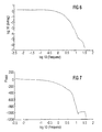
- the found Frequency characteristics, d. H. the amount characteristic with respect to the Amplitude and frequency and the phase characteristic with respect the frequency normalized.
- This standardization has in the floor diagram the effect of a simple shift of the Frequency characteristics. That serves as the standardization variable Frequency at which the phase characteristic takes the value -100 °, and the corresponding one Amount of the amount characteristic.
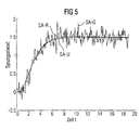
- the step response is now first smoothed according to the invention, the fact being used for smoothing that the step response im to determine a point of the smoothed curve entire history is available.
- the step response can be differentiated, which gives an estimate of the route impulse response.
- the estimated impulse response now forms the basis for determining the frequency characteristics of the controlled system in a manner analogous to the methods presented in (3 , 4) . This method still delivers good results even in the event of strong disturbances in the step response.
- the two operations mentioned can be formulated in matrix notation and combined into a single matrix multiplication with a complex matrix.
- the second option is the smoothed impulse response the route by unfolding the response signal with respect to the Input signal calculated. This deployment operation hangs on the input signal. If the input signal is abrupt, so the deconvolution operation is identical to a smoothing and subsequent differentiation.
- the second method represents so a generalization of the smoothing process a smoothing unfolding.
- the rest of the presentation is done using the Step response from the controlled system when a Jump signal is given.
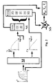
- FIG. 1 shows the structure of a control loop, consisting of a controlled system RS and a controller RG. It should be a PID controller RG.
- the controlled system RS is shown again symbolically, here a jump signal SS is supplied in the invention, it generates a jump response SA based on the jump signal, the amplitude y of which is plotted against the time t.
- a neural network NN Before a neural network NN can generate parameters Kp, Tn, Tv for setting the controller RG, it must be trained beforehand. Tn is the reset time, Tv is the lead time and Kp is the proportional factor (1) .
- the neural network NN is trained using a Teacher LR, using one of the above methods adjusts the weights of the neural network so that those of the Teacher LR and the neural network due to a step response delivered values become approximately identical.
- the teacher LR are usually fed the route parameters directly. But other sizes can also be used for unambiguous characterization the route are processed.
- the teacher adjusts the weights of the neural network NN, until no further reduction of the deviation is possible is.
- the training of the neural network NN is not the subject of the present invention, it can be known Sort of.
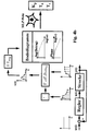
- C, D, E, F are formed, which are supplied as input variables to the neural network NN.
- the parameter G is calculated directly from the response and is also fed to the neural network NN.
- the neural network NN Based on these input variables, the neural network NN generates the controller parameters Kp, Tn, Tv. These controller parameters Kp, Tn, Tv are used to set the PID controller, which is such that the control loop works properly.
- T is the sampling time.
- the discrete-time signal y (n) can now be combined into a vector
- a T D a should be as small as possible.
- the first term evaluates the deviation of the approximation from the measured step response and the second term the roughness of the approximation.
- X ⁇ v ⁇ denotes a convolution integration operator of v (t) with the input signal x (t).
- a convolution matrix X can be formed from this by approximating the integration with a sum.
- the smoothed impulse response is now determined not by minimizing the energy function G1 (7), but by minimizing the expanded energy function
- the vector characterizing the impulse response can thus be determined from the vector y of the measured output signal in the same way as in the case of abrupt excitation by means of an ordinary matrix multiplication.
- the matrix V now depends on the input signal x (t) because the matrix X depends on the input signal.
- the frequency characteristics shown in FIGS. 6 and 7 can thus be obtained directly by matrix multiplications of the vector y with a fixed matrix which has been calculated in advance.
Landscapes
- Engineering & Computer Science (AREA)
- Physics & Mathematics (AREA)
- Automation & Control Theory (AREA)
- General Physics & Mathematics (AREA)
- Computer Vision & Pattern Recognition (AREA)
- Medical Informatics (AREA)
- Software Systems (AREA)
- Evolutionary Computation (AREA)
- Health & Medical Sciences (AREA)
- Artificial Intelligence (AREA)
- Feedback Control In General (AREA)
- Indexing, Searching, Synchronizing, And The Amount Of Synchronization Travel Of Record Carriers (AREA)
- Control Of Electric Motors In General (AREA)
Claims (20)
- Procédé d'obtention de paramètres de réglage à partir d'un signal de réponse d'un système commandé au moyen d'un calculateur,dans lequel le signal d'entrée et le signal de réponse sont analysés,dans lequel le signal d'entrée et le signal de réponse analysés sont lissés au moyen d'un filtre variable en temps ou sont lissés et différentiés au moyen du filtre variable en temps,dans lequel les courbes caractéristiques de fréquence sont produites, à chaque fois, à partir du signal d'entrée et du signal de réponse lissés ou lissés et différentiés,dans lequel on forme une différence des courbes caractéristiques de fréquence dans le diagramme de Bode,dans lequel on détermine les paramètres de réglage en se basant sur la différence.
- Procédé d'obtention de paramètres de réglage à partir d'un signal de réponse d'un système commandé au moyen d'un calculateur,dans lequel le signal d'entrée et le signal de réponse sont analysés,dans lequel on produit, à partir du signal de réponse analysé, une réponse lissée impulsionnelle par déconvolution du signal de réponse par rapport au signal d'entrée,dans lequel les courbes caractéristiques de fréquence dans le diagramme de Bode sont formées à partir de la réponse impulsionnelle,dans lequel on détermine les paramètres de réglage en se basant sur les courbes caractéristiques de fréquence.
- Procédé d'obtention de paramètres de réglage à partir d'un signal de réponse d'un système commandé au moyen d'un calculateur,dans lequel le signal de réponse est analysé,dans lequel le signal de réponse analysé est lissé au moyen d'un filtre variable en temps ou est lissé et différentié au moyen du filtre variable en temps,dans lequel les courbes caractéristiques de fréquence sont produites dans un diagramme de Bode à partir du signal de réponse lissé ou lissé et différentié,dans lequel on détermine les paramètres de réglage en se basant sur les courbes caractéristiques de fréquence.
- Procédé selon l'une des revendications 1, 2 ou 3, dans lequel la déconvolution, le lissage ou le lissage et la différentiation du signal d'entrée ou signal de réponse et l'obtention de la réponse impulsionnelle se font suivant la formule
 y signifiant un vecteur formé par les valeurs d'analyse du signal de réponse, V la matrice pour la déconvolution ou le lissage ou le lissage et la différentiation, v le vecteur de la réponse impulsionnelle lissée, x le vecteur du signal d'entrée,
- Procédé selon la revendication 4 en liaison avec la revendication 2, dans lequel la matrice de déconvolution est obtenue à partir d'une fonction d'énergie qui comprend un terme indiquant l'écart entre l'approximation et le signal de réponse mesuré et comprend un terme indiquant l'irrégularité de la réponse impulsionnelle restituée.
- Procédé selon la revendication 5, dans lequel la matrice de déconvolution lissante V est obtenue par minimisation de la fonction d'énergie suivante :où
 dans lequel la solution de cette minimisation estk est une constante, par exemple 0,5,X est une matrice d'intégration de convolution qui est calculée en fonction du signal d'entrée x(t),A est une matrice d'intégration,r = A b, a = A r, v= A aet D 0, D 1, D 2,..., D 4 sont des matrices diagonales pouvant être choisies de manière quelconque,
 - Procédé selon la revendication 4 en liaison avec la revendication 1, dans lequel la matrice V pour le lissage et la différentiation est obtenue à partir d'une fonction d'énergie qui comprend un terme indiquant l'écart entre l'approximation et le signal de réponse mesuré et comprend un terme indiquant l'irrégularité de la réponse impulsionnelle restituée.
- Procédé selon la revendication 7, dans lequel la matrice V pour le lissage ou le lissage et la différentiation est formulée de la manière suivante :D 1,..., D 4 signifiant une matrice diagonale pouvant être choisie de manière quelconque,A une matrice d'intégration,T la transposition.
- Procédé selon la revendication 4 en liaison avec la revendication 3, dans lequel la matrice V pour le lissage et la différentiation est obtenue à partir d'une fonction d'énergie qui comprend un terme indiquant l'écart entre l'approximation et le signal de réponse mesuré et comprend un terme indiquant l'irrégularité de la réponse impulsionnelle restituée.
- Procédé selon la revendication 9, dans lequel la matrice de lissage ou matrice de lissage et de différentiation est obtenue à partir de la fonction d'énergiele premier terme indiquant l'écart entre l'approximation et le signal de réponse mesuré, le second terme indiquant l'irrégularité de l'approximation, s = A v, v = A a et s = A 2 a, D étant une matrice diagonale, A une matrice d'intégration et k une constante, par exemple 0,5.

- Procédé selon la revendication 9, dans lequel la matrice de lissage ou matrice de lissage et de différentiation est obtenue à partir de la fonction d'énergieD 1, ..., D étant des matrices diagonales, A une matrice d'intégration et les égalités

- Procédé selon l'une des revendications précédentes, dans lequel le diagramme de Bode est normalisé par rapport à la fréquence.
- Procédé selon la revendication 12, dans lequel la normalisation intervient au niveau de la fréquence à laquelle la courbe caractéristique de phase prend la valeur -ΦN.
- Procédé selon l'une des revendications précédentes, dans lequel les caractéristiques du diagramme de Bode sont formées selon la méthode de l'approximation d'une réponse à un échelon ou d'une réponse impulsionnelle par un tracé polygonal ou par des blocs rectangulaires et la transformation en la gamme de fréquences se fait au moyen de correspondances élémentaires.
- Procédé selon la revendication 14, dans lequel, pour l'approximation de la réponse fréquentielle, la formuleest vérifiée.

- Procédé selon la revendication 15, dans lequel l'approximation de la réponse fréquentielle est obtenue à partir du vecteur y par la formuleet la formule
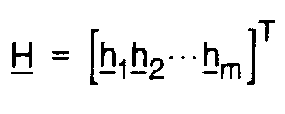 étant vérifiée.
- Système pour le réglage adaptatif d'un régulateur PID à l'aide d'un réseau neuronal d'après le procédé selon l'une des revendications 4, 7, 8, 12-16,dans lequel on prévoit des premiers moyens d'analyse d'un signal de réponse délivré par un système commandé sur la base d'un signal d'entrée amené,dans lequel on prévoit à chaque fois des moyens de transformation (M) grâce auxquels le signal d'entrée et le signal de réponse (SA) sont lissés, le cas échéant différentiés, et transformés en la gamme de fréquences,dans lequel, pour obtenir le diagramme de Bode du système commandé, on forme la différence des courbes caractéristiques de fréquence du signal d'entrée et du signal de réponse dans le diagramme de Bode,dans lequel le diagramme de Bode - non seulement la courbe caractéristique de valeur mais également la courbe caractéristique de phase - est appliqué au réseau neuronal, directement ou après conversion, en tant que valeurs d'entrée,dans lequel le réseau neuronal délivre des paramètres destinés au réglage du régulateur.
- Système pour le réglage adaptatif d'un régulateur PID à l'aide d'un réseau neuronal d'après le procédé selon l'une des revendications 4-6, 12-16,dans lequel on prévoit des premiers moyens d'analyse d'un signal de réponse délivré par un système commandé sur la base d'un signal d'entrée amené,dans lequel on prévoit des moyens de déconvolution grâce auxquels on évalue la réponse impulsionnelle lissée à partir du signal de réponse en fonction du signal d'entrée,dans lequel on prévoit des seconds moyens permettant d'obtenir le diagramme de Bode du système commandé à partir de la réponse impulsionnelle lissée,dans lequel le diagramme de Bode - non seulement la courbe caractéristique de valeur mais également la courbe caractéristique de phase - est appliqué au réseau neuronal, directement ou après conversion, en tant que valeurs d'entrée,dans lequel le réseau neuronal délivre des paramètres destinés au réglage du régulateur.
- Système pour le réglage adaptatif d'un régulateur PID à l'aide d'un réseau neuronal d'après le procédé selon l'une des revendications 4, 9, 12-16,dans lequel on prévoit des premiers moyens d'analyse d'un signal de réponse délivré par un système commandé sur la base d'un signal d'entrée amené,dans lequel on prévoit des moyens de transformation (M) grâce auxquels le signal de réponse (SA) est lissé, le cas échéant différentié, et transformé en la gamme de fréquences,dans lequel on prévoit des seconds moyens permettant d'obtenir le diagramme de Bode à partir du signal de réponse lissé,dans lequel le diagramme de Bode - non seulement la courbe caractéristique de valeur mais également la courbe caractéristique de phase - est appliqué au réseau neuronal, directement ou après conversion, en tant que valeurs d'entrée,dans lequel le réseau neuronal délivre des paramètres destinés au réglage du régulateur.
- Système selon l'une des revendications 17, 18 ou 19, dans lequel on prévoit une unité de normalisation (NE) pour normaliser le diagramme de Bode par rapport à la fréquence.
Applications Claiming Priority (3)
| Application Number | Priority Date | Filing Date | Title |
|---|---|---|---|
| DE19604793 | 1996-02-09 | ||
| DE19604793 | 1996-02-09 | ||
| PCT/DE1997/000242 WO1997029411A1 (fr) | 1996-02-09 | 1997-02-07 | Procede d'obtention de parametres de reglage a partir d'un signal de reponse d'un systeme commande au moyen d'un calculateur |
Publications (2)
| Publication Number | Publication Date |
|---|---|
| EP0879447A1 EP0879447A1 (fr) | 1998-11-25 |
| EP0879447B1 true EP0879447B1 (fr) | 1999-11-17 |
Family
ID=7784988
Family Applications (1)
| Application Number | Title | Priority Date | Filing Date |
|---|---|---|---|
| EP97914132A Expired - Lifetime EP0879447B1 (fr) | 1996-02-09 | 1997-02-07 | Procede d'obtention de parametres de reglage a partir d'un signal de reponse d'un systeme commande au moyen d'un calculateur |
Country Status (9)
| Country | Link |
|---|---|
| US (1) | US6353766B1 (fr) |
| EP (1) | EP0879447B1 (fr) |
| AT (1) | ATE186786T1 (fr) |
| CZ (1) | CZ250498A3 (fr) |
| DE (1) | DE59700720D1 (fr) |
| ES (1) | ES2140223T3 (fr) |
| HU (1) | HUP9901407A3 (fr) |
| PL (1) | PL328426A1 (fr) |
| WO (1) | WO1997029411A1 (fr) |
Families Citing this family (15)
| Publication number | Priority date | Publication date | Assignee | Title |
|---|---|---|---|---|
| US6725208B1 (en) * | 1998-10-06 | 2004-04-20 | Pavilion Technologies, Inc. | Bayesian neural networks for optimization and control |
| US8280533B2 (en) * | 2000-06-20 | 2012-10-02 | Fisher-Rosemount Systems, Inc. | Continuously scheduled model parameter based adaptive controller |
| US7113834B2 (en) * | 2000-06-20 | 2006-09-26 | Fisher-Rosemount Systems, Inc. | State based adaptive feedback feedforward PID controller |
| DE102004058238B4 (de) * | 2003-12-03 | 2016-02-04 | Fisher-Rosemount Systems, Inc. | Adaptive, multivariable Prozesssteuerung, die Modellschaltung und Attribut-Interpolation nutzt |
| US20050165590A1 (en) * | 2004-01-23 | 2005-07-28 | Yuhong Huang | System and method for virtual laser marking |
| US7499763B2 (en) * | 2005-07-20 | 2009-03-03 | Fuel And Furnace Consulting, Inc. | Perturbation test method for measuring output responses to controlled process inputs |
| US8036760B2 (en) | 2005-10-04 | 2011-10-11 | Fisher-Rosemount Systems, Inc. | Method and apparatus for intelligent control and monitoring in a process control system |
| US7738975B2 (en) * | 2005-10-04 | 2010-06-15 | Fisher-Rosemount Systems, Inc. | Analytical server integrated in a process control network |
| US7444191B2 (en) | 2005-10-04 | 2008-10-28 | Fisher-Rosemount Systems, Inc. | Process model identification in a process control system |
| DE102010042625B4 (de) | 2010-10-19 | 2023-09-28 | Dr. Johannes Heidenhain Gmbh | Verfahren zum Bestimmen eines Bode-Diagramms |
| DE102013205356B4 (de) * | 2013-03-26 | 2016-07-07 | Siemens Aktiengesellschaft | Verfahren zur rechnergestützten Steuerung und/oder Regelung eines technischen Systems |
| DE102014222457A1 (de) * | 2014-11-04 | 2016-05-04 | Schaeffler Technologies AG & Co. KG | Verfahren zur Ermittlung eines Übertragungsverhaltens eines Antriebsstrangs |
| CN109459927A (zh) * | 2019-01-16 | 2019-03-12 | 中国科学院光电技术研究所 | 基于神经网络的pid控制器参数整定方法 |
| CN114185358B (zh) * | 2021-11-30 | 2024-04-12 | 中国电子科技集团公司第五十四研究所 | 一种卫星导航接收机自适应信号跟踪方法 |
| CN120750412B (zh) * | 2025-09-02 | 2026-01-02 | 银河航天(西安)科技有限公司 | 针对卫星激光链路的通信质量提升方法、装置及存储介质 |
Citations (1)
| Publication number | Priority date | Publication date | Assignee | Title |
|---|---|---|---|---|
| EP0520233A2 (fr) * | 1991-06-24 | 1992-12-30 | Siemens Aktiengesellschaft | Dispositif pour l'identification d'un système commandé |
Family Cites Families (6)
| Publication number | Priority date | Publication date | Assignee | Title |
|---|---|---|---|---|
| JPH0354602A (ja) * | 1989-07-22 | 1991-03-08 | Nobuo Yamamoto | 制御系の時間差比較2自由度制御方法及び装置 |
| CA2118598C (fr) * | 1991-12-18 | 2004-04-13 | Anoop K. Mathur | Syntoniseur automatique pour reseau neuronal a boucle fermee |
| US5379210A (en) * | 1992-07-24 | 1995-01-03 | M&M Software Products, Inc. | Natural tracking controller |
| GB2271909B (en) * | 1992-10-21 | 1996-05-22 | Lotus Car | Adaptive control system |
| US5633795A (en) * | 1995-01-06 | 1997-05-27 | Digisonix, Inc. | Adaptive tonal control system with constrained output and adaptation |
| JP3751359B2 (ja) * | 1996-03-21 | 2006-03-01 | 本田技研工業株式会社 | 振動騒音制御装置 |
-
1997
- 1997-02-07 EP EP97914132A patent/EP0879447B1/fr not_active Expired - Lifetime
- 1997-02-07 ES ES97914132T patent/ES2140223T3/es not_active Expired - Lifetime
- 1997-02-07 DE DE59700720T patent/DE59700720D1/de not_active Expired - Lifetime
- 1997-02-07 AT AT97914132T patent/ATE186786T1/de not_active IP Right Cessation
- 1997-02-07 HU HU9901407A patent/HUP9901407A3/hu unknown
- 1997-02-07 CZ CZ982504A patent/CZ250498A3/cs unknown
- 1997-02-07 WO PCT/DE1997/000242 patent/WO1997029411A1/fr not_active Ceased
- 1997-02-07 PL PL97328426A patent/PL328426A1/xx unknown
-
1998
- 1998-08-10 US US09/132,083 patent/US6353766B1/en not_active Expired - Fee Related
Patent Citations (1)
| Publication number | Priority date | Publication date | Assignee | Title |
|---|---|---|---|---|
| EP0520233A2 (fr) * | 1991-06-24 | 1992-12-30 | Siemens Aktiengesellschaft | Dispositif pour l'identification d'un système commandé |
Also Published As
| Publication number | Publication date |
|---|---|
| HUP9901407A3 (en) | 1999-12-28 |
| DE59700720D1 (de) | 1999-12-23 |
| CZ250498A3 (cs) | 1999-01-13 |
| WO1997029411A1 (fr) | 1997-08-14 |
| ATE186786T1 (de) | 1999-12-15 |
| EP0879447A1 (fr) | 1998-11-25 |
| PL328426A1 (en) | 1999-02-01 |
| HUP9901407A2 (hu) | 1999-08-30 |
| US6353766B1 (en) | 2002-03-05 |
| ES2140223T3 (es) | 2000-02-16 |
Similar Documents
| Publication | Publication Date | Title |
|---|---|---|
| EP0879447B1 (fr) | Procede d'obtention de parametres de reglage a partir d'un signal de reponse d'un systeme commande au moyen d'un calculateur | |
| DE69425140T2 (de) | Adaptives steuerungssystem im frequenzbereich | |
| DE69128996T2 (de) | Identifizierung eines Prozesssystems | |
| DE69607168T2 (de) | Verfahren zur sensorfehlererkennung | |
| EP3732458B1 (fr) | Banc d'essai et procédé pour un essai dynamique | |
| DE10304902B4 (de) | Anpassung von erweiterten Prozeßsteuerblöcken in Abhängigkeit von veränderlichen Prozeßverzögerungen | |
| DE60316517T2 (de) | Verfahren und Vorrichtung zur Aufnahme von Störsignalen | |
| DE69002233T2 (de) | Vorrichtung und verfahren zur eichung eines fühlersystems. | |
| DE19531967C2 (de) | Verfahren zum Training eines neuronalen Netzes mit dem nicht deterministischen Verhalten eines technischen Systems | |
| DE3852289T2 (de) | Adaptive störgrössenaufschaltung in einem regelsystem mit rückführung. | |
| EP3065250A1 (fr) | Procede et dispositif de determination de la topologie d'un reseau d'alimentation en electricite | |
| EP0520233B1 (fr) | Dispositif pour l'identification d'un système commandé | |
| EP1052558A1 (fr) | Procédé et dispositif d'estimation d' état | |
| DE69304692T2 (de) | Verfahren zur schnellen kalman-filterung in grossen dynamischen systemen | |
| DE2009071A1 (de) | Quantisierungsanlage mit anpassungsfähiger automatischer Festzeichenunterdrückung | |
| DE69326420T2 (de) | Digitale Verarbeitung und Filterung von Signalen | |
| DE3884542T2 (de) | Adaptive mehrgrössensteuerung. | |
| WO2018091592A1 (fr) | Dispositif et procédé de détermination des paramètres d'un dispositif de régulation | |
| DE3904736A1 (de) | Verfahren zum abstimmen der lagesteuereinheit eines aufzugs | |
| EP1512207B1 (fr) | Interrupteur de protection contre les courants de fuite | |
| DE1523535C3 (de) | Selbstanpassender Regelkreis | |
| DE4319926C2 (de) | Verfahren zur Regelung eines kontinuierlichen Prozesses mit einer Optimier- und einer Regelphase | |
| DE3929615A1 (de) | Adaptiver regler | |
| DE102016221966A1 (de) | Verfahren zum Ansteuern einer Aktoreinrichtung und mikromechanische Vorrichtung | |
| EP3739400A1 (fr) | Évaluation successive des réponses en fréquence |
Legal Events
| Date | Code | Title | Description |
|---|---|---|---|
| PUAI | Public reference made under article 153(3) epc to a published international application that has entered the european phase |
Free format text: ORIGINAL CODE: 0009012 |
|
| 17P | Request for examination filed |
Effective date: 19980805 |
|
| AK | Designated contracting states |
Kind code of ref document: A1 Designated state(s): AT CH DE ES FR GB LI |
|
| 17Q | First examination report despatched |
Effective date: 19981127 |
|
| GRAG | Despatch of communication of intention to grant |
Free format text: ORIGINAL CODE: EPIDOS AGRA |
|
| GRAG | Despatch of communication of intention to grant |
Free format text: ORIGINAL CODE: EPIDOS AGRA |
|
| GRAH | Despatch of communication of intention to grant a patent |
Free format text: ORIGINAL CODE: EPIDOS IGRA |
|
| GRAH | Despatch of communication of intention to grant a patent |
Free format text: ORIGINAL CODE: EPIDOS IGRA |
|
| GRAA | (expected) grant |
Free format text: ORIGINAL CODE: 0009210 |
|
| AK | Designated contracting states |
Kind code of ref document: B1 Designated state(s): AT CH DE ES FR GB LI |
|
| REF | Corresponds to: |
Ref document number: 186786 Country of ref document: AT Date of ref document: 19991215 Kind code of ref document: T |
|
| REG | Reference to a national code |
Ref country code: CH Ref legal event code: NV Representative=s name: SIEMENS SCHWEIZ AG Ref country code: CH Ref legal event code: EP |
|
| REF | Corresponds to: |
Ref document number: 59700720 Country of ref document: DE Date of ref document: 19991223 |
|
| ET | Fr: translation filed | ||
| GBT | Gb: translation of ep patent filed (gb section 77(6)(a)/1977) |
Effective date: 20000120 |
|
| REG | Reference to a national code |
Ref country code: ES Ref legal event code: FG2A Ref document number: 2140223 Country of ref document: ES Kind code of ref document: T3 |
|
| PLBE | No opposition filed within time limit |
Free format text: ORIGINAL CODE: 0009261 |
|
| STAA | Information on the status of an ep patent application or granted ep patent |
Free format text: STATUS: NO OPPOSITION FILED WITHIN TIME LIMIT |
|
| 26N | No opposition filed | ||
| REG | Reference to a national code |
Ref country code: GB Ref legal event code: IF02 |
|
| PGFP | Annual fee paid to national office [announced via postgrant information from national office to epo] |
Ref country code: ES Payment date: 20050216 Year of fee payment: 9 |
|
| PGFP | Annual fee paid to national office [announced via postgrant information from national office to epo] |
Ref country code: CH Payment date: 20050509 Year of fee payment: 9 |
|
| PGFP | Annual fee paid to national office [announced via postgrant information from national office to epo] |
Ref country code: AT Payment date: 20060118 Year of fee payment: 10 |
|
| PG25 | Lapsed in a contracting state [announced via postgrant information from national office to epo] |
Ref country code: ES Free format text: LAPSE BECAUSE OF NON-PAYMENT OF DUE FEES Effective date: 20060208 |
|
| PG25 | Lapsed in a contracting state [announced via postgrant information from national office to epo] |
Ref country code: LI Free format text: LAPSE BECAUSE OF NON-PAYMENT OF DUE FEES Effective date: 20060228 Ref country code: CH Free format text: LAPSE BECAUSE OF NON-PAYMENT OF DUE FEES Effective date: 20060228 |
|
| REG | Reference to a national code |
Ref country code: CH Ref legal event code: PL |
|
| REG | Reference to a national code |
Ref country code: ES Ref legal event code: FD2A Effective date: 20060208 |
|
| PG25 | Lapsed in a contracting state [announced via postgrant information from national office to epo] |
Ref country code: AT Free format text: LAPSE BECAUSE OF NON-PAYMENT OF DUE FEES Effective date: 20070207 |
|
| PGFP | Annual fee paid to national office [announced via postgrant information from national office to epo] |
Ref country code: DE Payment date: 20120420 Year of fee payment: 16 |
|
| PGFP | Annual fee paid to national office [announced via postgrant information from national office to epo] |
Ref country code: GB Payment date: 20130213 Year of fee payment: 17 Ref country code: FR Payment date: 20130301 Year of fee payment: 17 |
|
| REG | Reference to a national code |
Ref country code: DE Ref legal event code: R119 Ref document number: 59700720 Country of ref document: DE Effective date: 20130903 |
|
| PG25 | Lapsed in a contracting state [announced via postgrant information from national office to epo] |
Ref country code: DE Free format text: LAPSE BECAUSE OF NON-PAYMENT OF DUE FEES Effective date: 20130903 |
|
| GBPC | Gb: european patent ceased through non-payment of renewal fee |
Effective date: 20140207 |
|
| REG | Reference to a national code |
Ref country code: FR Ref legal event code: ST Effective date: 20141031 |
|
| PG25 | Lapsed in a contracting state [announced via postgrant information from national office to epo] |
Ref country code: FR Free format text: LAPSE BECAUSE OF NON-PAYMENT OF DUE FEES Effective date: 20140228 Ref country code: GB Free format text: LAPSE BECAUSE OF NON-PAYMENT OF DUE FEES Effective date: 20140207 |