EP0879498B1 - Actionneur electromagnetique lineaire a deux rotors vibrant en opposition de phase - Google Patents
Actionneur electromagnetique lineaire a deux rotors vibrant en opposition de phase Download PDFInfo
- Publication number
- EP0879498B1 EP0879498B1 EP97900658A EP97900658A EP0879498B1 EP 0879498 B1 EP0879498 B1 EP 0879498B1 EP 97900658 A EP97900658 A EP 97900658A EP 97900658 A EP97900658 A EP 97900658A EP 0879498 B1 EP0879498 B1 EP 0879498B1
- Authority
- EP
- European Patent Office
- Prior art keywords
- electromagnetic actuator
- linear electromagnetic
- cylindrical
- actuator according
- movable
- Prior art date
- Legal status (The legal status is an assumption and is not a legal conclusion. Google has not performed a legal analysis and makes no representation as to the accuracy of the status listed.)
- Expired - Lifetime
Links
- 230000005294 ferromagnetic effect Effects 0.000 claims description 9
- 239000011324 bead Substances 0.000 claims 1
- 238000005452 bending Methods 0.000 description 1
- 230000004087 circulation Effects 0.000 description 1
- KPLQYGBQNPPQGA-UHFFFAOYSA-N cobalt samarium Chemical compound [Co].[Sm] KPLQYGBQNPPQGA-UHFFFAOYSA-N 0.000 description 1
- 230000000295 complement effect Effects 0.000 description 1
- 238000006073 displacement reaction Methods 0.000 description 1
- 239000003302 ferromagnetic material Substances 0.000 description 1
- 230000004907 flux Effects 0.000 description 1
- 230000010354 integration Effects 0.000 description 1
- 238000004519 manufacturing process Methods 0.000 description 1
- 238000000034 method Methods 0.000 description 1
- QEFYFXOXNSNQGX-UHFFFAOYSA-N neodymium atom Chemical compound [Nd] QEFYFXOXNSNQGX-UHFFFAOYSA-N 0.000 description 1
- 244000045947 parasite Species 0.000 description 1
- 229910052761 rare earth metal Inorganic materials 0.000 description 1
- 150000002910 rare earth metals Chemical class 0.000 description 1
- 238000011084 recovery Methods 0.000 description 1
- 229910000938 samarium–cobalt magnet Inorganic materials 0.000 description 1
Images




Classifications
-
- H—ELECTRICITY
- H02—GENERATION; CONVERSION OR DISTRIBUTION OF ELECTRIC POWER
- H02K—DYNAMO-ELECTRIC MACHINES
- H02K33/00—Motors with reciprocating, oscillating or vibrating magnet, armature or coil system
- H02K33/16—Motors with reciprocating, oscillating or vibrating magnet, armature or coil system with polarised armatures moving in alternate directions by reversal or energisation of a single coil system
Definitions
- the present invention relates to an actuator linear electromagnetic with an excited stator by at least one electric coil, two moving parts in phase opposition and at least one permanent magnet.
- the goal is to reduce the level of vibrations by proposing a structure where the sum of momentum of moving masses is zero.
- the object of the present invention is to propose an improved actuator compared to the state of technique, and particularly in terms of reduction of transverse dimensions and mechanical integration. In particular, it aims to make a low vibration actuator compact parasites, low manufacturing cost and very robust.
- the invention relates to a actuator.
- the two pieces mobile ferromagnets are semi-cylindrical in shape.
- the two pieces ferromagnetic have identical masses.
- the stator has two cylindrical stator poles supported by a tubular casing.
- a tubular casing By cylindrical, we will hear any form generated by displacement of a generator along a shape path any, including circular, rectangular or square. In the particular case of a circular path, the shape will be annular.
- the two stator poles cylindrical are arranged so that the two moving parts define with cylindrical poles opposite semi-cylindrical air gaps of section depending on their position.
- the recovery of the part mobile on the upper stator varies depending on the position of the moving part.
- the length L of the moving parts is substantially equal to the distance D separating the two cylindrical poles plus the thickness 1 of a cylindrical pole.
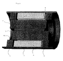
- Figures 1 and 2 show views in respectively longitudinal and cross section of a actuator according to the invention.
- the actuator has a thin magnet (1) placed in a longitudinal median plane (20).
- the magnet is of the "rare earth” type, for example Samarium-cobalt or Neodyme, and is magnetized transversely, in the thickness direction, either perpendicular to the median plane (20).
- the magnet (1) is fixed relative to the stator, and is arranged between two moving parts (2, 3) consisting of half-cylinders made of ferromagnetic material. These two moving parts (2, 3) are symmetrical with respect to the median plane (20).
- the stator is made up of two poles stator (8, 5) of cylindrical shape between which is arranged a cylindrical coil (4).
- the coil cylindrical (4) is wound on a coil body (11) which also supports the fixed magnet (1).
- the two stator poles (5, 8) are magnetically connected by an outer yoke (7) tubular.
- the moving part (3) When the moving part (3) is in position low, it defines with the lower stator pole (5) a semi-cylindrical air gap (10) of large section.
- the second movable part (2) is in high position, and defines with the stator pole upper (8) a semi-cylindrical air gap (9) of section substantially identical to that of the air gap (10) opposite.
- the air gap sections (3, 9) are identical and vary continuously depending on the position of moving parts. Sections are maximum at the end of travel of the moving parts (2, 3).
- stator poles cylindrical (8, 5) have a thickness 1 of 2 millimeters and are spaced 10.5 millimeters apart.
- the length of the coil is 9.5 millimeters.
- the length of the moving parts (2, 3) is 12.5 millimeters, or substantially the value of the distance between the two stator poles increased by the thickness of a stator pole.
- the length of the magnet (1) is substantially equal to the length of the coil (4) or 10.5 millimeters.
- Elastic blades (12, 13) arranged at each end of the actuator ensures the positioning of the moving parts (2, 3) and their guidance without friction.
- a alternating current for example sinusoidal or square
- Figures 3 and 4 show views exploded view of the actuator in two opposite positions: In the position illustrated in FIG. 3, the part mobile (2) is in the high position and the mobile part (3) is in the down position.
- the field line shown in the figure 3 closes successively through the air gap (9) defined by the upper stator pole (8) and the upper end of the moving part (2) in high position, the upper stator pole (8), the tubular outer cylinder head (7), the stator pole lower (5), the air gap (10) defines between the pole lower stator (5) and the lower end of the second movable part (3) in the low position and finally through the magnet (1).
- Figures 5 and 6 show a first variant in which the leaf springs are replaced by balls. Guiding the pieces mobile (2, 3) is made by balls (40 to 46) or cylindrical needles housed in cavities of complementary shape provided in the supporting frame the fixed magnet (1).
- FIGS 7 and 8 show a second variant.
- Each moving part is constituted by a ferromagnetic tile (22, 23) on which is stuck a magnet respectively (21, 20) in thin tile shape.
- the two shaped magnets (20, 21) of tiles are magnetized in the thickness direction, according to identical orientations, and each generate a flux passing through the cylindrical coil (29) wound on a plastic body (28).
- the forces exerted on each moving parts are in opposite directions, and the part mobile (21, 22) tends to increase the cross-section of the air gap (27) which it forms with the stator pole (24) by moving down.
- the movable part formed of the part ferromagnetic (23) on which the magnet is fixed (20) tends to increase the cross-section of the air gap (26) that it forms with the stator pole (25) while moving up.
- the movement of each of the moving parts is reversed.
- nucleus ferromagnetic (30) which conducts the flow of each magnet towards the poles (24, 25) sees circulations of opposite flow for each moving part, which has tendency to lower the saturation level in said core (30), therefore allows the use of a coil of smaller inside diameter providing more ampere-turns for a given electrical power.
- the moving parts are suspended by blades of bending (31, 32).
Landscapes
- Engineering & Computer Science (AREA)
- Power Engineering (AREA)
- Reciprocating, Oscillating Or Vibrating Motors (AREA)
Description
- la figure 1 représente une vue en coupe longitudinale d'un actionneur selon l'invention ;
- la figure 2 représente une vue en coupe transversale d'un actionneur selon l'invention ;
- les figures 3 et 4 représentent des vues éclatées de l'actionneur, dans deux positions opposées ;
- la figure 5 représente une vue en coupe longitudinale d'une première variante de l'actionneur selon l'invention ;
- la figure 6 représente une vue en coupe transversale d'une première variante de l'actionneur selon l'invention ;
- la figure 7 représente une vue en coupe longitudinale d'une deuxième variante de l'actionneur selon l'invention ;
- la figure 8 représente une vue en coupe transversale d'une deuxième variante de l'actionneur selon l'invention.
Claims (10)
- Actionneur électromagnétique linéaire comportant un stator excité par au moins une bobine électrique (4, 29), deux pièces mobiles (2, 3) ou (22, 23) en opposition et au moins un aimant mince permanent (1, ou 20, 21) aimanté dans le sens de l'épaisseur, caractérisé en ce que le stator présente deux pôles statoriques cylindriques (5, 8) ou (24, 25) entre lesquels est logée la bobine cylindrique (4, 29), et en ce que les pièces mobiles (2, 3) ou (22, 23) sont des pièces ferromagnétiques disposées d'une manière propre à définir avec les pôles statoriques cylindriques (5, 8) ou (24, 25) des entrefers de section variable, la somme des sections de deux entrefers formés à une extrémité frontale de l'actionneur étant constante.
- Actionneur électromagnétique linéaire selon la revendication 1 caractérisé en ce que l'aimant permanent mince (1) est un aimant plan disposé dans le plan de symétrie longitudinal médian, les deux pièces mobiles (2, 3) étant des pièces ferromagnétiques disposées de part et d'autre de l'aimant permanent.
- Actionneur électromagnétique linéaire selon la revendication 2 caractérisé en ce les deux pièces ferromagnétiques mobiles ont la forme d'un cylindre de section semi-circulaire.
- Actionneur électromagnétique linéaire selon la revendication 1, 2 ou 3 caractérisé en ce que les deux pièces ferromagnétiques présentent des masses identiques.
- Actionneur électromagnétique linéaire selon l'une quelconque des revendications précédentes caractérisé en ce que le stator comporte deux pôles statoriques annulaires supportés par une enveloppe tubulaire.
- Actionneur électromagnétique linéaire selon la revendication 5 caractérisé en ce que les deux pôles statoriques cylindriques sont disposés d'une façon à ce que les deux pièces mobiles (2, 3) définissent avec les pôles cylindriques opposés des entrefers semi-cylindriques dont la surface varie continûment, linéairement en fonction de la position des pièces mobiles (2, 3).
- Actionneur électromagnétique linéaire selon la revendication 5 ou 6 caractérisé en ce que la longueur L des pièces mobiles (2, 3) est sensiblement égale à la distance D séparant les deux pôles cylindriques plus l'épaisseur 1 d'un pôle cylindrique.
- Actionneur électromagnétique linéaire selon la revendication 1 caractérisé en ce qu'il comporte deux parties mobiles en opposition formée chacune d'une pièce ferromagnétique en forme de tuile associée à un aimant permanent mince (1) en forme de tuile.
- Actionneur électromagnétique linéaire selon l'une quelconque des revendications précédentes caractérisé en ce que les parties mobiles sont suspendues par des lames élastiques.
- Actionneur électromagnétique linéaire selon l'une quelconque des revendications 2 à 7 caractérisé en ce que les parties mobiles sont guidées par des billes ou des aiguilles disposées entre les pièces mobiles (2, 3) et l'aimant plan (1).
Applications Claiming Priority (3)
| Application Number | Priority Date | Filing Date | Title |
|---|---|---|---|
| FR9601515A FR2744576B1 (fr) | 1996-02-07 | 1996-02-07 | Actionneur electromagnetique lineaire a deux rotors vibrant en opposition de phase |
| FR9601515 | 1996-02-07 | ||
| PCT/FR1997/000078 WO1997029534A1 (fr) | 1996-02-07 | 1997-01-16 | Actionneur electromagnetique lineaire a deux rotors vibrant en opposition de phase |
Publications (2)
| Publication Number | Publication Date |
|---|---|
| EP0879498A1 EP0879498A1 (fr) | 1998-11-25 |
| EP0879498B1 true EP0879498B1 (fr) | 2000-04-19 |
Family
ID=9488958
Family Applications (1)
| Application Number | Title | Priority Date | Filing Date |
|---|---|---|---|
| EP97900658A Expired - Lifetime EP0879498B1 (fr) | 1996-02-07 | 1997-01-16 | Actionneur electromagnetique lineaire a deux rotors vibrant en opposition de phase |
Country Status (4)
| Country | Link |
|---|---|
| EP (1) | EP0879498B1 (fr) |
| DE (1) | DE69701727D1 (fr) |
| FR (1) | FR2744576B1 (fr) |
| WO (1) | WO1997029534A1 (fr) |
Families Citing this family (2)
| Publication number | Priority date | Publication date | Assignee | Title |
|---|---|---|---|---|
| CN1079315C (zh) * | 1996-03-26 | 2002-02-20 | 松下电工株式会社 | 往复式电动剃刀 |
| FR2767611B1 (fr) * | 1997-08-22 | 1999-10-29 | Sonceboz | Actionneur electromagnetique a deux pieces mobiles en opposition de phase |
Family Cites Families (3)
| Publication number | Priority date | Publication date | Assignee | Title |
|---|---|---|---|---|
| FR45516E (fr) * | 1934-05-15 | 1935-09-12 | Vibrateur électrique | |
| DE2603681A1 (de) * | 1976-01-31 | 1977-08-04 | Philips Patentverwaltung | Linearmotor, insbesondere fuer unwuchtfreie handgeraete |
| DE3025708A1 (de) * | 1979-07-11 | 1981-01-29 | Lpa Les Produits Associes | Wechselstrom-kleinmotor mit pendelndem laeufer, insbesondere zum antrieb einer zahnbuerste |
-
1996
- 1996-02-07 FR FR9601515A patent/FR2744576B1/fr not_active Expired - Lifetime
-
1997
- 1997-01-16 DE DE69701727T patent/DE69701727D1/de not_active Expired - Lifetime
- 1997-01-16 EP EP97900658A patent/EP0879498B1/fr not_active Expired - Lifetime
- 1997-01-16 WO PCT/FR1997/000078 patent/WO1997029534A1/fr not_active Ceased
Also Published As
| Publication number | Publication date |
|---|---|
| EP0879498A1 (fr) | 1998-11-25 |
| FR2744576A1 (fr) | 1997-08-08 |
| WO1997029534A1 (fr) | 1997-08-14 |
| FR2744576B1 (fr) | 1998-03-20 |
| DE69701727D1 (de) | 2000-05-25 |
Similar Documents
| Publication | Publication Date | Title |
|---|---|---|
| EP0974185B1 (fr) | Actionneur lineaire ameliore | |
| EP0429599B1 (fr) | Actionneur electromagnetique monophase de faible encombrement | |
| EP0592647B1 (fr) | Actionneur electromagnetique a deux pieces mobiles en opposition de phases | |
| EP1005714B1 (fr) | Actionneur electromagnetique a deux pieces mobiles en opposition de phases | |
| EP1811536B1 (fr) | Actionneur magnetique a aimant permanent a volume reduit | |
| EP0713604B1 (fr) | Actionneur electromagnetique monophase a faible course presentant un bon rapport force sur puissance electrique | |
| EP0429625A1 (fr) | Actionneur electromagnetique monophase de faible encombrement. | |
| FR2682542A1 (fr) | Actionneur electromagnetique comportant une structure statorique a trois poles de longueurs differentes et distributeurs pneumatiques mettant en óoeuvre de tels actionneurs. | |
| FR2841683A1 (fr) | Actionneur magnetique | |
| EP0829129A1 (fr) | Actionneur electromagnetique presentant au moins deux positions stables par verrouillage magnetique | |
| WO2015114261A1 (fr) | Actionneur electromagnetique lineaire presentant deux organes mobiles independants | |
| CA2687070A1 (fr) | Actionneur electromagnetique a reluctance variable | |
| FR2744576A1 (fr) | Actionneur electromagnetique lineaire a deux rotors vibrant en opposition de phase | |
| EP0268619B1 (fr) | Dispositif d'actionnement electromagnetique | |
| EP2678924A2 (fr) | Actionneur electromagnetique a densite de force amelioree et application a un rasoir electrique | |
| EP3939151B1 (fr) | Dispositif electromagnetique | |
| EP3729618B1 (fr) | Actionneur a entrainement direct commandé en boucle ouverte | |
| FR2490867A1 (fr) | Electro-aimants au samarium-cobalt et dispositifs de servocommande comprenant ces electro-aimants | |
| FR2756660A1 (fr) | Actionneur electromagnetique pour le deplacement en rotation d'un organe mobile sur une course limitee | |
| FR2811467A1 (fr) | Actionneur de soupape electrodynamique et agencement d'une pluralite de tels actionneurs | |
| EP0779698A1 (fr) | Générateur multipolaire de vibrations électrodynamiques | |
| FR2648637A1 (fr) | Actionneur lineaire electromagnetique | |
| FR2818431A1 (fr) | Dispositif d'entrainement lineaire d'une soupape au moyen d'aimants mobiles |
Legal Events
| Date | Code | Title | Description |
|---|---|---|---|
| PUAI | Public reference made under article 153(3) epc to a published international application that has entered the european phase |
Free format text: ORIGINAL CODE: 0009012 |
|
| 17P | Request for examination filed |
Effective date: 19980807 |
|
| AK | Designated contracting states |
Kind code of ref document: A1 Designated state(s): BE CH DE ES FR GB IT LI LU NL PT SE |
|
| GRAG | Despatch of communication of intention to grant |
Free format text: ORIGINAL CODE: EPIDOS AGRA |
|
| 17Q | First examination report despatched |
Effective date: 19990311 |
|
| GRAG | Despatch of communication of intention to grant |
Free format text: ORIGINAL CODE: EPIDOS AGRA |
|
| GRAH | Despatch of communication of intention to grant a patent |
Free format text: ORIGINAL CODE: EPIDOS IGRA |
|
| GRAH | Despatch of communication of intention to grant a patent |
Free format text: ORIGINAL CODE: EPIDOS IGRA |
|
| GRAA | (expected) grant |
Free format text: ORIGINAL CODE: 0009210 |
|
| AK | Designated contracting states |
Kind code of ref document: B1 Designated state(s): BE CH DE ES FR GB IT LI LU NL PT SE |
|
| PG25 | Lapsed in a contracting state [announced via postgrant information from national office to epo] |
Ref country code: NL Free format text: LAPSE BECAUSE OF FAILURE TO SUBMIT A TRANSLATION OF THE DESCRIPTION OR TO PAY THE FEE WITHIN THE PRESCRIBED TIME-LIMIT Effective date: 20000419 Ref country code: IT Free format text: LAPSE BECAUSE OF FAILURE TO SUBMIT A TRANSLATION OF THE DESCRIPTION OR TO PAY THE FEE WITHIN THE PRESCRIBED TIME-LIMIT;WARNING: LAPSES OF ITALIAN PATENTS WITH EFFECTIVE DATE BEFORE 2007 MAY HAVE OCCURRED AT ANY TIME BEFORE 2007. THE CORRECT EFFECTIVE DATE MAY BE DIFFERENT FROM THE ONE RECORDED. Effective date: 20000419 Ref country code: GB Free format text: LAPSE BECAUSE OF FAILURE TO SUBMIT A TRANSLATION OF THE DESCRIPTION OR TO PAY THE FEE WITHIN THE PRESCRIBED TIME-LIMIT Effective date: 20000419 Ref country code: ES Free format text: THE PATENT HAS BEEN ANNULLED BY A DECISION OF A NATIONAL AUTHORITY Effective date: 20000419 |
|
| REG | Reference to a national code |
Ref country code: CH Ref legal event code: EP |
|
| REF | Corresponds to: |
Ref document number: 69701727 Country of ref document: DE Date of ref document: 20000525 |
|
| PG25 | Lapsed in a contracting state [announced via postgrant information from national office to epo] |
Ref country code: SE Free format text: LAPSE BECAUSE OF FAILURE TO SUBMIT A TRANSLATION OF THE DESCRIPTION OR TO PAY THE FEE WITHIN THE PRESCRIBED TIME-LIMIT Effective date: 20000719 Ref country code: PT Free format text: LAPSE BECAUSE OF FAILURE TO SUBMIT A TRANSLATION OF THE DESCRIPTION OR TO PAY THE FEE WITHIN THE PRESCRIBED TIME-LIMIT Effective date: 20000719 |
|
| PG25 | Lapsed in a contracting state [announced via postgrant information from national office to epo] |
Ref country code: DE Free format text: LAPSE BECAUSE OF FAILURE TO SUBMIT A TRANSLATION OF THE DESCRIPTION OR TO PAY THE FEE WITHIN THE PRESCRIBED TIME-LIMIT Effective date: 20000720 |
|
| NLV1 | Nl: lapsed or annulled due to failure to fulfill the requirements of art. 29p and 29m of the patents act | ||
| GBV | Gb: ep patent (uk) treated as always having been void in accordance with gb section 77(7)/1977 [no translation filed] |
Effective date: 20000419 |
|
| PG25 | Lapsed in a contracting state [announced via postgrant information from national office to epo] |
Ref country code: LU Free format text: LAPSE BECAUSE OF NON-PAYMENT OF DUE FEES Effective date: 20010116 |
|
| PG25 | Lapsed in a contracting state [announced via postgrant information from national office to epo] |
Ref country code: LI Free format text: LAPSE BECAUSE OF NON-PAYMENT OF DUE FEES Effective date: 20010131 Ref country code: CH Free format text: LAPSE BECAUSE OF NON-PAYMENT OF DUE FEES Effective date: 20010131 Ref country code: BE Free format text: LAPSE BECAUSE OF NON-PAYMENT OF DUE FEES Effective date: 20010131 |
|
| PLBE | No opposition filed within time limit |
Free format text: ORIGINAL CODE: 0009261 |
|
| STAA | Information on the status of an ep patent application or granted ep patent |
Free format text: STATUS: NO OPPOSITION FILED WITHIN TIME LIMIT |
|
| 26N | No opposition filed | ||
| BERE | Be: lapsed |
Owner name: S.A. MOVING MAGNET TECHNOLOGIES Effective date: 20010131 |
|
| REG | Reference to a national code |
Ref country code: CH Ref legal event code: PL |
|
| PG25 | Lapsed in a contracting state [announced via postgrant information from national office to epo] |
Ref country code: FR Free format text: LAPSE BECAUSE OF NON-PAYMENT OF DUE FEES Effective date: 20010928 |
|
| REG | Reference to a national code |
Ref country code: FR Ref legal event code: ST |