EP0879509B1 - Liaison optique bidirectionnelle et dispositif d'amplification pour cette liaison - Google Patents
Liaison optique bidirectionnelle et dispositif d'amplification pour cette liaison Download PDFInfo
- Publication number
- EP0879509B1 EP0879509B1 EP97902428A EP97902428A EP0879509B1 EP 0879509 B1 EP0879509 B1 EP 0879509B1 EP 97902428 A EP97902428 A EP 97902428A EP 97902428 A EP97902428 A EP 97902428A EP 0879509 B1 EP0879509 B1 EP 0879509B1
- Authority
- EP
- European Patent Office
- Prior art keywords
- pump
- branches
- optical
- transmit
- receive
- Prior art date
- Legal status (The legal status is an assumption and is not a legal conclusion. Google has not performed a legal analysis and makes no representation as to the accuracy of the status listed.)
- Expired - Lifetime
Links
- 230000002457 bidirectional effect Effects 0.000 title abstract description 8
- 230000003287 optical effect Effects 0.000 claims abstract description 71
- 239000000835 fiber Substances 0.000 claims abstract description 27
- 230000003321 amplification Effects 0.000 claims abstract description 21
- 238000003199 nucleic acid amplification method Methods 0.000 claims abstract description 21
- 238000005086 pumping Methods 0.000 claims abstract description 19
- 230000008878 coupling Effects 0.000 claims description 15
- 238000010168 coupling process Methods 0.000 claims description 15
- 238000005859 coupling reaction Methods 0.000 claims description 15
- 239000013307 optical fiber Substances 0.000 claims description 5
- 238000002955 isolation Methods 0.000 claims description 4
- 230000001902 propagating effect Effects 0.000 claims description 4
- 230000005540 biological transmission Effects 0.000 description 13
- 230000002269 spontaneous effect Effects 0.000 description 6
- VYPSYNLAJGMNEJ-UHFFFAOYSA-N Silicium dioxide Chemical compound O=[Si]=O VYPSYNLAJGMNEJ-UHFFFAOYSA-N 0.000 description 4
- 239000012212 insulator Substances 0.000 description 4
- 230000003595 spectral effect Effects 0.000 description 4
- 230000003111 delayed effect Effects 0.000 description 3
- 241001080024 Telles Species 0.000 description 2
- 239000004065 semiconductor Substances 0.000 description 2
- 239000000377 silicon dioxide Substances 0.000 description 2
- 229910052691 Erbium Inorganic materials 0.000 description 1
- 230000004075 alteration Effects 0.000 description 1
- 230000008094 contradictory effect Effects 0.000 description 1
- 239000013256 coordination polymer Substances 0.000 description 1
- 230000003247 decreasing effect Effects 0.000 description 1
- 230000000694 effects Effects 0.000 description 1
- 238000005516 engineering process Methods 0.000 description 1
- UYAHIZSMUZPPFV-UHFFFAOYSA-N erbium Chemical compound [Er] UYAHIZSMUZPPFV-UHFFFAOYSA-N 0.000 description 1
- 238000001914 filtration Methods 0.000 description 1
- 230000037431 insertion Effects 0.000 description 1
- 238000003780 insertion Methods 0.000 description 1
- 244000045947 parasite Species 0.000 description 1
- 230000003071 parasitic effect Effects 0.000 description 1
- 230000002123 temporal effect Effects 0.000 description 1
Images
Classifications
-
- H—ELECTRICITY
- H04—ELECTRIC COMMUNICATION TECHNIQUE
- H04B—TRANSMISSION
- H04B10/00—Transmission systems employing electromagnetic waves other than radio-waves, e.g. infrared, visible or ultraviolet light, or employing corpuscular radiation, e.g. quantum communication
- H04B10/29—Repeaters
- H04B10/291—Repeaters in which processing or amplification is carried out without conversion of the main signal from optical form
- H04B10/297—Bidirectional amplification
- H04B10/2972—Each direction being amplified separately
-
- H—ELECTRICITY
- H04—ELECTRIC COMMUNICATION TECHNIQUE
- H04B—TRANSMISSION
- H04B10/00—Transmission systems employing electromagnetic waves other than radio-waves, e.g. infrared, visible or ultraviolet light, or employing corpuscular radiation, e.g. quantum communication
- H04B10/25—Arrangements specific to fibre transmission
- H04B10/2589—Bidirectional transmission
-
- H—ELECTRICITY
- H04—ELECTRIC COMMUNICATION TECHNIQUE
- H04B—TRANSMISSION
- H04B10/00—Transmission systems employing electromagnetic waves other than radio-waves, e.g. infrared, visible or ultraviolet light, or employing corpuscular radiation, e.g. quantum communication
- H04B10/29—Repeaters
- H04B10/291—Repeaters in which processing or amplification is carried out without conversion of the main signal from optical form
- H04B10/2912—Repeaters in which processing or amplification is carried out without conversion of the main signal from optical form characterised by the medium used for amplification or processing
Definitions
- the present invention relates to telecommunications optical. It relates more specifically to the connection two stations in a telecommunications system when this connection must be bidirectional. Each of these stations then has a reception terminal and a transmission terminal which must be respectively connected to the transmitting terminal and the receiving terminal from the other station by a line connecting these two stations.
- the line connecting the two stations is a double line that is to say, it has two elementary lines established in parallel between the two stations.
- Each line elementary consists of fiber sections optics connected in series.
- each terminal has a device which includes, for each line, a optical amplifier which is typically constituted by a silica fiber doped with erbium and optically pumped.
- a optical amplifier which is typically constituted by a silica fiber doped with erbium and optically pumped.
- the following is designated by the word "amplifier” a light guide capable of amplifying a light wave when this light wave to amplify the travels at the same time as a pump wave.
- Such a bond must be resistant. That is to say that its realization must be in particular such that the operation of transmitters and receivers be disturbed as little and as rarely as possible by optical waves which are not intended for them.
- Another essential characteristic of such binding is the amount of information it is capable to transmit per second.
- a link which may include several information channels produced by multiplexing spectral, temporal or other, on one or more lines, this quantity should be distinguished from the information rate of each channel. It turns out that in the case of certain known bonds which are of the kind previously mentioned and which are in use, the maximum quantity information that was planned at the time of their establishment and which can be transmitted appears insufficient today.
- This amount could be increased either by increase in the throughput of the terminals of each line either by increase in the number of terminals included in the stations and that of the lines connecting these stations, which in either case would be expensive. In the case of a increase in the number of terminals, a majority of them the cost of such an increase in the amount of information would result from the establishment of the new lines.
- the object of the present invention is in particular to allow the quantity to be increased at moderate cost of information transmissible by an optical link to two lines already installed without corresponding increase in number of optical lines and without decreasing the resistance of this bond.
- said pump coupling means have an optical component hereinafter called a distributor and presenting two groups of two branches, both branches of a group being respectively connected to a line fiber guiding the two carrier waves and the track pump, the two branches of the other group being respectively connected to the two amplifiers.
- Such a distributor can be constituted by a two-fold passive optical coupler of known type.
- Such coupler divides pump light into two pump waves of the same power or different powers which are respectively supplied to the two amplifiers.
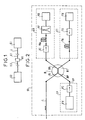
- Figure 1 shows an overview of a optical link according to the present invention.
- Figure 2 shows a view of a station end of the link in Figure 1.
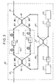
- Figure 3 shows a view of a device line amplification included in the figure link 1.
- line L is a line simple that guides the amplified transmit signal and the signal of reception of the first station in the same fiber optical, this at least in the vicinity of this first station.
- This fiber constitutes a line fiber.
- the line L is simple over its entire length.
- the coupling means of this first station then have a distributor B constituted by a coupler passive twice two having two groups of branches each comprising two branches. Any signal received on one any of these two branches of any of these two groups are transmitted by this coupler, for example at 50% of the strength of this signal, to each of the two branches of the other of these two groups.
- a first group of branches comprises a branch of BL line connected to line fiber L and a branch of BP pump connected to the EP pump assembly.
- the second branch group has a BR receiving branch connected to the RA optical receiving amplifier and a LV transmission branch connected to the optical amplifier TA emission.
- Optical receiving and transmitting amplifiers RA and TA, the EP pump assembly and the coupler B constitute together a station amplification device.
- the RX receiver is sensitive to waves whose wavelength is both the wavelength of reception ⁇ R of the first station and the wavelength of the second station.
- the receiving and transmitting wavelengths can be different from those just mentioned and then be very close to each other, for example 1545 and 1546 nm, are further apart, for example one in the interval 1520-1540 nm, the other in the interval 1540-1560 nm, that is to say very distant for example close to 1300 and 1500 nm.
- Amplifiers and pump wavelengths are of course adapted to the reception wavelengths and emission.
- the reception terminal ER comprises a optical filtering means such as an RF filter or a spectral demultiplexer connected between the amplifier RA reception optics and RX receiver to prevent the receiving pump wave to reach this receiver and reduce the amount of light amplified by this amplifier, in particular amplified spontaneous emission seen by the RX receiver while transmitting the signal amplified reception to this receiver.
- a optical filtering means such as an RF filter or a spectral demultiplexer connected between the amplifier RA reception optics and RX receiver to prevent the receiving pump wave to reach this receiver and reduce the amount of light amplified by this amplifier, in particular amplified spontaneous emission seen by the RX receiver while transmitting the signal amplified reception to this receiver.
- It also includes a RI optical isolator connected between the sharing coupler pump B and the RA receiving optical amplifier for prevent light amplified by this amplifier, including amplified spontaneous emission, to head towards this coupler.
- the transmission terminal ET further comprises a means emission isolation such as a TI optical isolator or a filter connected between TX transmitter and amplifier TA emission to prevent the emission pump wave as well that light amplified by this amplifier, in particular amplified spontaneous emission, reaching the transmitter.
- a means emission isolation such as a TI optical isolator or a filter connected between TX transmitter and amplifier TA emission to prevent the emission pump wave as well that light amplified by this amplifier, in particular amplified spontaneous emission, reaching the transmitter.
- the EP pump assembly includes at least one PX pump such as a laser diode and pump isolation means such as a PI optical isolator or a filter connected between the pump sharing coupler B and the pump PX for prevent amplified transmit signal and signal amplified spontaneous emission reaching the pump.
- PX pump such as a laser diode
- pump isolation means such as a PI optical isolator or a filter connected between the pump sharing coupler B and the pump PX for prevent amplified transmit signal and signal amplified spontaneous emission reaching the pump.
- the bidirectional optical link described above has a resistance comparable to that of bonds known, in particular with regard to three risks which are indicated below in the event that the only devices amplification included in this link are the station amplification devices as described above.
- a first risk is linked to the following facts:
- the amplified emission signal has a strong power in the vicinity of the transmitting station (for example the first station). -The Rayleigh backscatter in the line fiber L is therefore important. Light as well backscattered is partially directed by coupler B to the ER receiver assembly and could therefore prevent the latter to correctly detect the reception signal. But it was found in the context of the present invention that it was easy to give the wavelengths of reception ⁇ R and emission ⁇ T of the values sufficiently different to avoid this inconvenience, for example with using the RF filter, without these wavelengths coming out of the spectral range suitably transmitted by a line L of a usual type nor of the spectral domain suitably amplified by optical amplifiers of the usual type. Of such values have been indicated above.
- a second risk is linked to the following facts: part of the amplifier output power TA transmission signal is returned to this amplifier by Rayleigh backscatter in line fiber L and can therefore be re-amplified at the same time as the signal supplied by TX transmitter and thus alter the signal provided by this amplifier. It was however found, in the context of the present invention, that saturation normally realized from the gain of such a power amplifier was such that this alteration remains negligible.
- a third risk is linked to the following facts:
- a fraction of the strength of the receive signal is directed by coupler B to the optical amplifier TA emission. It is therefore amplified by the latter and could contribute in a variable way to the saturation of the gain of this amplifier. As a result, the signal in this amplifier would be amplified variable i.e. the amplified emission signal would carry parasitic modulation. But, as part of the present invention it has been found that the power of the reception signal received by the optical amplifier emission was in a typical case of a level sufficiently low and in any case much lower than the transmission signal sent by TX so that this drawback potential is negligible.
- the level of modulation parasite in question is typically around 0.5 dB in the case of a received power of -30 dBm.
- a fourth risk is linked to the following facts:
- Line fiber can break between the coupler pump sharing and the optical transmission amplifier of the second station resulting in a reflection of the light.
- the TA emission optical amplifier of the first station then receives its own signal which has been reflected by the breakout and which was delayed by its back and forth propagation in line L.
- the present invention allowed a doubling of the amount of information transmitted by a line without causing practice the additional risks that could be dreaded.
- first and second insulators IA1 and IA2 amplification optics are included in the first and second amplifiers FA1 and FA2 for selectively transmit propagating light waves from the first and second couplers, respectively.
- each such amplifier as FA1 includes two amplifying fibers such as FD1 and FD2 on the one hand and other of the insulator such as IA1, which allows both ensure more efficient pumping because bidirectional and limit the amplification of spontaneous emission contradictory.
- the amplification device in AL line includes first and second PX1 pumps and PX2 with first and second insulators pump protection optics PI1 and PI2, respectively. These two pumps each supply the two pump channels VP1 and VP2 via the same mixing coupler of CP pump in order to make this device resistant to failure of one of these two pumps.
- the line length L between two devices successive amplification is typically of the order of 40 km or more, these devices being located either in station, either online.
Landscapes
- Physics & Mathematics (AREA)
- Electromagnetism (AREA)
- Engineering & Computer Science (AREA)
- Computer Networks & Wireless Communication (AREA)
- Signal Processing (AREA)
- Optical Communication System (AREA)
- Lasers (AREA)
Abstract
Description
- un premier amplificateur optique et un deuxième amplificateur optique constitués de guides transmettant respectivement la première et la deuxième ondes porteuses, ces guides étant dopés pour pouvoir amplifier ces ondes lorsqu'ils sont excités par des ondes de pompe,
- au moins une pompe pour fournir sur une voie de pompe une lumière de pompe apte à constituer lesdites ondes de pompe,
- et des moyens de couplage de pompe raccordant ladite voie de pompe aux deux dits amplificateurs pour leur fournir respectivement les deux dites ondes de pompe à partir de ladite lumière de pompe.
- Un amplificateur optique de réception tel qu'un préamplificateur à fibre optique dopée RA recevant un signal de réception de nature optique transmis à cette station sur la ligne L. Cet amplificateur est pompé optiquement par une onde de pompe de réception de manière à amplifier ce signal de réception.
- Un récepteur RX comportant un photodétecteur tel qu'une diode semiconductrice pour recevoir ce signal de réception amplifié et pour fournir en réponse une information de réception qui était portée par ce signal. L'amplificateur de réception et ce récepteur sont inclus dans un terminal de réception ER.
- Un émetteur TX comprenant une source optique telle qu'un laser semiconducteur recevant une information d'émission à transmettre et fournissant en réponse un signal d'émission de nature optique portant ce signal.
- Un amplificateur optique d'émission tel qu'un postamplificateur à fibre optique dopée TA recevant ce signal d'émission. Cet amplificateur est pompé optiquement par une onde de pompe d'émission de manière à fournir un signal d'émission amplifié. L'émetteur et l'amplificateur d'émission sont inclus dans un terminal d'émission ET.
- Un ensemble de pompe EP fournissant les ondes de pompe de réception et d'émission.
- Des moyens de couplage recevant les ondes de pompe de réception et d'émission et transmettant ces ondes aux amplificateurs optiques de réception et d'émission, respectivement.
- Des moyens de couplage recevant le signal de réception à partir de la ligne L et transmettant ce signal à l'amplificateur de réception RA.
- Enfin des moyens de couplage recevant le signal d'émission à partir de l'ensemble d'émission ET et transmettant ce signal à la ligne L.
- un premier et un deuxième amplificateurs optiques FA1 et FA2 aptes à recevoir une première et une deuxième onde de pompe et à recevoir et à amplifier alors les ondes présentant lesdites première et deuxième longueurs d'onde respectivement,
- au moins une pompe PX1 pour fournir sur une première et une deuxième voies de pompe VP1 et VP2 une lumière de pompe apte à constituer ces ondes de pompe,
- et un premier et un deuxième distributeurs constitués par des coupleurs B1 et B2 dudit type passif deux fois deux. Les branches de ligne BL1 et BL2 de ces deux coupleurs sont raccordées aux premier et deuxième tronçons de ligne L1 et L2, leurs branches de pompe BP1 et BP2 sont raccordées aux première et deuxième voies de pompe VP1 et VP2, leurs branches de réception BR1 et BR2 sont raccordées aux premier et deuxième amplificateurs FA1 et FA2, et leurs branches d'émission BT1 et BT2 sont raccordées aux deuxième et premier amplificateurs FA2 et FA1, respectivement. De préférence chaque tel amplificateur tel que FA1 comporte deux fibres amplificatrices telles que FD1 et FD2 de part et d'autre de l'isolateur tel que IA1, ce qui permet à la fois d'assurer un pompage plus efficace parce que l'amplification de l'émission spontanée contradirectionnelle.
Claims (10)
- Dispositif d'amplification pour liaison optique bidirectionnelle, cette liaison transmettant au moins une première et au moins une deuxième onde porteuse portant des informations et se propageant dans un guide optique respectivement dans une première et une deuxième directions mutuellement opposées, ce dispositif comportant :ce dispositif étant caractérisé par le fait que lesdits moyens de couplage de pompe comportent un distributeur (B) possédant quatre branches constituant :un premier (RA) et un deuxième (TA) amplificateurs optiques constitués de guides transmettant respectivement la première et la deuxième ondes porteuses, ces guides étant dopés pour pouvoir amplifier ces ondes lorsqu'ils sont excités par des ondes de pompe,au moins une pompe (PX) pour fournir sur une voie de pompe (VP) une lumière de pompe apte à constituer lesdites ondes de pompe,et des moyens de couplage de pompe raccordant ladite voie de pompe aux deux dits amplificateurs optiques pour leur fournir respectivement les deux dites ondes de pompe à partir de ladite lumière de pompe,ce distributeur étant apte :une branche de ligne (BL) raccordée à une fibre de ligne (L) guidant les deux dites ondes porteuses.- une branche de pompe (BP) raccordée à ladite voie de pompe (VP), etune première et une deuxième branches d'amplification (BR et BT) respectivement raccordées aux dits premier et deuxième amplificateurs optiques (RA et TA),à transmettre ladite lumière de pompe à partir de la dite branche de pompe partiellement vers chacune de ses deux dites première et deuxième branches d'amplification,à transmettre ladite première onde porteuse à partir de sa dite branche de ligne au moins partiellement à sa dite première branche d'amplification,et à transmettre ladite deuxième onde porteuse à partir de sa dite deuxième branche d'amplification au moins partiellement à sa dite branche de ligne.
- Dispositif selon la revendication 1, ledit distributeur étant constitué par un coupleur optique passif deux fois deux.
- Système de liaison optique bidirectionnelle comportant une première et une deuxième stations (S1 et S2) situées à distance l'une de l'autre et reliées l'une à l'autre par une ligne (L) à fibre optique, chacune de ces deux stations comportant des éléments optiques d'émission et de réception qui sont les suivants au moins dans le cas de ladite première station (S1) :ce système de liaison comportant pour cette station:un amplificateur optique de réception (RA) recevant un signal de réception de nature optique portant une information de réception et transporté à cette station par la ligne (L), cet amplificateur étant pompé optiquement par une onde de pompe de réception de manière à amplifier ce signal de réception,un récepteur (RX) pour recevoir ce signal de réception amplifié et pour fournir en réponse l'information de réception qui était portée par ce signal, l'amplificateur optique de réception et ce récepteur étant inclus dans un terminal de réception (ER),un émetteur (TX) recevant une information d'émission à transmettre et fournissant en réponse un signal d'émission de nature optique portant cette information, etun amplificateur optique d'émission (TA) recevant ce signal d'émission, cet amplificateur étant pompé optiquement par une onde de pompe d'émission de manière à fournir un signal d'émission amplifié, l'émetteur et l'amplificateur d'émission étant inclus dans un terminal d'émission (ET),ce système de liaison étant caractérisé par le fait que la ligne (L) guide le signal d'émission amplifiée et le signal de réception de la première station dans une même fibre optique, cette fibre constituant une fibre de ligne (L),un ensemble de pompe (EP) fournissant une lumière de pompe apte à constituer lesdites ondes de pompe de réception et d'émission, etun ensemble de couplage, cet ensemble de couplage constituant :des moyens de couplage recevant la lumière de pompe et dirigeant cette lumière vers les amplificateurs optiques de réception et d'émission, les amplificateurs optiques de réception (RA) et d'émission (TA) et l'ensemble de pompe (EP) constituant avec ces moyens de couplage un dispositif d'amplification de station,des moyens de couplage recevant le signal de réception à partir de la ligne (L) et transmettant ce signal à l'amplificateur de réception,et des moyens de couplage recevant le signal d'émission à partir de l'ensemble d'émission et transmettant ce signal à la ligne (L),
ledit ensemble de couplage pour cette première station comportant un distributeur (B) à deux groupes de deux branches, les deux branches d'un groupe (BL et BP) étant respectivement raccordées à une fibre de ligne (L) guidant les deux ondes porteuses et à la voie de pompe (VP), les deux branches de l'autre groupe (BR et BT) étant respectivement raccordées aux deux dits amplificateurs optiques (RA) et (TA) pour coupler la fibre de ligne et la voie de pompe à ces deux amplificateurs, ledit récepteur (RX) de la première station étant sensible à des ondes présentant une première longueur d'onde constituant à la fois la longueur d'onde de réception (lR) de la première station et une longueur d'onde d'émission de la deuxième station, l'émetteur (TX) de la première station émettant à une deuxième longueur d'onde (lT) qui constitue à la fois la longueur d'onde d'émission de la première station et la longueur d'onde de réception de la deuxième station et qui est différente de la première longueur d'onde. - Système de liaison selon la revendication 3, ledit distributeur (B) étant constitué par un coupleur optique passif deux fois deux ayant deux groupes de branches comportant chacun deux branches et tel que tout signal reçu sur l'une quelconque de ces deux branches de l'un quelconque de ces deux groupes soit transmis en partie par ce coupleur à chacune des deux branches de l'autre de ces deux groupes,
un groupe de branches comportant une branche de ligne (BL) raccordée à la fibre de ligne (L) et une branche de pompe (BP) raccordée à l'ensemble de pompe (EP), l'autre groupe de branches comportant une branche de réception (BR) raccordée à l'amplificateur optique de réception (RA) et une branche d'émission (BT) raccordée à l'amplificateur optique d'émission (TA). - Système de liaison selon la revendication 3, caractérisé par le fait que le terminal de réception (ER) comporte un moyen de filtrage (RF) raccordé entre l'amplificateur optique de réception (RA) et le récepteur (RX) et transmettant sélectivement le signal de réception amplifié à ce récepteur.
- Système de liaison selon la revendication 3, caractérisé par le fait que le terminal de réception (ER) comporte en outre un isolateur optique (RI) raccordé entre l'élément de partage de pompe (B) et l'amplificateur optique de réception (RA) pour empêcher une lumière amplifiée par cet amplificateur de se diriger vers ce coupleur.
- Système de liaison selon la revendication 3, caractérisé par le fait que le terminal d'émission (ET) comporte en outre un moyen d'isolation d'émission (TI) raccordé entre l'émetteur (TX) et l'amplificateur optique d'émission (TA) pour empêcher des ondes lumineuses d'atteindre l'émetteur.
- Système de liaison selon la revendication 3, caractérisé par le fait que l'ensemble de pompe (EP) comporte au moins une pompe (PX) et un moyen d'isolation de pompe (PI) raccordé entre l'élément de partage de pompe (B) et chaque pompe (PX) pour empêcher le signal d'émission amplifié d'atteindre cette pompe.
- Système de liaison optique bidirectionnelle comportant une première et une deuxième stations (S1, S2) reliées l'une à l'autre par une fibre de ligne (L) pour transmettre une première et une deuxième ondes porteuses portant des informations et se propageant dans ladite fibre de ligne respectivement dans une première direction et dans une deuxième direction opposée à cette première direction, ce système de liaison comportant en outre au moins un dispositif d'amplification en ligne (AL) inséré entre un premier et un deuxième tronçons successifs (L1 et L2) appartenant à ladite fibre de ligne (L) et situés des côtés desdites première et deuxième stations (S1 et S2), respectivement, ce dispositif comportant :un premier et un deuxième amplificateurs optiques (FA1 et FA2) aptes à recevoir une première et une deuxième ondes de pompe et à recevoir et à amplifier alors les ondes, au moins, lesdites première et deuxième ondes porteuses, respectivement, etun ensemble de pompe (PX1) pour fournir sur une première et une deuxième voies de pompe (VP1 et VP2) une lumière de pompe apte à constituer lesdites ondes de pompe,ledit système de liaison étant caractérisé par le fait que ledit dispositif d'amplification comporte un premier et un deuxième distributeurs (B1, B2) à deux groupes de deux branches avec couplage des branches de chaque dit groupe de branches de chaque distributeur aux branches de l'autre dit groupe de branches de ce distributeur, un groupe de branches de chaque distributeur étant constitué par une branche de ligne et une branche de pompe, l'autre groupe de branches de chaque distributeur étant constitué par une branche de réception et une branche d'émission, lesdites branches de ligne (BL1 et BL2) de ces deux distributeurs étant raccordées auxdits premier et deuxième tronçons de ligne (L1 et L2), lesdites branches de pompe (BP1 et BP2) de ces deux distributeurs étant raccordées auxdites première et deuxième voies de pompe (VP1 et VP2), lesdites branches de réception (BR1 et BR2) de ces deux distributeurs étant raccordées auxdits premier et deuxième amplificateurs optiques (FA1 et FA2), lesdites branches d'émission (BT1 et BT2) de ces deux distributeurs étant raccordées auxdits deuxième et premier amplificateurs optiques (FA2 et FA1), respectivement.
- Système de liaison selon la revendication 9, caractérisé par le fait que ledit ensemble de pompe comporte une première et une deuxième pompes (PX1 et PX2) munies d'un premier et d'un deuxième isolateurs optiques de protection de pompe (PI1 et PI2), respectivement, et alimentant chacune les deux dites voies de pompe (VP1 et VP2) par l'intermédiaire d'un même coupleur de mélange de pompe (CP) de manière à rendre ce dispositif résistant à la défaillance d'une de ces deux pompes.
Applications Claiming Priority (3)
| Application Number | Priority Date | Filing Date | Title |
|---|---|---|---|
| FR9601406 | 1996-02-06 | ||
| FR9601406A FR2744579B1 (fr) | 1996-02-06 | 1996-02-06 | Liaison optique bidirectionnelle et dispositif d'amplification pour cette liaison |
| PCT/FR1997/000204 WO1997029562A1 (fr) | 1996-02-06 | 1997-02-03 | Liaison optique bidirectionnelle et dispositif d'amplification pour cette liaison |
Publications (2)
| Publication Number | Publication Date |
|---|---|
| EP0879509A1 EP0879509A1 (fr) | 1998-11-25 |
| EP0879509B1 true EP0879509B1 (fr) | 2001-04-11 |
Family
ID=9488877
Family Applications (1)
| Application Number | Title | Priority Date | Filing Date |
|---|---|---|---|
| EP97902428A Expired - Lifetime EP0879509B1 (fr) | 1996-02-06 | 1997-02-03 | Liaison optique bidirectionnelle et dispositif d'amplification pour cette liaison |
Country Status (6)
| Country | Link |
|---|---|
| US (1) | US6023543A (fr) |
| EP (1) | EP0879509B1 (fr) |
| AU (1) | AU1607597A (fr) |
| DE (1) | DE69704550T2 (fr) |
| FR (1) | FR2744579B1 (fr) |
| WO (1) | WO1997029562A1 (fr) |
Families Citing this family (3)
| Publication number | Priority date | Publication date | Assignee | Title |
|---|---|---|---|---|
| US6091869A (en) * | 1998-04-30 | 2000-07-18 | Telefonaktiebolaget Lm Ericsson | Low loss, optical add/drop WDM node |
| US6532321B1 (en) * | 2000-02-16 | 2003-03-11 | Adc Telecommunications, Inc. | Fiber optic isolator for use with multiple-wavelength optical signals |
| GB2361597A (en) * | 2000-04-20 | 2001-10-24 | Abb Offshore Systems Ltd | Underwater optical fibre communication system |
Family Cites Families (4)
| Publication number | Priority date | Publication date | Assignee | Title |
|---|---|---|---|---|
| DE69224340T2 (de) * | 1991-09-30 | 1998-06-04 | Nippon Electric Co | Zweiwegzwischenverstärker mit optischer Verstärkung |
| US5241414A (en) * | 1992-08-21 | 1993-08-31 | At&T Bell Laboratories | Fault tolerant optical amplifier arrangement |
| WO1995015625A1 (fr) * | 1993-12-01 | 1995-06-08 | Williams Telecommunications Group, Inc. | Amplificateur optique bidirectionnel |
| US5898801A (en) * | 1998-01-29 | 1999-04-27 | Lockheed Martin Corporation | Optical transport system |
-
1996
- 1996-02-06 FR FR9601406A patent/FR2744579B1/fr not_active Expired - Fee Related
-
1997
- 1997-02-03 DE DE69704550T patent/DE69704550T2/de not_active Expired - Fee Related
- 1997-02-03 AU AU16075/97A patent/AU1607597A/en not_active Abandoned
- 1997-02-03 WO PCT/FR1997/000204 patent/WO1997029562A1/fr not_active Ceased
- 1997-02-03 US US09/117,735 patent/US6023543A/en not_active Expired - Fee Related
- 1997-02-03 EP EP97902428A patent/EP0879509B1/fr not_active Expired - Lifetime
Also Published As
| Publication number | Publication date |
|---|---|
| DE69704550T2 (de) | 2002-04-11 |
| FR2744579A1 (fr) | 1997-08-08 |
| US6023543A (en) | 2000-02-08 |
| DE69704550D1 (de) | 2001-05-17 |
| AU1607597A (en) | 1997-08-28 |
| WO1997029562A1 (fr) | 1997-08-14 |
| EP0879509A1 (fr) | 1998-11-25 |
| FR2744579B1 (fr) | 1998-02-27 |
Similar Documents
| Publication | Publication Date | Title |
|---|---|---|
| US6173094B1 (en) | Optical-transmission system having a split-gain amplifier and a signal-modifying device | |
| FR2827455A1 (fr) | Systeme de transmission optique, station terminale et repeteur | |
| FR2756994A1 (fr) | Egaliseur optique | |
| FR2765752A1 (fr) | Amplificateur a fibre optique pour atteindre un gain eleve d'un petit signal | |
| FR2820550A1 (fr) | Amplificateur de raman et systeme de transmission optique utilisant l'amplificateur | |
| FR2775856A1 (fr) | Systeme et terminal de multiplexage en longueur d'onde optique | |
| EP0802645B1 (fr) | Amplificateur optique à gain variable et à bande passante constante, et système de compensation automatique des variations des pertes dans une liaison optique, comportant un tel amplificateur | |
| EP0802641A1 (fr) | Montage à deux amplificateurs optiques, notamment pour répéteur d'un système de télécommunications par voie sous-marine | |
| EP2050213B1 (fr) | Reseau optique passif longue distance utilisant la modulation deportee d'un signal optique d'amplification | |
| FR2796766A1 (fr) | Amplificateur optique a pompage bidirectionnel | |
| FR2744866A1 (fr) | Installation de transmission de signaux par voie optique comprenant un systeme de surveillance des repeteurs | |
| WO1997029562A1 (fr) | Liaison optique bidirectionnelle et dispositif d'amplification pour cette liaison | |
| JP3129368B2 (ja) | 光信号伝送方法および中継増幅器 | |
| FR2756993A1 (fr) | Systeme de transmission a amplification/repetition optique et amplificateur optique | |
| EP0975106B1 (fr) | Dispositif de régénération en ligne d'un signal optique de solitons par une modulation synchrone de ces solitons et système de transmission comportant un tel dispositif | |
| EP1067640A1 (fr) | Systèmes de communication par fibre optique utilisant l'amplification Raman | |
| EP1130701A1 (fr) | Amplificateur optique à fibre à gaine multimode en bande C | |
| FR2696302A1 (fr) | Liaison à fibres optiques et amplificateur pour cette liaison. | |
| EP2163011B1 (fr) | Reseau optique longue distance avec localisation des moyens d'amplification au niveau du central optique | |
| EP1059710A1 (fr) | Amplificateur raman hybride | |
| EP1067641A1 (fr) | Amplificateur Raman avec système de pompage déporté | |
| EP1274185B1 (fr) | Système de transmission optique avec amplification par diffusion Raman stimulée et égalisation de gain | |
| KR100252178B1 (ko) | 광 아이솔레이터 복합모듈 및 이를 사용한 광 증폭기 | |
| EP0530108A1 (fr) | Dispositif séparateur-mélangeur de fréquences pour ondes optiques guidées | |
| FR2787953A1 (fr) | Amplification quasi-distribuee dans un systeme de transmission a fibre optique |
Legal Events
| Date | Code | Title | Description |
|---|---|---|---|
| PUAI | Public reference made under article 153(3) epc to a published international application that has entered the european phase |
Free format text: ORIGINAL CODE: 0009012 |
|
| 17P | Request for examination filed |
Effective date: 19980907 |
|
| AK | Designated contracting states |
Kind code of ref document: A1 Designated state(s): DE ES FR GB IT SE |
|
| GRAG | Despatch of communication of intention to grant |
Free format text: ORIGINAL CODE: EPIDOS AGRA |
|
| 17Q | First examination report despatched |
Effective date: 20000711 |
|
| GRAG | Despatch of communication of intention to grant |
Free format text: ORIGINAL CODE: EPIDOS AGRA |
|
| GRAH | Despatch of communication of intention to grant a patent |
Free format text: ORIGINAL CODE: EPIDOS IGRA |
|
| GRAH | Despatch of communication of intention to grant a patent |
Free format text: ORIGINAL CODE: EPIDOS IGRA |
|
| GRAA | (expected) grant |
Free format text: ORIGINAL CODE: 0009210 |
|
| RAP1 | Party data changed (applicant data changed or rights of an application transferred) |
Owner name: ALCATEL |
|
| AK | Designated contracting states |
Kind code of ref document: B1 Designated state(s): DE ES FR GB IT SE |
|
| GBT | Gb: translation of ep patent filed (gb section 77(6)(a)/1977) |
Effective date: 20010411 |
|
| REF | Corresponds to: |
Ref document number: 69704550 Country of ref document: DE Date of ref document: 20010517 |
|
| ITF | It: translation for a ep patent filed | ||
| PG25 | Lapsed in a contracting state [announced via postgrant information from national office to epo] |
Ref country code: ES Free format text: LAPSE BECAUSE OF FAILURE TO SUBMIT A TRANSLATION OF THE DESCRIPTION OR TO PAY THE FEE WITHIN THE PRESCRIBED TIME-LIMIT Effective date: 20011030 |
|
| REG | Reference to a national code |
Ref country code: GB Ref legal event code: IF02 |
|
| PLBE | No opposition filed within time limit |
Free format text: ORIGINAL CODE: 0009261 |
|
| STAA | Information on the status of an ep patent application or granted ep patent |
Free format text: STATUS: NO OPPOSITION FILED WITHIN TIME LIMIT |
|
| 26N | No opposition filed | ||
| PGFP | Annual fee paid to national office [announced via postgrant information from national office to epo] |
Ref country code: IT Payment date: 20060228 Year of fee payment: 10 |
|
| PGFP | Annual fee paid to national office [announced via postgrant information from national office to epo] |
Ref country code: SE Payment date: 20070213 Year of fee payment: 11 |
|
| PGFP | Annual fee paid to national office [announced via postgrant information from national office to epo] |
Ref country code: GB Payment date: 20070216 Year of fee payment: 11 Ref country code: DE Payment date: 20070216 Year of fee payment: 11 |
|
| REG | Reference to a national code |
Ref country code: FR Ref legal event code: CD |
|
| PGFP | Annual fee paid to national office [announced via postgrant information from national office to epo] |
Ref country code: FR Payment date: 20070212 Year of fee payment: 11 |
|
| EUG | Se: european patent has lapsed | ||
| GBPC | Gb: european patent ceased through non-payment of renewal fee |
Effective date: 20080203 |
|
| REG | Reference to a national code |
Ref country code: FR Ref legal event code: ST Effective date: 20081031 |
|
| PG25 | Lapsed in a contracting state [announced via postgrant information from national office to epo] |
Ref country code: SE Free format text: LAPSE BECAUSE OF NON-PAYMENT OF DUE FEES Effective date: 20080204 Ref country code: DE Free format text: LAPSE BECAUSE OF NON-PAYMENT OF DUE FEES Effective date: 20080902 |
|
| PG25 | Lapsed in a contracting state [announced via postgrant information from national office to epo] |
Ref country code: FR Free format text: LAPSE BECAUSE OF NON-PAYMENT OF DUE FEES Effective date: 20080229 |
|
| PG25 | Lapsed in a contracting state [announced via postgrant information from national office to epo] |
Ref country code: GB Free format text: LAPSE BECAUSE OF NON-PAYMENT OF DUE FEES Effective date: 20080203 |
|
| PG25 | Lapsed in a contracting state [announced via postgrant information from national office to epo] |
Ref country code: IT Free format text: LAPSE BECAUSE OF NON-PAYMENT OF DUE FEES Effective date: 20070203 |