EP0879573A1 - Befestigungselement für eine Profilschiene - Google Patents
Befestigungselement für eine Profilschiene Download PDFInfo
- Publication number
- EP0879573A1 EP0879573A1 EP98105492A EP98105492A EP0879573A1 EP 0879573 A1 EP0879573 A1 EP 0879573A1 EP 98105492 A EP98105492 A EP 98105492A EP 98105492 A EP98105492 A EP 98105492A EP 0879573 A1 EP0879573 A1 EP 0879573A1
- Authority
- EP
- European Patent Office
- Prior art keywords
- rail
- narrow side
- fastening element
- fastener
- ceiling
- Prior art date
- Legal status (The legal status is an assumption and is not a legal conclusion. Google has not performed a legal analysis and makes no representation as to the accuracy of the status listed.)
- Granted
Links
- 239000002184 metal Substances 0.000 title 1
- 229910000639 Spring steel Inorganic materials 0.000 claims description 3
- 229910000831 Steel Inorganic materials 0.000 abstract 1
- 239000010959 steel Substances 0.000 abstract 1
- 239000012858 resilient material Substances 0.000 description 1
Images
Classifications
-
- F—MECHANICAL ENGINEERING; LIGHTING; HEATING; WEAPONS; BLASTING
- F16—ENGINEERING ELEMENTS AND UNITS; GENERAL MEASURES FOR PRODUCING AND MAINTAINING EFFECTIVE FUNCTIONING OF MACHINES OR INSTALLATIONS; THERMAL INSULATION IN GENERAL
- F16B—DEVICES FOR FASTENING OR SECURING CONSTRUCTIONAL ELEMENTS OR MACHINE PARTS TOGETHER, e.g. NAILS, BOLTS, CIRCLIPS, CLAMPS, CLIPS OR WEDGES; JOINTS OR JOINTING
- F16B2/00—Friction-grip releasable fastenings
- F16B2/20—Clips, i.e. with gripping action effected solely by the inherent resistance to deformation of the material of the fastening
- F16B2/22—Clips, i.e. with gripping action effected solely by the inherent resistance to deformation of the material of the fastening of resilient material, e.g. rubbery material
- F16B2/24—Clips, i.e. with gripping action effected solely by the inherent resistance to deformation of the material of the fastening of resilient material, e.g. rubbery material of metal
- F16B2/241—Clips, i.e. with gripping action effected solely by the inherent resistance to deformation of the material of the fastening of resilient material, e.g. rubbery material of metal of sheet metal
Definitions
- the invention relates to a fastening element for a profile rail in the form of a resilient elastic clip.
- Profile rails especially curtain rails, are today in usually screwed directly to a ceiling or wall. Since the Rail pieces are usually very long and during screwing must be pressed against the ceiling or wall the assembly of such rails has been relatively cumbersome. Often it can only be carried out with the help of a second person.
- the present invention proposes a fastener for a profile rail in the form of a resilient elastic bracket in front of at least one narrow side encloses the rail and on a wall or ceiling can be fastened, with one end of the clip in an undercut Opening or groove on the top of the rail insertable and the second end over the lower edge of the narrow side of the rail is clipable.
- the fasteners according to the invention can be pre-assembled, which is not a problem represents and also be carried out by one person alone can. Then the one ends of the fasteners into the openings or grooves on the top of the Rail inserted and then by pressing the rail second ends of the fasteners over the lower edge of the Clipped narrow side of the rails.
- Fastening clips are thus the mounting of profile rails without effort and also by one person alone feasible.
- the fasteners can expediently Can be attached to a wall or ceiling using screws be.
- At least the narrow side of the rail overlapping part of the fastener a groove-like Have recess for receiving a screw head, so that this does not interfere with the assembly of the rail.
- the above the lower edge of the narrow side clipable end of the fastener can also be turned down to one Redoing the connection between the fastener and Allow rail if the rail is removed again shall be.
- the fastening element can expediently be bent from spring steel. But also the use other resilient materials are possible.
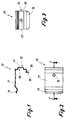
- the fastener 10 shown in FIGS. 1 to 3 is a clip made of spring steel with an upper part 11, that on the top of a rail, not shown rests, and a side part 12 which is parallel to a Narrow side of a profile rail runs.
- the free end 13 the upper part 11 is bent in a scoop-shaped manner and can be from above into an undercut opening or groove Profile rail are introduced.
- the second end 14 of the fastener 10 is bent twice and at right angles encloses the lower edge of the narrow side of the profile rail and then projects vertically downward around a tab 15 to form, on which the fastener 10 again from the Profile rail is to be loosened.
- the fastener 10 has 12 holes in both its upper part 11 and in the side part 16, 17 for mounting screws so that it is both on a ceiling and can be attached to a wall.
- the hole 17 is in a groove-shaped recess 18 in the side part 12 arranged in the head of a screw completely can be sunk.
- the dimensions of the fastening clip 10 are preferably such on the rail to be attached matched that it is clamping the narrow side of the rail encloses. After mounting the fastener 10 on the wall or ceiling will end 13 into the top undercut groove or opening of the rail inserted and then the second end 14 by pressing the rail clipped over the lower edge of the narrow side of the profile rail.
Landscapes
- Engineering & Computer Science (AREA)
- General Engineering & Computer Science (AREA)
- Mechanical Engineering (AREA)
- Clamps And Clips (AREA)
- Joining Of Building Structures In Genera (AREA)
- Railway Tracks (AREA)
- Connection Of Plates (AREA)
- Curtains And Furnishings For Windows Or Doors (AREA)
Abstract
Description
- Fig. 1
- einen zentralen Längsschnitt durch ein Befestigungselement entlang der Linie I - I in Fig. 2;
- Fig. 2
- eine Ansicht von oben auf das Befestigungselement in Fig. 1;
- Fig. 3
- eine Seitenansicht auf das Befestigungselement aus Fig. 1.
Claims (5)
- Befestigungselement für eine Profilschiene in Form einer federnd elastischen Klammer, die mindestens eine Schmalseite der Schiene umschließt und an einer Wand oder Decke befestigbar ist, wobei ein Ende (13) der Klammer in eine hinterschnittene Öffnung oder Nut auf der Oberseite der Schiene einführbar und das zweite Ende (14) über die Unterkante der Schienenschmalseite clipsbar ist.
- Befestigungselement nach Anspruch 1, dadurch gekennzeichnet, daß es mittels Schrauben an einer Wand oder Decke befestigbar ist.
- Befestigungselement nach Anspruch 2, dadurch gekennzeichnet, daß mindestens der die Schmalseite der Schiene umschließende Teil (12) des Befestigungselementes (10) eine nutartige Vertiefung (18) zur Aufnahme eines Schraubenkopfes aufweist.
- Befestigungselement nach einem der Ansprüche 1 bis 3, dadurch gekennzeichnet, daß das über die Unterseite der Schmalseite der Schiene clipsbare Ende (14) nach unten abgebogen ist, um ein Losen der Verbindung zwischen Befestigungselement (10) und Schiene zu ermöglichen.
- Befestigungselement nach einem der Ansprüche 1 bis 4, dadurch gekennzeichnet, daß es aus Federstahl gebogen ist.
Applications Claiming Priority (2)
| Application Number | Priority Date | Filing Date | Title |
|---|---|---|---|
| DE29709086U DE29709086U1 (de) | 1997-05-23 | 1997-05-23 | Befestigungselement für eine Profilschiene |
| DE29709086U | 1997-05-23 |
Publications (2)
| Publication Number | Publication Date |
|---|---|
| EP0879573A1 true EP0879573A1 (de) | 1998-11-25 |
| EP0879573B1 EP0879573B1 (de) | 2002-02-27 |
Family
ID=8040687
Family Applications (1)
| Application Number | Title | Priority Date | Filing Date |
|---|---|---|---|
| EP98105492A Expired - Lifetime EP0879573B1 (de) | 1997-05-23 | 1998-03-26 | Befestigungselement für eine Profilschiene |
Country Status (3)
| Country | Link |
|---|---|
| EP (1) | EP0879573B1 (de) |
| AT (1) | ATE213598T1 (de) |
| DE (2) | DE29709086U1 (de) |
Families Citing this family (1)
| Publication number | Priority date | Publication date | Assignee | Title |
|---|---|---|---|---|
| DE102004008088B4 (de) * | 2004-02-19 | 2007-10-11 | Ikm Industriebedarf Kiparski & Michel Gmbh | Befestigungselement zur Halterung von Leuchten |
Citations (4)
| Publication number | Priority date | Publication date | Assignee | Title |
|---|---|---|---|---|
| US3927437A (en) * | 1974-02-14 | 1975-12-23 | Kirsch Co | Positively supported cam for engaging a traverse rod |
| US4179091A (en) * | 1977-06-06 | 1979-12-18 | Roger Bidney | Vertically adjustable drapery rod support |
| FR2481097A1 (fr) * | 1980-04-28 | 1981-10-30 | Flageollet Michel | Nouveau profil de tringle a rideaux |
| US5060710A (en) * | 1990-06-12 | 1991-10-29 | Cooper Industries, Inc. | Cam bracket and headrail system |
-
1997
- 1997-05-23 DE DE29709086U patent/DE29709086U1/de not_active Expired - Lifetime
-
1998
- 1998-03-26 DE DE59803166T patent/DE59803166D1/de not_active Expired - Lifetime
- 1998-03-26 EP EP98105492A patent/EP0879573B1/de not_active Expired - Lifetime
- 1998-03-26 AT AT98105492T patent/ATE213598T1/de not_active IP Right Cessation
Patent Citations (4)
| Publication number | Priority date | Publication date | Assignee | Title |
|---|---|---|---|---|
| US3927437A (en) * | 1974-02-14 | 1975-12-23 | Kirsch Co | Positively supported cam for engaging a traverse rod |
| US4179091A (en) * | 1977-06-06 | 1979-12-18 | Roger Bidney | Vertically adjustable drapery rod support |
| FR2481097A1 (fr) * | 1980-04-28 | 1981-10-30 | Flageollet Michel | Nouveau profil de tringle a rideaux |
| US5060710A (en) * | 1990-06-12 | 1991-10-29 | Cooper Industries, Inc. | Cam bracket and headrail system |
Also Published As
| Publication number | Publication date |
|---|---|
| DE59803166D1 (de) | 2002-04-04 |
| ATE213598T1 (de) | 2002-03-15 |
| EP0879573B1 (de) | 2002-02-27 |
| DE29709086U1 (de) | 1997-07-17 |
Similar Documents
| Publication | Publication Date | Title |
|---|---|---|
| DE3713283C2 (de) | ||
| EP1168949A1 (de) | Befestigungselement mit variablem hub | |
| EP0879573B1 (de) | Befestigungselement für eine Profilschiene | |
| EP0441363B1 (de) | Einbaugerät mit Abdeckleiste | |
| EP0149773B1 (de) | Befestigungsvorrichtung für Führungsschienen von Aufzügen | |
| AT403242B (de) | Befestigung für eine duschkabine an einer wand | |
| DE8625363U1 (de) | Sicherungselement mit unverlierbaren Schrauben | |
| DE8717745U1 (de) | Vorrichtung zur einstellbaren Befestigung eines Scharnierbandes (Tür, Fenster) an einer Stahlzarge | |
| DE4434018A1 (de) | Verbindung zweier Bauteile mittels einer Kopfschraube und einer Unterlegscheibe | |
| DE806783C (de) | Kappschuh | |
| EP0718549B1 (de) | Befestigungsvorrichtung | |
| DE19504247A1 (de) | Befestigungsanordnung | |
| EP0898658B1 (de) | Befestigungselement für den einsatz in hinterschnittene profilnuten | |
| AT348890B (de) | Schraubverbindung zum befestigen eines beschlaegeteiles in einem ein etwa u-foermiges profil aufweisenden rahmen | |
| DE3726405A1 (de) | Grund- oder befestigungsplatte mit teilweise eingeschraubter befestigungsschraube fuer zu befestigende teile | |
| DE19829708C1 (de) | Vorrichtung zur Befestigung eines Blechaufsatzes für Küchenarbeitsmöbel an einem Unterbau | |
| DE19524648A1 (de) | U-förmige Aufklipsgleitmutter | |
| DE3510675A1 (de) | Halterung fuer schrauben in latten | |
| EP0379656A1 (de) | Verankerungsvorrichtung für Fenster- und Türrahmen | |
| DE3306634A1 (de) | Vorrichtung zum befestigen von montageschienen fuer heizkoerper o. dgl. | |
| DE2537230A1 (de) | Verbindung eines anschlussprofils mit einem rahmenprofil | |
| DE19704375A1 (de) | Badezimmer-Halter | |
| EP0987448A1 (de) | Anordnung zur Befestigung einer Baugruppe mit mindestens einer an dieser Baugruppe vormontierten Befestigungsschraube an einem Träger mit einer zugeordneten Öffnung | |
| DE9212476U1 (de) | Befestigungsvorrichtung für eine Stufe, insbesondere Holzstufe auf einem aus einem anderen Material, insbesondere Beton, bestehenden Untergrund | |
| DE19626709A1 (de) | Befestigungsanordnung |
Legal Events
| Date | Code | Title | Description |
|---|---|---|---|
| PUAI | Public reference made under article 153(3) epc to a published international application that has entered the european phase |
Free format text: ORIGINAL CODE: 0009012 |
|
| AK | Designated contracting states |
Kind code of ref document: A1 Designated state(s): AT BE CH DE FR LI LU NL |
|
| AX | Request for extension of the european patent |
Free format text: AL;LT;LV;MK;RO;SI |
|
| 17P | Request for examination filed |
Effective date: 19990520 |
|
| AKX | Designation fees paid |
Free format text: AT BE CH DE FR LI LU NL |
|
| GRAG | Despatch of communication of intention to grant |
Free format text: ORIGINAL CODE: EPIDOS AGRA |
|
| GRAG | Despatch of communication of intention to grant |
Free format text: ORIGINAL CODE: EPIDOS AGRA |
|
| GRAH | Despatch of communication of intention to grant a patent |
Free format text: ORIGINAL CODE: EPIDOS IGRA |
|
| 17Q | First examination report despatched |
Effective date: 20010704 |
|
| GRAH | Despatch of communication of intention to grant a patent |
Free format text: ORIGINAL CODE: EPIDOS IGRA |
|
| GRAA | (expected) grant |
Free format text: ORIGINAL CODE: 0009210 |
|
| AK | Designated contracting states |
Kind code of ref document: B1 Designated state(s): AT BE CH DE FR LI LU NL |
|
| REF | Corresponds to: |
Ref document number: 213598 Country of ref document: AT Date of ref document: 20020315 Kind code of ref document: T |
|
| REG | Reference to a national code |
Ref country code: CH Ref legal event code: EP |
|
| REG | Reference to a national code |
Ref country code: CH Ref legal event code: NV Representative=s name: ROTTMANN, ZIMMERMANN + PARTNER AG |
|
| PG25 | Lapsed in a contracting state [announced via postgrant information from national office to epo] |
Ref country code: LU Free format text: LAPSE BECAUSE OF NON-PAYMENT OF DUE FEES Effective date: 20020326 |
|
| REF | Corresponds to: |
Ref document number: 59803166 Country of ref document: DE Date of ref document: 20020404 |
|
| ET | Fr: translation filed | ||
| PLBE | No opposition filed within time limit |
Free format text: ORIGINAL CODE: 0009261 |
|
| STAA | Information on the status of an ep patent application or granted ep patent |
Free format text: STATUS: NO OPPOSITION FILED WITHIN TIME LIMIT |
|
| 26N | No opposition filed |
Effective date: 20021128 |
|
| PGFP | Annual fee paid to national office [announced via postgrant information from national office to epo] |
Ref country code: BE Payment date: 20060120 Year of fee payment: 9 |
|
| PGFP | Annual fee paid to national office [announced via postgrant information from national office to epo] |
Ref country code: CH Payment date: 20060123 Year of fee payment: 9 |
|
| PGFP | Annual fee paid to national office [announced via postgrant information from national office to epo] |
Ref country code: FR Payment date: 20060221 Year of fee payment: 9 |
|
| PGFP | Annual fee paid to national office [announced via postgrant information from national office to epo] |
Ref country code: NL Payment date: 20060328 Year of fee payment: 9 |
|
| PGFP | Annual fee paid to national office [announced via postgrant information from national office to epo] |
Ref country code: AT Payment date: 20060329 Year of fee payment: 9 |
|
| REG | Reference to a national code |
Ref country code: CH Ref legal event code: PL |
|
| PG25 | Lapsed in a contracting state [announced via postgrant information from national office to epo] |
Ref country code: AT Free format text: LAPSE BECAUSE OF NON-PAYMENT OF DUE FEES Effective date: 20070326 |
|
| NLV4 | Nl: lapsed or anulled due to non-payment of the annual fee |
Effective date: 20071001 |
|
| BERE | Be: lapsed |
Owner name: *MHZ HACHTEL G.M.B.H. & CO. K.G. Effective date: 20070331 |
|
| PG25 | Lapsed in a contracting state [announced via postgrant information from national office to epo] |
Ref country code: BE Free format text: LAPSE BECAUSE OF NON-PAYMENT OF DUE FEES Effective date: 20070331 |
|
| REG | Reference to a national code |
Ref country code: FR Ref legal event code: ST Effective date: 20071130 |
|
| PG25 | Lapsed in a contracting state [announced via postgrant information from national office to epo] |
Ref country code: NL Free format text: LAPSE BECAUSE OF NON-PAYMENT OF DUE FEES Effective date: 20071001 |
|
| PG25 | Lapsed in a contracting state [announced via postgrant information from national office to epo] |
Ref country code: CH Free format text: LAPSE BECAUSE OF NON-PAYMENT OF DUE FEES Effective date: 20070331 Ref country code: LI Free format text: LAPSE BECAUSE OF NON-PAYMENT OF DUE FEES Effective date: 20070331 |
|
| PG25 | Lapsed in a contracting state [announced via postgrant information from national office to epo] |
Ref country code: FR Free format text: LAPSE BECAUSE OF NON-PAYMENT OF DUE FEES Effective date: 20070402 |
|
| PGFP | Annual fee paid to national office [announced via postgrant information from national office to epo] |
Ref country code: DE Payment date: 20130328 Year of fee payment: 16 |
|
| REG | Reference to a national code |
Ref country code: DE Ref legal event code: R119 Ref document number: 59803166 Country of ref document: DE |
|
| REG | Reference to a national code |
Ref country code: DE Ref legal event code: R119 Ref document number: 59803166 Country of ref document: DE Effective date: 20141001 |
|
| PG25 | Lapsed in a contracting state [announced via postgrant information from national office to epo] |
Ref country code: DE Free format text: LAPSE BECAUSE OF NON-PAYMENT OF DUE FEES Effective date: 20141001 |