EP0879581A2 - Vorrichtung zum Absaugen von Flüssigkeiten - Google Patents
Vorrichtung zum Absaugen von Flüssigkeiten Download PDFInfo
- Publication number
- EP0879581A2 EP0879581A2 EP98109179A EP98109179A EP0879581A2 EP 0879581 A2 EP0879581 A2 EP 0879581A2 EP 98109179 A EP98109179 A EP 98109179A EP 98109179 A EP98109179 A EP 98109179A EP 0879581 A2 EP0879581 A2 EP 0879581A2
- Authority
- EP
- European Patent Office
- Prior art keywords
- suction
- suction element
- support
- oral cavity
- support element
- Prior art date
- Legal status (The legal status is an assumption and is not a legal conclusion. Google has not performed a legal analysis and makes no representation as to the accuracy of the status listed.)
- Withdrawn
Links
Images


Classifications
-
- A—HUMAN NECESSITIES
- A61—MEDICAL OR VETERINARY SCIENCE; HYGIENE
- A61C—DENTISTRY; APPARATUS OR METHODS FOR ORAL OR DENTAL HYGIENE
- A61C17/00—Devices for cleaning, polishing, rinsing or drying teeth, teeth cavities or prostheses; Saliva removers; Dental appliances for receiving spittle
- A61C17/06—Saliva removers; Accessories therefor
- A61C17/08—Aspiration nozzles
-
- A—HUMAN NECESSITIES
- A61—MEDICAL OR VETERINARY SCIENCE; HYGIENE
- A61C—DENTISTRY; APPARATUS OR METHODS FOR ORAL OR DENTAL HYGIENE
- A61C17/00—Devices for cleaning, polishing, rinsing or drying teeth, teeth cavities or prostheses; Saliva removers; Dental appliances for receiving spittle
- A61C17/06—Saliva removers; Accessories therefor
- A61C17/10—Saliva removers; Accessories therefor with mouth props, tongue guards, tongue depressors or cheek spreaders
Definitions
- the present invention relates to a device according to the preamble of claim 1.
- Suction devices are used especially by dentists Aspirating liquids, especially saliva, the constantly forms in the oral cavity, used so on the one hand, corresponding work areas are freely accessible remain, on the other hand the patient does not swallow is initiated, which is often an interruption in the Treatment.
- Known suction devices consist of simple, at most flexible, partly spiral tubes, the by an assistant to the positions in the Oral cavity that are kept saliva-free have to.
- a disadvantage of these known suction devices is that an assistant always guides the suction device must if a cumbersome simultaneous handling of Suction device and other devices by the treating Person should be avoided.
- the present invention is therefore based on the object based on specifying a device that mentioned above Does not have disadvantages.
- the invention has the following advantages:
- the Suction device in particular the suction element, by means of a support element is fixed, is a leading the Suction element by an assistant is not necessary.
- the far preferred use of a U-shaped suction element also allows the patient's tongue to fix or keep away from the work area. This enables to a much greater extent that Treatment - with the tongue held comfortably - without To make auxiliary person.
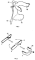
- Fig. 1 shows a perspective view Device according to the invention for suctioning Liquids, especially saliva, from the oral cavity, the device consisting of a with a cavity provided suction element AE, one with this fixed connected pipe extension RF, a sleeve H and a Support element SE consists of a chin rest KST, a Insert opening EO and a coupling point KS.
- the suction element AE is preferably U-shaped and has on its underside and on the side and its top hole L on, through the saliva or other liquids to be removed from the oral cavity be sucked off by a negative pressure in the cavity of the Suction element AE is generated.
- the cavity is on the other hand connected to the tubular extension RF, which with the Suction element AE is preferably firmly connected and the L-shaped is formed, the two flanks of the Pipe extension RF preferably an angle of 80 degrees lock in.
- Fig. 1 from a detailed representation D is the inner Structure of the suction element AE can be seen, in this Detail representation D a cross section through a branch of U-shaped suction element AE is shown.
- Recognizable is a by support units ST and a coating U formed cavity, which through the holes L to the outside, d. H. with the oral cavity, and in which the liquids to be suctioned off and to the pipe extension RF to be transported.
- The preferably from one plastically deformable material, preferably made of Support units ST formed from copper wire convey this Coating U has a fixed shape, but due to the Flexibility of the material used for the Support units ST can be changed and adapted as required can. This makes the suction element AE easier To the appropriate individual form of a Adjust the oral cavity.
- the support element SE which can be separated from the suction element AE has an outer shape, which is a negative deduction of a "normal trained "human chin the support element SE form-fitting to a chin nestle.
- the support element SE also has a Fitting opening EO and a coupling point KS that are interconnected and preferably on one axis are aligned. While over the coupling point KS Hose SC can be connected to the other side connected to a pump - not shown in Fig. 1 is in the fitting opening EO the pipe extension RF recordable, this using the sleeve H in the Fitting opening EO is held.
- the sleeve H an inner diameter that corresponds to the outer diameter of the Pipe extension RF corresponds, and an outer Diameter which corresponds to the inner diameter of the Fitting opening corresponds to EO. So when inserting the with the sleeve H provided pipe extension RF in the Fitting opening EO, the sleeve H does not disappear in it, the sleeve H additionally has a collar which according to the completely inserting stands on the support element SE.
- the sleeve H becomes conically wider towards the collar and becomes an elastic material, such as rubber, for the Sleeve H used, so the adhesive effect and thus the Connection between suction element AE and support element SE further improved. This will increase the stability of the Overall device also improved.
- FIG. 2 shows the device according to the invention according to FIG. 1 in assembled condition.
- Fig. 3 is the structure of an inventive Suction element AE shown, Fig. 3A the Support unit ST shows, preferably with wire Copper is formed.
- the support unit ST comes with a T-shaped coating U according to FIG. 3B, which is made of an elastically deformable material is formed.
- U-shaped suction element AE In order to can be any shape for the suction elements AE form, in particular like that shown in Fig. 3C U-shaped suction element AE.
- FIG Cross-section shown, now in the oral cavity a patient is used.
- the Type of attachment of the device according to the invention Particularly clear: The suction element AE is attached to the Lower jaw clamped tightly, so that no auxiliary person is needed, which leads the suction element AE.
- the suction element AE after Is thrown away while the support element SE is reusable.
- this Suction element AE to a height that prevents the Tongue of the patient over the suction element AE the teeth can slide and thus the work of the treating person difficult or even disabled. It is the goal is not to push the tongue down, but rather by appropriate support on one hold specific place.
Landscapes
- Health & Medical Sciences (AREA)
- Dentistry (AREA)
- Epidemiology (AREA)
- Life Sciences & Earth Sciences (AREA)
- Animal Behavior & Ethology (AREA)
- General Health & Medical Sciences (AREA)
- Public Health (AREA)
- Veterinary Medicine (AREA)
- Oral & Maxillofacial Surgery (AREA)
- Hooks, Suction Cups, And Attachment By Adhesive Means (AREA)
- Dental Tools And Instruments Or Auxiliary Dental Instruments (AREA)
Abstract
Description
- Fig. 1
- Bestandteile einer erfindungsgemässen Vorrichtung in perspektivischer Darstellung,
- Fig. 2
- die vollständig zusammengesetzte erfindungsgemässe Vorrichtung gemäss Fig. 1,
- Fig. 3
- ein erfindungsgemässes Stützelement,
- Fig. 4
- die bei einem Patienten eingesetzte erfindungsgemässe Vorrichtung in Querschnittdarstellung und
- Fig. 5
- die bei einem Patienten eingesetzte erfindungsgemässe Vorrichtung in perspektivischer Darstellung.
Claims (8)
- Vorrichtung zum Absaugen von in der Mundhöhle angesammelter Flüssigkeiten, dadurch gekennzeichnet, dass ein mindestens ein Loch (L) aufweisendes Absaugelement (AE) und ein Stützelement (SE) vorgesehen sind, wobei zur exakten Positionierung des Absaugelementes (AE) in der Mundhöhle dieses mit dem Stützelement (SE) über ein Verbindungselement (RF, H, EO, KS) verbindbar ist.
- Vorrichtung nach Anspruch 1, dadurch gekennzeichnet, dass das Stützelement (SE) im wesentlichen ausserhalb und das Absaugelement (AE) im wesentlichen innerhalb der Mundhöhle positioniert ist, wobei das Stützelement (SE) auf der dem Absaugelement (AE) zugewandten Seite derart ausgebildet ist, dass sich das Stützelement (SE) im wesentlichen formschlüssig an das Kinn anschmiegt.
- Vorrichtung nach Anspruch 1 oder 2, dadurch gekennzeichnet, dass das Absaugelement (AE) flexibel formbar ist und vorzugsweise U-förmig ausbildbar ist.
- Vorrichtung nach einem der vorangehenden Ansprüche, dadurch gekennzeichnet, dass das Absaugelement (AE) aus einer Stützeinheit (ST), vorzugsweise aus Draht, und einem Überzug (U) besteht, dass der Überzug (U) die Stützeinheit (ST) vollständig umfasst und im Bereich der Auflage in der Mundhöhle mehrere Löcher (L) aufweist.
- Vorrichtung nach einem der vorangehenden Ansprüche, dadurch gekennzeichnet, dass das Verbindungselement (RF, H, EO, KS) aus einem, vorzugsweise L-förmigen, mit dem Absaugelement (AE) verbundenen Rohrfortsatz (RF), einer Hülse (H) und einer im Stützelement (SE) enthaltenen Einpassöffnung (EO) besteht, wobei der Rohrfortsatz (RF) mittels der Hülse (H) in der Einpassöffnung (EO) arretiert wird.
- Vorrichtung nach Anspruch 5, dadurch gekennzeichnet, dass am Stützelement (SE) eine Koppelstelle (KS) zum Anschliessen eines Absaugschlauches (SC) vorgesehen ist, wobei der Absaugschlauch (SC) mit dem Rohrfortsatz (RF) wirkverbindbar ist.
- Vorrichtung nach einem der vorangehenden Ansprüche, dadurch gekennzeichnet, dass das Absaugelement (AE) eine Höhe aufweist, die das seitlich Abgleiten der Zunge über das Absaugelement (AE) hinweg verhindert.
- Vorrichtung nach einem der Ansprüche 1 bis 7, dadurch gekennzeichnet, dass das Absaugelement als biegbare, in einer Ebene im wesentlichen der zum Verbindungselement ausgedehnte Rohrkammer ausgebildet ist, mit Öffnungen gerichtet im wesentlichen parallel zum Verbindungselement nach oben und/oder nach unten und/oder in der Ebene und/oder bezüglich der Rohrkammer endständig.
Applications Claiming Priority (3)
| Application Number | Priority Date | Filing Date | Title |
|---|---|---|---|
| CH120697 | 1997-05-23 | ||
| CH1206/97 | 1997-05-23 | ||
| CH120697 | 1997-05-23 |
Publications (2)
| Publication Number | Publication Date |
|---|---|
| EP0879581A2 true EP0879581A2 (de) | 1998-11-25 |
| EP0879581A3 EP0879581A3 (de) | 2000-05-24 |
Family
ID=4204988
Family Applications (1)
| Application Number | Title | Priority Date | Filing Date |
|---|---|---|---|
| EP98109179A Withdrawn EP0879581A3 (de) | 1997-05-23 | 1998-05-20 | Vorrichtung zum Absaugen von Flüssigkeiten |
Country Status (1)
| Country | Link |
|---|---|
| EP (1) | EP0879581A3 (de) |
Cited By (2)
| Publication number | Priority date | Publication date | Assignee | Title |
|---|---|---|---|---|
| WO2016168947A1 (es) * | 2015-04-20 | 2016-10-27 | Rippes Silva Ignacio | Dispositivo que se instala en la boca para la aislacion de un area dental que facilita un correcto tratamiento odontologico |
| US10667889B2 (en) | 2015-04-20 | 2020-06-02 | Dentaltor, Inc. | Device to be fitted in the mouth in order to isolate a dental area, facilitating correct dental treatment |
Family Cites Families (4)
| Publication number | Priority date | Publication date | Assignee | Title |
|---|---|---|---|---|
| FR777534A (fr) * | 1934-07-26 | 1935-02-22 | Appareil de captage de la salive au cours des interventions dentaires | |
| US3101543A (en) * | 1961-05-15 | 1963-08-27 | Herbert A Baughan | Dental saliva ejectors |
| US3091859A (en) * | 1961-07-19 | 1963-06-04 | Herbert A Baughan | Dental saliva ejectors |
| FR2572926A1 (fr) * | 1984-11-13 | 1986-05-16 | Namias Michel | Pompe a salive avec cale mentonniere |
-
1998
- 1998-05-20 EP EP98109179A patent/EP0879581A3/de not_active Withdrawn
Non-Patent Citations (1)
| Title |
|---|
| None |
Cited By (2)
| Publication number | Priority date | Publication date | Assignee | Title |
|---|---|---|---|---|
| WO2016168947A1 (es) * | 2015-04-20 | 2016-10-27 | Rippes Silva Ignacio | Dispositivo que se instala en la boca para la aislacion de un area dental que facilita un correcto tratamiento odontologico |
| US10667889B2 (en) | 2015-04-20 | 2020-06-02 | Dentaltor, Inc. | Device to be fitted in the mouth in order to isolate a dental area, facilitating correct dental treatment |
Also Published As
| Publication number | Publication date |
|---|---|
| EP0879581A3 (de) | 2000-05-24 |
Similar Documents
| Publication | Publication Date | Title |
|---|---|---|
| DE3048223C2 (de) | Konnektions-System für Gas-Leitungen mit ineinandersteckbaren Verbindungselementen für Beatmungs- bzw. Anästhesie-Geräte | |
| EP0711568B1 (de) | Absaugkatheter | |
| DE60201120T2 (de) | Vorrichtung zur Auffindung der Position von Schraubenlöchern zur Fixierung eines Markraumnagels | |
| DE60206295T2 (de) | Chirurgisches hilfsinstrument | |
| DE2915425C2 (de) | Saugsteuervorrichtung für ein Endoskop | |
| DE2428855B2 (de) | Vorrichtung zum Offenhalten des Mundes | |
| DE4000380A1 (de) | Befestigungsflansch fuer einen katheter | |
| DE112014001466T5 (de) | Flexibler Arm und Verfahren zu dessen Verwendung | |
| DE2605004B2 (de) | Vorrichtung zum ansaugen von blut eines patienten und zur behandlung des blutes mit einem antikoagulans | |
| CH622949A5 (de) | ||
| DE3417183C2 (de) | ||
| DE3889960T2 (de) | Ansatz für Sauger. | |
| DE60038385T2 (de) | Saugverbindungsstück und damit versehener katheter | |
| EP0879581A2 (de) | Vorrichtung zum Absaugen von Flüssigkeiten | |
| EP0845278B1 (de) | Befestigungssystem z.B. für ein medizinisches Instrument | |
| DE3006518C2 (de) | Vorrichtung zum Fixieren des Oberschenkelhalses und des großen Rollhügels am Schaft eines Oberschenkelknochens | |
| EP0842674B1 (de) | Drainagesystem | |
| DE2621767A1 (de) | Speichelsaugduese | |
| EP0081857A1 (de) | Winkelbohrlehre | |
| EP0934756A2 (de) | Kapillar-Drainageschlauch-System | |
| DE4015468C2 (de) | ||
| DE3216017C2 (de) | Vorrichtung zum Versorgen eines Osteotomiegebietes mit steriler Kühlflüssigkeit | |
| DE29503099U1 (de) | Dauerkanüle, insbesondere zur subkutanen Infusion | |
| DE3623367A1 (de) | Kupplungseinrichtung fuer narkose- und beatmungsgeraete | |
| DE29711829U1 (de) | Schnellspannklammer für eine Wundspreizvorrichtung |
Legal Events
| Date | Code | Title | Description |
|---|---|---|---|
| PUAI | Public reference made under article 153(3) epc to a published international application that has entered the european phase |
Free format text: ORIGINAL CODE: 0009012 |
|
| AK | Designated contracting states |
Kind code of ref document: A2 Designated state(s): AT BE CH CY DE DK ES FI FR GB GR IE IT LI LU MC NL PT SE |
|
| AX | Request for extension of the european patent |
Free format text: AL;LT;LV;MK;RO;SI |
|
| PUAL | Search report despatched |
Free format text: ORIGINAL CODE: 0009013 |
|
| AK | Designated contracting states |
Kind code of ref document: A3 Designated state(s): AT BE CH CY DE DK ES FI FR GB GR IE IT LI LU MC NL PT SE |
|
| AX | Request for extension of the european patent |
Free format text: AL;LT;LV;MK;RO;SI |
|
| AKX | Designation fees paid | ||
| REG | Reference to a national code |
Ref country code: DE Ref legal event code: 8566 |
|
| STAA | Information on the status of an ep patent application or granted ep patent |
Free format text: STATUS: THE APPLICATION IS DEEMED TO BE WITHDRAWN |
|
| 18D | Application deemed to be withdrawn |
Effective date: 20001201 |