EP0879649B1 - Vibrateur à air comprimé - Google Patents
Vibrateur à air comprimé Download PDFInfo
- Publication number
- EP0879649B1 EP0879649B1 EP98401106A EP98401106A EP0879649B1 EP 0879649 B1 EP0879649 B1 EP 0879649B1 EP 98401106 A EP98401106 A EP 98401106A EP 98401106 A EP98401106 A EP 98401106A EP 0879649 B1 EP0879649 B1 EP 0879649B1
- Authority
- EP
- European Patent Office
- Prior art keywords
- chamber
- vibrator
- vibratory element
- axial bore
- axial
- Prior art date
- Legal status (The legal status is an assumption and is not a legal conclusion. Google has not performed a legal analysis and makes no representation as to the accuracy of the status listed.)
- Expired - Lifetime
Links
Images




Classifications
-
- B—PERFORMING OPERATIONS; TRANSPORTING
- B06—GENERATING OR TRANSMITTING MECHANICAL VIBRATIONS IN GENERAL
- B06B—METHODS OR APPARATUS FOR GENERATING OR TRANSMITTING MECHANICAL VIBRATIONS OF INFRASONIC, SONIC, OR ULTRASONIC FREQUENCY, e.g. FOR PERFORMING MECHANICAL WORK IN GENERAL
- B06B1/00—Methods or apparatus for generating mechanical vibrations of infrasonic, sonic, or ultrasonic frequency
- B06B1/18—Methods or apparatus for generating mechanical vibrations of infrasonic, sonic, or ultrasonic frequency wherein the vibrator is actuated by pressure fluid
-
- A—HUMAN NECESSITIES
- A61—MEDICAL OR VETERINARY SCIENCE; HYGIENE
- A61C—DENTISTRY; APPARATUS OR METHODS FOR ORAL OR DENTAL HYGIENE
- A61C17/00—Devices for cleaning, polishing, rinsing or drying teeth, teeth cavities or prostheses; Saliva removers; Dental appliances for receiving spittle
- A61C17/16—Power-driven cleaning or polishing devices
- A61C17/20—Power-driven cleaning or polishing devices using ultrasonic waves
Definitions
- the present invention relates to a vibrator for generating vibration under the action of a working fluid under pressure such as compressed air. More particularly, this invention is concerned with improvements in a vibrator of the type having a disc-shaped vibratory element or vibration generating element.
- United States Patent No. 4,453,919 discloses an air-driven vibrator having a body defining a disc-shaped working chamber in which a disc-shaped vibratory element or rotor made of steel is received for oscillatory movement, a plurality of air injection ports being arranged tangentially to the working chamber to inject compressed air therein to thereby excite the vibratory element, the vibrator further having an exhaust port for discharging used air.
- the vibrator may be incorporated, for example, in a dental scaler to oscillate a vibratory tool adapted to remove calculus or plaque from teeth.
- the vibratory element When after use the supply of compressed air is terminated, the vibratory element, no longer excited, will cease to rotate and will therefore fall vertically downwards within the working chamber under the action of the gravity.
- the particular part of the wall of the working chamber upon which the vibratory element will finally rest and the angular position in which the vibratory element will finally repose will be dictated by the angular position of the working chamber relative to the vertical.
- the end faces of the vibratory element and the inner end walls of the working chamber be finished by a lapping machine in order to enhance the degree of dimensional precision thereof.
- the specular surfaces of the element and chamber walls thus formed by lapping finishing would cause the vibratory element to stick more strongly to the chamber walls.
- the vibratory element In the event that the vibratory element once sticks to the inner walls of the working chamber, the vibratory element would not resume its movement merely by reopening the air supply. To restart the vibrator, the vibratory element must be separated or detached away from the inner walls of the working chamber by hammering the vibrator or otherwise giving impact thereon.
- United States Patent No. 4,453,919 solved this problem of sticking by conically tapering the axial end faces of the vibratory element at a small angle by chamfering along the circumferential edges of the element, as shown in Figures 5A-5H and Figure 6B thereof, to ensure that the vibratory element is separated from the inner walls of the working chamber by air jets blown into the wedge-shaped space formed between the conical end face of the element and the flat inner wall of the working chamber.
- a disc-shaped unfinished vibratory element 1 prepared by cutting a steel rod is chucked by a chucking device 2 of a rotary workpiece holder of the cylindrical grinding machine as shown in FIG. 1 of the accompanying drawings, and the axis 3 of the workpiece holder is positioned at an angle, for example, of 88° relative to an axis 5 of a grinder wheel 4 as shown in FIG. 2.
- the vibratory element 1 as chucked by the chuck 2 is translated forward toward the rotating grinder wheel 4 as the element is rotated about the axis 3 of the workpiece holder. In this manner, one of the end faces of the element 1 is ground and chamfered conically at a small angle of 2°.
- the semifinished vibratory element is detached from the chuck of the workpiece holder and, after being turned over for 180°, the element is again chucked and ground to chamfer the other end face.
- the problem encountered in the conventional process for chamfering the vibratory elements is that the vibrators used and incorporated in dental handpieces are so small in size that the axial thickness of the vibratory elements is extremely thin, it being on the order of only 1 mm. Accordingly, it has been difficult to properly chuck the vibratory elements in the workpiece holder of the cylindrical grinding machine. In particular, it has been extremely difficult to chuck those elements having one of the end faces already subjected to chamfering.
- an object of the present invention is to provide a vibrator of the type described, which does not require chamfering of the vibratory element and which is yet operable without fail whenever injection of compressed air is commenced.
- Another object of the invention is to provide a vibrator of the type described, which is free from the problem of sticking of the vibratory element and which is comprised of those component parts which can be manufactured with a high production yield.
- a still another object of the invention is to provide a vibrator of the type described, wherein sticking of the vibratory element is effectively prevented and which is easy to manufacture.
- a further object of the invention is to provide a vibrator of the type described, which is free from the problem of sticking of the vibratory element and which has a structure that permits manufacture by the mass production process.
- Another object of the invention is to provide a vibrator of the type described, which consists of component parts which can be fabricated with a uniformly high quality.
- This invention provides a vibrator having a rigid body having a disk-shaped working chamber, a disc-shaped vibratory element received in the chamber for oscillatory movement, means for injecting a working fluid under pressure into the chamber in a tangential direction, and means for exhausting used working fluid out of the chamber.
- the feature of the invention is that axial end faces of the vibratory element are made substantially flat and that the body is provided with a projection protruding axially inwardly of at least one of the opposite end walls of the chamber.
- the terms "axially inwardly” and “axially outwardly” refer, respectively, to the axial direction toward and away from the center of the vibrator body.
- the projection provided on the end wall of the chamber serves to prevent the axial end wall of the vibratory element from being brought into close contact with the end wall of the chamber to thereby prevent sticking of the vibratory element when the vibrator is not operated. Due to the provision for the projection, a gap is always secured between the axial end wall of the vibratory element and the end wall of the chamber during the inoperative condition of the vibrator, although the axial end faces of the vibratory element are machined flat. Accordingly, upon commencement of injection of compressed air into the working chamber, the vibratory element is readily put into motion to generate vibration.
- the vibratory elements can be manufactured in an extremely simple manner as compared with the conventional method of manufacture.
- the elements' axial end faces that are flat may be machined with a high degree of precision by using a planar grinding machine and a lapping machine so that the production yield of the vibratory element is remarkably increased.
- planar grinding and lapping operations may be carried out on a batch basis for a large number of workpieces at a time. Accordingly, it is possible to manufacture the vibratory element by a mass production process.
- the projection may be made integrally with the inner end wall of the working chamber by any suitable process such as soldering, relieving of the end wall and the like. However, according to a preferred embodiment of the invention, the projection is made separate from the part forming the inner wall of the working chamber.
- an end plate defining the inner wall of the working chamber is provided with an axial bore in which an insert member having an extension protruding axially inwardly of the end wall of the chamber is fixed such as by press-fitting.
- the end face of the end plate may be made flat, the end plate may be machined by planar grinding and lapping in a simple manner and with a high degree of accuracy.
- the insert members may be manufactured separately from the end plates by a mass production process. The end plate and the insert member are readily assembled together in the case that the insert member is mounted in the bore of the end plate by press-fit.
- the insert member is in the form of a collar having an axial bore which forms part of the exhaust passage.
- the collar is arranged coaxially with the body of the vibrator.
- the axial end faces of the vibratory element are made flat and the element is provided with a central bore in which an insert member is inserted in a manner to protrude axially outwardly of the axial end faces of the vibratory element.
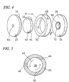
- the vibrator 10 includes a body 12 made, for example, of steel.
- the body 12 has a cylindrical outer casing 14 in which a bore 18 having an axis 16 is formed.
- the body 12 further includes a tubular air injection ring 20 arranged coaxially in the bore 18 and a pair of opposite disc-shaped end plates 22 and 24 disposed on both sides of the ring 20.
- the injection ring 20 and the end plates 22 and 24 are held together within the outer casing 14 by a threaded retainer 28 screwed into an internal thread 26 of the outer casing 14.
- the retainer 28 is provided with a pair of diametrically opposite holes 30 designed to be engaged by a spanner.
- a disc-shaped working chamber or rotor chamber 38 is defined by the circumferential inner face 32 of the injection ring 20, the inner end face 34 of the end plate 22, and the inner end face 36 of the end plate 24.
- a disc-shaped vibratory element or rotor 40 is movably and freely received in the working chamber 38.
- the vibratory element or vibration generating element 40 is defined by a pair of opposite flat axial end faces 42 and a cylindrical outer face 44.
- the axial and radial sizes of the vibratory element 40 are selected to be slightly smaller than the axial and radial sizes of the working chamber 38 to ensure that the vibratory element 40 is received in the working chamber 38 with a small clearance therebetween.
- the vibratory element 40 and the end plates 22 and 24 are preferably made of a highly wear resistant material such as high speed steel.
- a planar grinding machine it is preferable that, after heat treatment and grinding by a planar grinding machine, the vibratory element 40 as well as the end plates 22 and 24 are subjected to precision machining by a lapping machine to finish the end faces thereof.
- planar grinding and lapping of the vibratory elements 40 and end plates 22 and 24 are carried out on a batch basis for a substantial number of workpieces at a time, so as to ensure that the vibrators are manufactured by a mass production process.
- the injection ring 20 is provided with a plurality of injection ports or nozzles 46, numbering three, for example. As will be understood from FIG. 5, the injection ports 46 are open tangentially into the working chamber 38 so as to produce a swirling air stream 48 in the chamber 38.
- the outer casing 14 is provided with an annular groove 50 facing the injection ports 46, the groove 50 being in communication with an inlet fitting 54 through a radial port 52.
- the inlet fitting 54 may be connected to a source of compressed air through an air hose, not shown. As compressed air is supplied to the inlet fitting 54, air is injected through the injection ports 46 tangentially into the working chamber 38 to thereby generate a swirl of air 48 within the chamber 38.
- Used air is discharged to the ambient atmosphere through an exhaust port 58 formed coaxially across the end plate 24 and another exhaust port 60 formed coaxially across the retainer 28, the ports 58 and 60 serving as exhaust means.
- the end plate 22 is formed with a coaxial bore 62 in which an insert 64 in the form of a short rod is press-fit.
- the axial length of the insert member 64 is made slightly greater than the axial thickness of the end plate 22 to ensure that the inner end of the insert 64 forms a projection 66 that protrudes from the inner end face 34 of the end plate 22 axially inwardly toward the working chamber 38.
- the projection 66 serves to prevent the vibratory element 40 from sticking to the inner end face of the end plate 22 when the vibrator is not operated.
- an insert 68 in the form of a collar.
- the collar 68 is provided therethrough with an axial bore 70 which actually serves as an exhaust passage. Similar to the insert 64, the axial length of the collar 68 is made slightly greater than the axial thickness of the end plate 24, so that the annular inner end 72 of the collar 68 projects axially inwardly from the inner face 36 of the end plate 24 into the working chamber 38. Similar to the projection 66, the annular extension 72 of the collar 68 serves as a projection for preventing the vibratory element 40 from sticking to the inner end face of the end plate 24.
- the sub-assembly consisting of the end plate 22 and the insert 64 may be made similar to and replaced with the sub-assembly made of the end plate 24 and the collar 68.
- the diameter of the collar 68 must be selected smaller enough than the diameter of the wear print 56 (FIG. 6) of the vibratory element 40 in order to avoid that the element 40 is interfered by the projection 72 as the element is rotated or oscillated.
- the axial height of the projections 66 and 72 as measured from the inner end faces 34 and 36 of the end plates must be limited such that the projections 66 and 72 would not interfere with the vibratory element 40 as it is moved.
- the axial height of the projections 66 and 72 is preferably precision controlled by subjecting the sub-assembly of the end plate 22 and the insert 64 as well as the sub-assembly of the end plate 24 and the collar 68 to planar grinding followed by lapping.
- the sub-assemblies may be assembled by first fabricating the inserts 64 and 68 having a precisely controlled axial length and by then press-fitting them into the axial bores of the end plates 22 and 24, respectively.
- the body 12 of the vibrator may be suitably coupled in a vibration transmitting relationship to an object to be vibrated.
- an air hose is connected to the inlet fitting 54 and compressed air is supplied causing air to be injected through the injection ports 46 into the working chamber 38, the vibratory element 40 is rotated and strikes the end plates 22 and 24, as described hereinbefore with reference to FIG. 6, whereby vibration is generated and is transmitted to the object.
- the projections 66 and 72 will not hinder the vibratory or oscillatory movement of the element 40 since the axial height and the radial dimension of the projections 66 and 72 are selected not to interfere with the moving element 40 as described before.
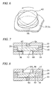
- the vibratory element 40 will rest upon the annular projection 72 of the collar 68 as shown typically in FIG. 7.
- the axial end face 42 of the element 40 will be spaced away from the inner end face 36 of the end plate 24 by a distance equal to the height of the projection 72.
- the projection 72 acts to prevent the axial end face 42 of the element 40 and the inner end face 36 of the end plate 24 from being brought into contact with each other.
- the edge of the vibratory element 40 will be in contact with the inner end face 34 of the plate 22, whereas the region of the edge diametrically opposite to the point of contact will be lifted away from the inner end face 34 due to the presence of the projection 66. Accordingly, when supply of compressed air is resumed, air jets will be blown into the wedge-shaped gap formed between the axial end face 42 of the element 40 and the inner end face 36 of the end plate 24 so that the vibratory element 40 will readily restart its vibratory movement.
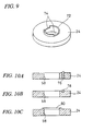
- FIG. 9 illustrates a modified version of the collar 68 of the end plate 24.
- the annular projection 72 of the collar 68 is provided with diametrically opposite cutouts 74.
- FIGS. 10A-10C show modified forms of the projection formed on the end plate 24.
- an axial bore is formed through the end plate 24 at a position radially outwardly offset from the exhaust port 58, in which bore a pin 76 having a length slightly greater than the axial thickness of the end plate 24 is interference fitted.
- a steel ball 78 is fixed within a cavity on the end plate 24 to form the projection.
- an annular projection 80 adjacent to and surrounding the exhaust port 58 is integrally formed on the end plate 24.
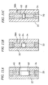
- FIGS. 11A-11C illustrate other embodiments of the vibrator wherein the projection is formed on the vibratory element 40.
- the vibratory element 40 is provided with a central bore in which a collar 82 having a length slightly longer than the axial thickness of the element 40 is press-fitted in such a manner as to protrude beyond the axial end faces of the element 40.
- the outer diameter of the collar 82 is selected to be greater than the inner diameter of the exhaust port 58 in order to preclude the vibratory element 40 from becoming in contact with the inner end wall 36 of the end plate 24 when the vibrator is not operated.
- the vibratory element 40 is formed with a central bore in which a steel ball 84 having a diameter slightly greater than the axial thickness of the element 40 is press-fitted.
- the exhaust port 58A is formed through the end plate 24 at a position radially outwardly offset from the axis of the plate.
- an insert 86 in the form of a short rod having a length slightly greater than the thickness of the vibratory element 40 is press-fitted in the central bore of the element 40.
- the vibratory element 40 is prevented from adhering to the inner walls of the end plates 22 and 24 during the inoperative condition of the vibrator.
- FIGS. 12-14 there is shown a dental scaler wherein a vibrator according to another embodiment of the invention is incorporated.
- the dental scaler is designed and constructed in the form of an air-driven handpiece which is adapted to be connected through a dental hose to a conventional dental unit for a supply of compressed air.
- the dental scaler 100 has an outer casing 102 adapted to be held by a hand.
- the outer casing 102 may include a frontal casing 104, a threaded joint fitting 106 screwed into the internal thread formed at the rear end of the frontal casing 104, a rear casing 108 screwed onto the external thread formed at the rear end of the joint 106, and a threaded end member 110 screwed into the internal thread at the rear end of the rear casing 108.
- the end member 110 is provided at its rear end with an external thread 112 which is adapted to be engaged by a conventional hose joint 116 for connecting the handpiece with a packing 114 to a dental hose 118 extending from a conventional dental unit, not shown.
- a vibrator 120 according to the invention is accommodated within the frontal casing 104 and is located in the axial direction by screwing the joint fitting 106 into the frontal casing 104.
- the vibrator 120 is resiliently supported, and is isolated in vibration against the frontal casing 104 and the joint 106, by a plurality of elastomeric O-rings, only one of which is indicated in FIG. 13 by the reference numeral 122.
- the vibrator 120 includes an outer casing 124 having a stepped bore 126 extending along the axis of the dental scaler 100.
- the frontal part of the bore 126 is formed with an internal thread 128 in which a threaded end of a scaling tool or tip 130 is detachably screwed.
- the scaling tool 130 has a water passage 132 extending axially through the shank thereof for supplying water so as to cool the teeth and the scaling tool during scaling operation and to wash away removed debris.
- Water under pressure is supplied from the dental unit to the water passage 132 through a water pipe 134, a radial passage 138 in the joint 106 closed at the outer end by a ball plug 136, a water pipe 140, and the bore 126.
- the vibrator 120 is similar in many respects to the embodiment shown in FIGS. 3-5.
- the vibrator 120 is comprised of a disc-shaped end plate 142, an air injection ring 144, and a disc-shaped end plate 146, in a manner similar to the embodiment shown in FIGS. 3-5, these component parts being held together by a threaded retainer 148 screwed into the outer casing 124 to thereby form a working chamber 150.
- a disc-shaped vibratory element 152 is movably received in the working chamber 150.
- the vibratory element 152 is provided with a central bore 154 to ensure that the water pipe 140 does not interfere with the movement of the vibratory element 152.
- the axial size of the vibratory element 152 is preferably about 1-1.5 mm, with the outer diameter of the element 152 to be about 5-8 mm, the axial size of the working chamber 150 to be greater by about 0.5-1 mm than the axial size of the element 152, and the inner diameter of the chamber 150 to be greater by about 0.5-2 mm than the outer diameter of the element 152.
- Tangentially directed air injection ports 156 of the injection ring 144 is communicated through an inner groove 158 of the outer casing 124 and radial ports 160 with an annular space 162 (FIG. 13) formed between the outer periphery of the outer casing 124 and the inner periphery of the frontal casing 104.
- Compressed air from a dental unit is fed to the injection ring 144 through an air pipe 164, an axially extending air passage 166 formed in the joint fitting 106 at a position radially outwardly offset from the axis of the dental scaler, a radial passage 168 in the joint 106, and the annular space 162.
- An O-ring 169 tightly fitted between the water pipe 140 and the casing 124 serves to prevent air in the working chamber 150 from leaking forwardly thereof.
- Used air in the working chamber 150 is delivered through an exhaust port 170 in the end plate 146 and a central port 172 in the retainer 148 to a space 174 formed between the retainer 148 and the joint 106, and is forwarded therefrom back to the dental unit through an axially extending exhaust passage 176 formed in the joint 106 at a position radially outwardly offset from the axis of the dental scaler, an inner space 178 in the rear casing 108, an exhaust pipe 180, and the dental hose 118.
- the end plates 142 and 146 are made identical in order to provide a commonality of component parts. Therefore, only one of them will be described. Similar to the end plate 24 shown in FIGS. 3 and 4, the end plate 146 has a central bore 182 in which a collar 184 is press-fitted. A bore 170 in the collar 184 acts as an exhaust port for used air. The collar 184 has an outer diameter larger than the inner diameter of the vibratory element 152.
- the inner end of the collar 184 protrudes slightly into the working chamber 150 beyond the inner end face of the end plate 146.
- the vibratory element 152 and the working chamber 150 are sized and dimensioned as described hereinbefore, it will be sufficient to prevent the vibratory element 152 from sticking to the end plate 146 during the inoperative state of the vibrator if the amount of projection of the inner end of the collar 184 as measured from the inner end face of the end plate 146 is equal to about 50 ⁇ m. With this amount of projection, the vibratory element would never interfere with the collar 184 during oscillation.
- end plates 142 and 146 and the associated collars 184 may be manufactured in a manner similar to that described with reference to the embodiment of FIGS. 3-5 and may be assembled in a similar manner.
- Vibration generated by the vibrator 120 is transmitted through the casing 124 to the scaling tool 130 to oscillate the tip of the tool 130 to remove calculus or plaque from the teeth.
- the collars 184 slightly protruding from the inner end faces of the end plates 142 and 146 will preclude the vibratory element 152 from sticking to the end plates, as will be apparent from the foregoing description made with reference to FIG. 7. As a result, the vibratory element 152 will be again put into motion without fail as soon as the supply of compressed air is restarted.
- the present inventor has made and tested a dental scaler as shown in FIGS. 12-14.
- the scaler was tested by intermittently operating the vibrator by interrupting air supply for 2 seconds for every 2 seconds of air supply. Throughout 23,400 cycles of intermittent operation, carried out for total 13 working hours, the vibratory element was restarted fully successfully, without causing sticking to the end plates.
- the vibrators according to the invention may be used in any desired application other than dental scalers.
- the number of component parts of the vibrator, the structure and configuration of the vibrator, the position and arrangement of the air passages, and the number and angle of air injection ports may be modified as required.
Landscapes
- Health & Medical Sciences (AREA)
- Animal Behavior & Ethology (AREA)
- Mechanical Engineering (AREA)
- Dentistry (AREA)
- Epidemiology (AREA)
- Life Sciences & Earth Sciences (AREA)
- Engineering & Computer Science (AREA)
- General Health & Medical Sciences (AREA)
- Public Health (AREA)
- Veterinary Medicine (AREA)
- Dental Tools And Instruments Or Auxiliary Dental Instruments (AREA)
- Apparatuses For Generation Of Mechanical Vibrations (AREA)
- Surgical Instruments (AREA)
Claims (11)
- Vibreur comprenant un corps rigide (12, 20, 22, 24, 28) possédant une chambre de travail sensiblement en forme de disque (38) définie par une paroi latérale cylindrique (32), et une paire de parois d'extrémité opposées (34, 36) s'étendant perpendiculairement à l'axe (16) de la chambre (38), un élément vibrant sensiblement en forme de disque (40) d'une taille plus petite que ladite chambre (38), et reçu dans ladite chambre (38) pour un mouvement oscillant, un moyen (46, 52, 54) pour injecter un fluide de travail gazeux sous pression dans ladite chambre (38) dans une direction tangentielle par rapport à ladite chambre (38), pour produire un courant tourbillonnant (48) du fluide de travail à l'intérieur, et un moyen d'échappement (60, 70) pour évacuer de ladite chambre (38) le fluide de travail usagé, les faces d'extrémité axiale dudit élément vibrant (40) étant réalisées sensiblement plates, caractérisé en ce que ledit corps (12, 20, 22, 24, 28) est muni d'une protubérance (66, 72, 76, 78, 80) faisant saillie axialement vers l'intérieur à partir de l'une au moins desdites parois d'extrémité opposées (34, 36) de ladite chambre (38), pour empêcher ainsi l'élément vibrant (40) de se coller à ladite paroi d'extrémité (34, 36) lorsque le vibreur n'est pas en fonctionnement.
- Vibreur selon la revendication 1, dans lequel ledit corps comporte une plaque d'extrémité (22, 24) définissant l'une au moins desdites parois d'extrémité opposées (34, 36), ladite plaque d'extrémité (22, 24) étant traversée par un alésage axial (58, 62), un élément d'insertion (64, 68) étant fixement introduit dans ledit alésage axial (58, 62) de ladite plaque d'extrémité (22, 24), ledit élément d'insertion (64, 68) comportant un prolongement (66, 72) faisant saillie axialement vers l'intérieur à partir de ladite paroi d'extrémité (34, 36) pour former ainsi ladite protubérance.
- Vibreur selon la revendication 2, dans lequel ledit élément d'insertion (64, 68) est introduit dans ledit alésage axial (58, 62) de la plaque d'extrémité (22, 24) par montage à force.
- Vibreur selon la revendication 2 ou 3, dans lequel ledit alésage axial (58, 62) et ledit élément d'insertion (64, 68) sont coaxiaux avec ledit corps.
- Vibreur selon la revendication 4, dans lequel ledit élément d'insertion est sous la forme d'une douille (68) traversée par un alésage axial (70).
- Vibreur selon la revendication 5, dans lequel ledit alésage axial (70) dudit élément d'insertion (68) sert à constituer une partie dudit moyen d'échappement (60, 70).
- Vibreur selon la revendication 5 ou 6, dans lequel ledit prolongement (72) de la douille (68) est de forme annulaire.
- Vibreur selon la revendication 5 ou 6, dans lequel ledit prolongement (72) de la douille (68) est partiellement découpé (74) le long de sa circonférence.
- Vibreur selon l'une des revendications 1 à 8, dans lequel ledit élément vibrant (152) comporte un alésage axial (154) qui le traverse le long de son axe.
- Vibreur comprenant un corps rigide (20, 22, 24) possédant une chambre de travail sensiblement en forme de disque (38) définie par une paroi latérale cylindrique (32), et une paire de parois d'extrémité opposées (34, 36) s'étendant perpendiculairement à l'axe de la chambre (38), un élément vibrant sensiblement en forme de disque (40) d'une taille plus petite que ladite chambre (38), et reçu dans ladite chambre (38) pour un mouvement oscillant, un moyen (46, 52, 54) pour injecter un fluide de travail gazeux sous pression dans ladite chambre (38) dans une direction tangentielle par rapport à ladite chambre (38), pour produire un courant tourbillonnant (48) du fluide de travail à l'intérieur, et un moyen d'échappement (58, 58A) pour évacuer le fluide de travail usagé de ladite chambre (38), les faces d'extrémité axiale dudit élément vibrant (40) étant usinées de façon sensiblement plate, caractérisé en ce que ledit élément vibrant (40) comporte un alésage axial qui le traverse le long de son axe, un élément d'insertion (82, 84, 86) faisant saillie axialement vers l'extérieur desdites faces d'extrémité axiales dudit élément vibrant (40) est introduit fixement dans ledit alésage axial de l'élément vibrant (40) pour empêcher l'élément vibrant (40) de se coller à la paroi d'extrémité (34, 36) de la chambre (38) lorsque le vibreur n'est pas en fonctionnement.
- Vibreur selon la revendication 10, dans lequel ledit élément d'insertion (82) est sous la forme d'une douille coaxiale avec ledit alésage axial de l'élément vibrant (40).
Applications Claiming Priority (3)
| Application Number | Priority Date | Filing Date | Title |
|---|---|---|---|
| JP141056/97 | 1997-05-15 | ||
| JP14105697 | 1997-05-15 | ||
| JP14105697A JP3712829B2 (ja) | 1997-05-15 | 1997-05-15 | 空気動式バイブレータ |
Publications (2)
| Publication Number | Publication Date |
|---|---|
| EP0879649A1 EP0879649A1 (fr) | 1998-11-25 |
| EP0879649B1 true EP0879649B1 (fr) | 2004-09-08 |
Family
ID=15283237
Family Applications (1)
| Application Number | Title | Priority Date | Filing Date |
|---|---|---|---|
| EP98401106A Expired - Lifetime EP0879649B1 (fr) | 1997-05-15 | 1998-05-06 | Vibrateur à air comprimé |
Country Status (6)
| Country | Link |
|---|---|
| US (1) | US5997172A (fr) |
| EP (1) | EP0879649B1 (fr) |
| JP (1) | JP3712829B2 (fr) |
| CN (1) | CN1096840C (fr) |
| AT (1) | ATE275443T1 (fr) |
| DE (1) | DE69826061T2 (fr) |
Families Citing this family (11)
| Publication number | Priority date | Publication date | Assignee | Title |
|---|---|---|---|---|
| RU2235187C2 (ru) * | 2000-05-16 | 2004-08-27 | Иванников Владимир Иванович | Устройство для вибровоздействия на колонну труб в скважине (варианты) |
| US6752629B2 (en) * | 2001-02-26 | 2004-06-22 | Micron Co., Ltd. | Air-driven dental vibratory instrument with a replaceable vibrator module |
| US6571870B2 (en) | 2001-03-01 | 2003-06-03 | Schlumberger Technology Corporation | Method and apparatus to vibrate a downhole component |
| CN101088632B (zh) * | 2007-07-12 | 2010-06-02 | 中国科学院力学研究所 | 可控气体激振系统 |
| DE102007037129A1 (de) * | 2007-08-07 | 2009-02-19 | Sirona Dental Systems Gmbh | Zahnärztliches Handstück mit einer über ein Kupplungsstück mechanisch verbindbaren Werkzeugspitze |
| US9452027B2 (en) * | 2009-12-10 | 2016-09-27 | Kerrhawe Sa | Dental composite applicator and related methods |
| CN103100518A (zh) * | 2013-01-25 | 2013-05-15 | 卧龙电气集团股份有限公司 | 一种活塞内置式气动振动器 |
| CN103286058A (zh) * | 2013-05-24 | 2013-09-11 | 山东科技大学 | 活塞式风动强力振动器 |
| CN105414001A (zh) * | 2015-11-23 | 2016-03-23 | 高佳 | 一种高频振棒机高压气流发生器 |
| CN105559928A (zh) * | 2016-03-16 | 2016-05-11 | 暨泳锋 | 一种气动洁牙器 |
| WO2022198781A1 (fr) * | 2021-03-22 | 2022-09-29 | 桂林市啄木鸟医疗器械有限公司 | Structure de réglage de pression d'air |
Family Cites Families (9)
| Publication number | Priority date | Publication date | Assignee | Title |
|---|---|---|---|---|
| US2422639A (en) * | 1943-11-17 | 1947-06-17 | Vibro Plus Corp | Vibrating device |
| CH432909A (fr) * | 1960-08-22 | 1967-03-31 | Halilovic Esref | Vibrateur hydrodynamique |
| US3318163A (en) * | 1964-02-17 | 1967-05-09 | Vibrator Mfg Company | Vibration mechanism |
| SE370642B (fr) * | 1970-10-14 | 1974-10-28 | Wacker Werke Kg | |
| DE2706053A1 (de) * | 1977-02-12 | 1978-08-17 | Bosch Gmbh Robert | Elektromotorisch angetriebener unwuchtvibrator |
| US4453919A (en) * | 1981-04-24 | 1984-06-12 | Micron Co., Ltd. | Dental scaler |
| US4427384A (en) * | 1982-07-22 | 1984-01-24 | Sertich Anthony T | Vibratory dental scaler |
| US5190456A (en) * | 1986-09-26 | 1993-03-02 | Micron Co., Ltd. | Air-driven dental scaler |
| ATE60212T1 (de) * | 1986-09-26 | 1991-02-15 | Micron Co Ltd | Luftbetriebener zahnsteinentferner. |
-
1997
- 1997-05-15 JP JP14105697A patent/JP3712829B2/ja not_active Expired - Lifetime
-
1998
- 1998-04-28 US US09/066,766 patent/US5997172A/en not_active Expired - Lifetime
- 1998-05-06 DE DE69826061T patent/DE69826061T2/de not_active Expired - Lifetime
- 1998-05-06 EP EP98401106A patent/EP0879649B1/fr not_active Expired - Lifetime
- 1998-05-06 AT AT98401106T patent/ATE275443T1/de active
- 1998-05-15 CN CN98108432A patent/CN1096840C/zh not_active Expired - Lifetime
Also Published As
| Publication number | Publication date |
|---|---|
| DE69826061T2 (de) | 2005-09-29 |
| DE69826061D1 (de) | 2004-10-14 |
| JPH10314673A (ja) | 1998-12-02 |
| CN1096840C (zh) | 2002-12-25 |
| US5997172A (en) | 1999-12-07 |
| JP3712829B2 (ja) | 2005-11-02 |
| EP0879649A1 (fr) | 1998-11-25 |
| ATE275443T1 (de) | 2004-09-15 |
| CN1199601A (zh) | 1998-11-25 |
Similar Documents
| Publication | Publication Date | Title |
|---|---|---|
| US5997172A (en) | Air-driven vibrator | |
| EP0092861B1 (fr) | Dispositif vibratoire et nettoyeur dentaire incorporant celui-ci | |
| US7175506B2 (en) | Tool unit for ultrasonically assisted rotary machining | |
| KR100372609B1 (ko) | 그라인딩컵 | |
| US4289486A (en) | Pneumatic dental scaler | |
| EP0646435A1 (fr) | Dispositif d'usinage rotatif, structure adaptée, et outils rotatifs correspondants | |
| JPH11254324A (ja) | 研磨のための方法および装置 | |
| US4453919A (en) | Dental scaler | |
| US5749727A (en) | Transducer activated subgingival tool tip | |
| US6030216A (en) | Dentistry hand piece | |
| US4427384A (en) | Vibratory dental scaler | |
| JP3749777B2 (ja) | 工作物穴のエッジの端面、特に環状面を研削する装置 | |
| JPH10502546A (ja) | 変換器作動のツール・チップ | |
| JP4154504B2 (ja) | 研削カップ及びホルダー装置 | |
| JP2003024334A (ja) | 縫合針及びその製造方法 | |
| CA2239177C (fr) | Pointe d'outil subgingival activee par transducteur | |
| JPH0890403A (ja) | 光学素子の研削方法とその装置 | |
| JP2003170309A (ja) | バリ取り工具及びドリル加工等により発生する中空部材内面のバリ除去方法 | |
| JP4390909B2 (ja) | 弾性体膜取付具及びこれを用いた粉体材料噴霧装置 | |
| JPH0724709A (ja) | 回転工具を有する加工装置及び加工方法 | |
| JP3757601B2 (ja) | 孔の面取り加工方法 | |
| JPH04111705A (ja) | 内周切削工具 | |
| JPH0866866A (ja) | 研削ヘッド | |
| EP0270117A2 (fr) | Outil pour lentilles à montage rapide | |
| JP4522066B2 (ja) | 研削工具およびそれを用いた研削加工方法 |
Legal Events
| Date | Code | Title | Description |
|---|---|---|---|
| PUAI | Public reference made under article 153(3) epc to a published international application that has entered the european phase |
Free format text: ORIGINAL CODE: 0009012 |
|
| AK | Designated contracting states |
Kind code of ref document: A1 Designated state(s): AT CH DE FR GB IT LI |
|
| AX | Request for extension of the european patent |
Free format text: AL;LT;LV;MK;RO;SI |
|
| 17P | Request for examination filed |
Effective date: 19981118 |
|
| AKX | Designation fees paid |
Free format text: AT CH DE FR GB IT LI |
|
| GRAP | Despatch of communication of intention to grant a patent |
Free format text: ORIGINAL CODE: EPIDOSNIGR1 |
|
| RIC1 | Information provided on ipc code assigned before grant |
Ipc: 7A 61C 17/18 B Ipc: 7B 06B 1/18 A |
|
| GRAS | Grant fee paid |
Free format text: ORIGINAL CODE: EPIDOSNIGR3 |
|
| GRAA | (expected) grant |
Free format text: ORIGINAL CODE: 0009210 |
|
| AK | Designated contracting states |
Kind code of ref document: B1 Designated state(s): AT CH DE FR GB IT LI |
|
| REG | Reference to a national code |
Ref country code: GB Ref legal event code: FG4D |
|
| REG | Reference to a national code |
Ref country code: CH Ref legal event code: EP |
|
| REF | Corresponds to: |
Ref document number: 69826061 Country of ref document: DE Date of ref document: 20041014 Kind code of ref document: P |
|
| REG | Reference to a national code |
Ref country code: CH Ref legal event code: NV Representative=s name: DR. JOACHIM LAUER PATENTANWALT |
|
| ET | Fr: translation filed | ||
| PLBE | No opposition filed within time limit |
Free format text: ORIGINAL CODE: 0009261 |
|
| STAA | Information on the status of an ep patent application or granted ep patent |
Free format text: STATUS: NO OPPOSITION FILED WITHIN TIME LIMIT |
|
| 26N | No opposition filed |
Effective date: 20050609 |
|
| REG | Reference to a national code |
Ref country code: CH Ref legal event code: PCAR Free format text: DR. JOACHIM LAUER C/O RENTSCH PARTNER AG;FRAUMUENSTERSTRASSE 9 POSTFACH 2441;8022 ZUERICH (CH) |
|
| REG | Reference to a national code |
Ref country code: DE Ref legal event code: R082 Ref document number: 69826061 Country of ref document: DE Representative=s name: GRAMM, LINS & PARTNER PATENT- UND RECHTSANWAEL, DE |
|
| REG | Reference to a national code |
Ref country code: FR Ref legal event code: PLFP Year of fee payment: 19 |
|
| REG | Reference to a national code |
Ref country code: FR Ref legal event code: PLFP Year of fee payment: 20 |
|
| PGFP | Annual fee paid to national office [announced via postgrant information from national office to epo] |
Ref country code: DE Payment date: 20170502 Year of fee payment: 20 Ref country code: FR Payment date: 20170413 Year of fee payment: 20 Ref country code: GB Payment date: 20170503 Year of fee payment: 20 Ref country code: CH Payment date: 20170512 Year of fee payment: 20 |
|
| PGFP | Annual fee paid to national office [announced via postgrant information from national office to epo] |
Ref country code: AT Payment date: 20170425 Year of fee payment: 20 Ref country code: IT Payment date: 20170522 Year of fee payment: 20 |
|
| REG | Reference to a national code |
Ref country code: CH Ref legal event code: PCAR Free format text: NEW ADDRESS: BELLERIVESTRASSE 203 POSTFACH, 8034 ZUERICH (CH) |
|
| REG | Reference to a national code |
Ref country code: DE Ref legal event code: R071 Ref document number: 69826061 Country of ref document: DE |
|
| REG | Reference to a national code |
Ref country code: CH Ref legal event code: PL |
|
| REG | Reference to a national code |
Ref country code: GB Ref legal event code: PE20 Expiry date: 20180505 |
|
| REG | Reference to a national code |
Ref country code: AT Ref legal event code: MK07 Ref document number: 275443 Country of ref document: AT Kind code of ref document: T Effective date: 20180506 |
|
| PG25 | Lapsed in a contracting state [announced via postgrant information from national office to epo] |
Ref country code: GB Free format text: LAPSE BECAUSE OF EXPIRATION OF PROTECTION Effective date: 20180505 |