EP0879689A1 - Manchon de raccordement pour distributeurs de moulage par injection - Google Patents
Manchon de raccordement pour distributeurs de moulage par injection Download PDFInfo
- Publication number
- EP0879689A1 EP0879689A1 EP98107135A EP98107135A EP0879689A1 EP 0879689 A1 EP0879689 A1 EP 0879689A1 EP 98107135 A EP98107135 A EP 98107135A EP 98107135 A EP98107135 A EP 98107135A EP 0879689 A1 EP0879689 A1 EP 0879689A1
- Authority
- EP
- European Patent Office
- Prior art keywords
- connector bushing
- nonthreaded
- main body
- cylindrical portion
- heated
- Prior art date
- Legal status (The legal status is an assumption and is not a legal conclusion. Google has not performed a legal analysis and makes no representation as to the accuracy of the status listed.)
- Granted
Links
- 238000001746 injection moulding Methods 0.000 title claims abstract description 15
- 239000000463 material Substances 0.000 claims abstract description 13
- 229910000831 Steel Inorganic materials 0.000 claims abstract description 5
- 239000010959 steel Substances 0.000 claims abstract description 5
- RYGMFSIKBFXOCR-UHFFFAOYSA-N Copper Chemical compound [Cu] RYGMFSIKBFXOCR-UHFFFAOYSA-N 0.000 claims abstract description 4
- 229910052802 copper Inorganic materials 0.000 claims abstract description 4
- 239000010949 copper Substances 0.000 claims abstract description 4
- 239000000155 melt Substances 0.000 claims description 17
- 230000037431 insertion Effects 0.000 claims 1
- 238000003780 insertion Methods 0.000 claims 1
- 238000010438 heat treatment Methods 0.000 description 5
- 238000001816 cooling Methods 0.000 description 3
- 229910000881 Cu alloy Inorganic materials 0.000 description 2
- 239000000498 cooling water Substances 0.000 description 2
- 238000000465 moulding Methods 0.000 description 2
- 238000005086 pumping Methods 0.000 description 2
- CURLTUGMZLYLDI-UHFFFAOYSA-N Carbon dioxide Chemical compound O=C=O CURLTUGMZLYLDI-UHFFFAOYSA-N 0.000 description 1
- DMFGNRRURHSENX-UHFFFAOYSA-N beryllium copper Chemical compound [Be].[Cu] DMFGNRRURHSENX-UHFFFAOYSA-N 0.000 description 1
- 235000011089 carbon dioxide Nutrition 0.000 description 1
- 238000002347 injection Methods 0.000 description 1
- 239000007924 injection Substances 0.000 description 1
- 230000004048 modification Effects 0.000 description 1
- 238000012986 modification Methods 0.000 description 1
Images

Classifications
-
- B—PERFORMING OPERATIONS; TRANSPORTING
- B29—WORKING OF PLASTICS; WORKING OF SUBSTANCES IN A PLASTIC STATE IN GENERAL
- B29C—SHAPING OR JOINING OF PLASTICS; SHAPING OF MATERIAL IN A PLASTIC STATE, NOT OTHERWISE PROVIDED FOR; AFTER-TREATMENT OF THE SHAPED PRODUCTS, e.g. REPAIRING
- B29C45/00—Injection moulding, i.e. forcing the required volume of moulding material through a nozzle into a closed mould; Apparatus therefor
- B29C45/17—Component parts, details or accessories; Auxiliary operations
- B29C45/26—Moulds
- B29C45/27—Sprue channels ; Runner channels or runner nozzles
- B29C45/2725—Manifolds
- B29C45/2727—Modular manifolds; Connections between spaced manifold elements
-
- B—PERFORMING OPERATIONS; TRANSPORTING
- B29—WORKING OF PLASTICS; WORKING OF SUBSTANCES IN A PLASTIC STATE IN GENERAL
- B29C—SHAPING OR JOINING OF PLASTICS; SHAPING OF MATERIAL IN A PLASTIC STATE, NOT OTHERWISE PROVIDED FOR; AFTER-TREATMENT OF THE SHAPED PRODUCTS, e.g. REPAIRING
- B29C45/00—Injection moulding, i.e. forcing the required volume of moulding material through a nozzle into a closed mould; Apparatus therefor
- B29C45/17—Component parts, details or accessories; Auxiliary operations
- B29C45/26—Moulds
- B29C45/27—Sprue channels ; Runner channels or runner nozzles
- B29C45/2725—Manifolds
- B29C2045/2729—Manifolds with thermal expansion
Definitions
- This invention relates generally to multi-cavity injection molding and more particularly to apparatus wherein a melt conveying connector bushing having an outer sleeve made of a different material than the main body of the connector bushing extends between two heated manifolds.
- connector bushings having a threaded end and a nonthreaded end extending between two heated manifolds is already known.
- These previous connector bushings were made of a material such as a beryllium copper alloy having a relatively high coefficient of expansion so that the nonthreaded portion expanded to form a seal in the manifold when the apparatus is heated to the operating temperature.
- the connector bushing has to push the two manifolds slightly further apart, and it has been found in some cases that the connector bushing does not have sufficient strength and is deformed by the thermal expansion forces.
- an object of the present invention to at least partially overcome the disadvantages of the prior art by providing an elongated manifold connector bushing having the combination of a main body formed of a material having sufficient strength to avoid deformation and an outer sleeve having a higher coefficient of expansion to form a seal around the connector bushing when heated to the operating temperature.
- the invention provides multi-cavity injection molding apparatus having two spaced heated manifolds interconnected by an elongated connector bushing.
- the heated manifolds and the connector bushing are mounted in a mold with a melt passage extending from one of the heated manifolds through the connector bushing into the other heated manifold.
- the connector bushing has an elongated main body with a threaded cylindrical portion extending from one end, a nonthreaded cylindrical portion extending from the other end, and a melt bore extending therethrough.
- the threaded cylindrical portion is received in a threaded cylindrical opening aligned with a melt passage in one of the heated manifolds
- the nonthreaded cylindrical portion is received in a nonthreaded cylindrical opening aligned with the melt passage in the other heated manifold.
- the nonthreaded cylindrical opening in the other heated manifold has an inner end formed by a circular shoulder extending inwardly to the melt passage.
- One of the main body of the connector bushing abuts against the circular shoulder at the inner end of the nonthreaded cylindrical opening.
- the connector bushing has a cylindrical outer sleeve which fits around the nonthreaded cylindrical portion of the main body and in the nonthreaded opening in the other heated manifold.
- the elongated main body of the connector bushing is made of a material having sufficient strength to push the two manifolds further apart due to thermal expansion as the manifolds and the connector bushing are heated to a predetermined operating temperature.
- the cylindrical outer sleeve is made of a material having a sufficient coefficient of expansion to expand to form a seal to prevent melt leakage around the nonthreaded cylindrical portion as the manifolds and the connector bushing are heated to the operating temperature.
- FIG. 1 shows a portion of a multi-gate injection molding system or apparatus having a melt passage 10 which branches in a central melt distribution manifold 12 and again in nozzle manifolds 14 to convey pressurized melt from a molding machine (not shown) to several gates 16 leading to cavities 18 in a mold 20.
- the melt passage 10 extends through a connector bushing 22 extending between the central manifold 12 and each nozzle manifold 14 according to the invention and then through heated nozzles 24 extending from the front face 26 of each nozzle manifold in alignment with each of the gates 16.
- the mold 20 usually has a greater number of plates depending upon the application, in this case, only a cavity plate 28 and a back plate 30 which are secured together by screws 32 are shown for ease of illustration.
- the central manifold 12 and the nozzle manifold 14 are heated by integral electrical heating elements 34, 36 and the mold 20 is cooled by pumping cooling water through cooling conduits 38.
- the central melt distribution manifold 12 is mounted between the cavity plate 28 and the back plate 30 by a central locating ring 40 with an insulative air space 42 between the heated manifolds 12, 14 and the surrounding cooled mold 20.
- Each heated nozzle 24 is seated in a well 44 in the cavity plate 28 with a similar insulative air space 46 between the heated nozzle 24 and the surrounding cooled mold 20.
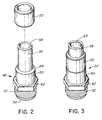
- the connector bushing 22 has an elongated main body 48 and a cylindrical outer sleeve 50.
- the main body 48 of the connector bushing 22 has a threaded cylindrical portion 52 extending from one end 54, a nonthreaded cylindrical portion 56 extending from the other end 58, and an intermediate portion 60 with a hexagonal flange 62 extending outwardly between the threaded and nonthreaded cylindrical portions 52, 56 and a central bore 63 through which the melt passage 10 extends.
- the cylindrical outer sleeve 50 fits around the nonthreaded cylindrical portion 56 of the main body 48 and abuts against a circular shoulder 64 formed by the intermediate portion 60 of the main body 48.
- the cylindrical outer sleeve 50 is shorter than the nonthreaded cylindrical portion 56 of the main body 48 and is formed of a material such as copper or a copper alloy having a higher coefficient of expansion higher than that of the main body which is formed of a high strength material such as steel.
- the cylindrical outer sleeve 50 is mounted securely in place around the nonthreaded cylindrical portion 56 of the main body 48 by first cooling the main body 48 in dry ice and then slipping the cylindrical outer sleeve 50 into place around the nonthreaded cylindrical portion 56.
- the connector bushing 22 is mounted in place with the threaded cylindrical portion 52 of the main body 48 screwed tightly into place in a threaded cylindrical opening 66 in the nozzle manifold 14 and the nonthreaded cylindrical portion 56 of the main body 48 with the surrounding outer sleeve 50 fitting in a matching nonthreaded opening 68 in the central manifold 12.
- the connector bushings 22 can be reversed with the threaded cylindrical openings 66 in the central manifold 12 and the nonthreaded opening 68 in the nozzle manifolds 14.
- the nonthreaded end 58 of the main body 48 of the connector bushing 22 abuts against a circular shoulder 70 at the inner end 72 of the nonthreaded opening 68 in the central manifold 12.
- nozzle manifolds 14 extending in opposite directions from the central manifold 12 are mounted in the mold 20 as shown in Figure 1.
- the mold 20 is cooled in a conventional manner by pumping cooling water through the cooling conduits 38. Electrical power is applied to the heating elements 34, 36 to heat the melt distribution manifolds 12, 14 and the connector bushings 22 to a desired operating temperature. As they expand, the nonthreaded end 58 of the main body 48 of each connector bushing 22 pushes against the circular shoulder 70 at the inner end 72 of the nonthreaded opening 68 in which it is received.
- each connector bushing is made of a high strength material such as steel to avoid deformation due to the very high forces generated by this thermal expansion. Also, as the central manifold 12 and the connector bushings 22 are heated, the outer sleeve 50 expands sufficiently to provide a seal against melt leakage through or around the connector bushings 22.
- each outer sleeve 50 is made of copper which has a coefficient of expansion sufficiently greater than that of the steel of which the main body 48 of the connector bushing 22 and the surrounding central manifold 12 are made to allow the nonthreaded portion 56 of the connector bushing 22 with the outer sleeve 50 mounted around it to be inserted into the nonthreaded opening 68 in the central manifold before heating and have the outer sleeve 50 expand sufficiently during heating to the operating temperature to form the melt leakage seal. Pressurized melt from the molding machine (not shown) then flows through the melt passage 10 to fill the cavities 18 according to a conventional injection cycle.
Landscapes
- Engineering & Computer Science (AREA)
- Manufacturing & Machinery (AREA)
- Mechanical Engineering (AREA)
- Injection Moulding Of Plastics Or The Like (AREA)
- Moulds For Moulding Plastics Or The Like (AREA)
- Manufacturing Of Electrical Connectors (AREA)
Applications Claiming Priority (2)
| Application Number | Priority Date | Filing Date | Title |
|---|---|---|---|
| CA2205978 | 1997-05-23 | ||
| CA002205978A CA2205978C (fr) | 1997-05-23 | 1997-05-23 | Manchon de raccordement de collecteurs de moulage par injection |
Publications (2)
| Publication Number | Publication Date |
|---|---|
| EP0879689A1 true EP0879689A1 (fr) | 1998-11-25 |
| EP0879689B1 EP0879689B1 (fr) | 2002-12-11 |
Family
ID=4160717
Family Applications (1)
| Application Number | Title | Priority Date | Filing Date |
|---|---|---|---|
| EP98107135A Expired - Lifetime EP0879689B1 (fr) | 1997-05-23 | 1998-04-20 | Manchon de raccordement pour distributeurs de moulage par injection |
Country Status (7)
| Country | Link |
|---|---|
| US (1) | US5792493A (fr) |
| EP (1) | EP0879689B1 (fr) |
| JP (1) | JPH10329175A (fr) |
| AT (1) | ATE229420T1 (fr) |
| CA (1) | CA2205978C (fr) |
| DE (1) | DE69810004T2 (fr) |
| ES (1) | ES2189030T3 (fr) |
Cited By (1)
| Publication number | Priority date | Publication date | Assignee | Title |
|---|---|---|---|---|
| NL1025041C2 (nl) * | 2003-12-17 | 2005-02-08 | S P G Promatrix B V | Hot-runnerstelsel. |
Families Citing this family (19)
| Publication number | Priority date | Publication date | Assignee | Title |
|---|---|---|---|---|
| DE19821406A1 (de) * | 1998-05-13 | 1999-11-18 | Lurgi Zimmer Ag | Abdichtungselement für Schmelzekanäle |
| NL1010869C2 (nl) * | 1998-12-22 | 2000-06-30 | Axxicon Moulds Eindhoven Bv | Meervoudige spuitgieteenheid. |
| EP1220740A1 (fr) * | 1999-10-14 | 2002-07-10 | Siemens Canada limited | Garniture d'etancheite de fermeture d'alimentation destinee a une presse pour matieres plastiques |
| DE19956554A1 (de) * | 1999-11-24 | 2001-05-31 | Mold & Hotrunner Technology Gm | Heißkanal-Verteiler-System |
| DE60011679T2 (de) * | 2000-01-24 | 2005-07-07 | The Cavist Corp., Reno | Geraet zum giessen von heissklebern |
| WO2001096060A2 (fr) * | 2000-06-16 | 2001-12-20 | Mold-Masters Limited | Procede de fabrication et d'assemblage rapides de systemes de canaux chauffants |
| US6675055B1 (en) * | 2000-06-16 | 2004-01-06 | Mold Masters Ltd. | Method and apparatus for an automated injection molding configuring and manufacturing system |
| US6821110B2 (en) * | 2002-07-23 | 2004-11-23 | The Cavist Corporation | Apparatus for molding with hot melt adhesives |
| EP1961548B1 (fr) * | 2003-04-07 | 2010-02-24 | Mold-Masters (2007) Limited | Buse à canaux chauffants avec scellement de fusion |
| US7125246B2 (en) * | 2003-10-08 | 2006-10-24 | Mold Hotrunner Solutions Inc. | Hot runner for molding small plastic articles |
| ITTO20040423A1 (it) * | 2004-06-23 | 2004-09-23 | Thermoplay Spa | Piastra di distribuzione per uno stampo per lo stampaggio ad iniezione di materiali plastici. |
| CA2542374A1 (fr) * | 2005-04-07 | 2006-10-07 | Mold-Masters Limited | Distributeur configurable |
| US7874833B2 (en) * | 2009-05-03 | 2011-01-25 | Mold-Masters (2007) Limited | Injection molding runner apparatus having pressure seal |
| CN102470589A (zh) * | 2009-07-17 | 2012-05-23 | 赫斯基注塑系统有限公司 | 模块化分流板系统 |
| DE112012003830T5 (de) | 2011-09-14 | 2014-08-07 | The Cavist Corp. | Formungsgerät |
| KR101452133B1 (ko) * | 2013-09-09 | 2014-10-16 | 김혁중 | 열팽창 보상기구가 구비된 핫런너 장치 |
| US9272455B2 (en) * | 2014-04-30 | 2016-03-01 | Mold-Masters (2007) Limited | Hot runner system sealing arrangement |
| JP7095484B2 (ja) * | 2018-08-21 | 2022-07-05 | トヨタ自動車株式会社 | ホットランナー装置 |
| CN109374024B (zh) * | 2018-11-05 | 2019-12-27 | 四川大学 | 一种具有凹坑结构的压阻式电子皮肤及其制备方法 |
Citations (3)
| Publication number | Priority date | Publication date | Assignee | Title |
|---|---|---|---|---|
| US4219323A (en) * | 1979-05-09 | 1980-08-26 | The Broadway Companies, Inc. | Self-compensating hot manifold link |
| DE4320584A1 (de) * | 1993-06-22 | 1995-01-05 | Wolff Hans Martin | Heißkanalverteiler |
| EP0816045A1 (fr) * | 1996-07-05 | 1998-01-07 | Jobst Ulrich Gellert | Distributeurs de moulage par injection avec manchon de raccordement pour matière fondue |
Family Cites Families (1)
| Publication number | Priority date | Publication date | Assignee | Title |
|---|---|---|---|---|
| CA1239515A (fr) * | 1985-09-13 | 1988-07-26 | Jobst U. Gellert | Systeme collecteur pour moulage par injection a repartiteur d'uniformisation du debit aux creux |
-
1997
- 1997-05-23 CA CA002205978A patent/CA2205978C/fr not_active Expired - Fee Related
- 1997-06-09 US US08/872,005 patent/US5792493A/en not_active Expired - Lifetime
-
1998
- 1998-04-20 ES ES98107135T patent/ES2189030T3/es not_active Expired - Lifetime
- 1998-04-20 AT AT98107135T patent/ATE229420T1/de not_active IP Right Cessation
- 1998-04-20 DE DE69810004T patent/DE69810004T2/de not_active Expired - Lifetime
- 1998-04-20 EP EP98107135A patent/EP0879689B1/fr not_active Expired - Lifetime
- 1998-05-12 JP JP10128902A patent/JPH10329175A/ja active Pending
Patent Citations (3)
| Publication number | Priority date | Publication date | Assignee | Title |
|---|---|---|---|---|
| US4219323A (en) * | 1979-05-09 | 1980-08-26 | The Broadway Companies, Inc. | Self-compensating hot manifold link |
| DE4320584A1 (de) * | 1993-06-22 | 1995-01-05 | Wolff Hans Martin | Heißkanalverteiler |
| EP0816045A1 (fr) * | 1996-07-05 | 1998-01-07 | Jobst Ulrich Gellert | Distributeurs de moulage par injection avec manchon de raccordement pour matière fondue |
Cited By (2)
| Publication number | Priority date | Publication date | Assignee | Title |
|---|---|---|---|---|
| NL1025041C2 (nl) * | 2003-12-17 | 2005-02-08 | S P G Promatrix B V | Hot-runnerstelsel. |
| WO2005058577A1 (fr) * | 2003-12-17 | 2005-06-30 | S.P.G. Promatrix B.V. | Systeme de canaux chauffants |
Also Published As
| Publication number | Publication date |
|---|---|
| DE69810004T2 (de) | 2003-04-17 |
| DE69810004D1 (de) | 2003-01-23 |
| JPH10329175A (ja) | 1998-12-15 |
| EP0879689B1 (fr) | 2002-12-11 |
| CA2205978A1 (fr) | 1998-11-23 |
| ES2189030T3 (es) | 2003-07-01 |
| CA2205978C (fr) | 2005-01-18 |
| US5792493A (en) | 1998-08-11 |
| ATE229420T1 (de) | 2002-12-15 |
Similar Documents
| Publication | Publication Date | Title |
|---|---|---|
| CA2205978C (fr) | Manchon de raccordement de collecteurs de moulage par injection | |
| US6176700B1 (en) | Injection molding cooled cavity insert | |
| US4892474A (en) | Profiled plate heaters for injection molding nozzles | |
| CA2099334C (fr) | Insert de moulage par injection a orifice d'admission et cheville d'alignement | |
| EP0816046B1 (fr) | Distributeurs à buse chauffés dans un plan commun interconnectés par des distributeurs de connexion | |
| US6095790A (en) | Injection molding cylindrical manifold insert and method | |
| US5591465A (en) | Side gated injection molding apparatus with radially mounted gate inserts | |
| EP0468484B1 (fr) | Dispositif de fixation de douille refroidie pour une buse chauffée de moulage par injection | |
| EP1170111A1 (fr) | Dispositif de moulage par injection | |
| CA2047461A1 (fr) | Distributeur de moulage par injection avec insertions amovibles | |
| JP3199911B2 (ja) | 射出成形機のシート及びシール挿入体 | |
| US5720995A (en) | Injection molding manifolds with melt connector bushing | |
| US5507636A (en) | Injection holding heated nozzle with protective tubes | |
| US5705202A (en) | Four heated nozzle manifolds interconnected in a common plane | |
| EP0743158B1 (fr) | Joint d'entrée d'injection latérale chaud avec rebord circonférentiel | |
| CA2082700A1 (fr) | Torpille de machine a mouler par injection avec buse a orifice oblique | |
| EP0638406B1 (fr) | Buse d'injection avec un élément de thermocouple | |
| EP0633118B1 (fr) | Joint en deux pièces pour buse de moulage par injection | |
| US5980236A (en) | Injection molding apparatus having nozzles with elongated mounting flanges | |
| CA2250598A1 (fr) | Appareil pour localiser et sceller une buse de moulage par injection | |
| HK1023964A (en) | Injection molding apparatus having nozzles with elongated mounting flanges |
Legal Events
| Date | Code | Title | Description |
|---|---|---|---|
| PUAI | Public reference made under article 153(3) epc to a published international application that has entered the european phase |
Free format text: ORIGINAL CODE: 0009012 |
|
| AK | Designated contracting states |
Kind code of ref document: A1 Designated state(s): AT CH DE ES FR GB IT LI LU NL PT |
|
| AX | Request for extension of the european patent |
Free format text: AL;LT;LV;MK;RO;SI |
|
| 17P | Request for examination filed |
Effective date: 19990204 |
|
| AKX | Designation fees paid |
Free format text: AT CH DE ES FR GB IT LI LU NL PT |
|
| 17Q | First examination report despatched |
Effective date: 20001109 |
|
| GRAG | Despatch of communication of intention to grant |
Free format text: ORIGINAL CODE: EPIDOS AGRA |
|
| GRAG | Despatch of communication of intention to grant |
Free format text: ORIGINAL CODE: EPIDOS AGRA |
|
| GRAH | Despatch of communication of intention to grant a patent |
Free format text: ORIGINAL CODE: EPIDOS IGRA |
|
| GRAH | Despatch of communication of intention to grant a patent |
Free format text: ORIGINAL CODE: EPIDOS IGRA |
|
| GRAA | (expected) grant |
Free format text: ORIGINAL CODE: 0009210 |
|
| AK | Designated contracting states |
Kind code of ref document: B1 Designated state(s): AT CH DE ES FR GB IT LI LU NL PT |
|
| PG25 | Lapsed in a contracting state [announced via postgrant information from national office to epo] |
Ref country code: NL Free format text: LAPSE BECAUSE OF FAILURE TO SUBMIT A TRANSLATION OF THE DESCRIPTION OR TO PAY THE FEE WITHIN THE PRESCRIBED TIME-LIMIT Effective date: 20021211 Ref country code: AT Free format text: LAPSE BECAUSE OF FAILURE TO SUBMIT A TRANSLATION OF THE DESCRIPTION OR TO PAY THE FEE WITHIN THE PRESCRIBED TIME-LIMIT Effective date: 20021211 |
|
| REF | Corresponds to: |
Ref document number: 229420 Country of ref document: AT Date of ref document: 20021215 Kind code of ref document: T |
|
| REG | Reference to a national code |
Ref country code: GB Ref legal event code: FG4D |
|
| REG | Reference to a national code |
Ref country code: CH Ref legal event code: NV Representative=s name: PATENTANWALTSBUERO JEAN HUNZIKER Ref country code: CH Ref legal event code: EP |
|
| REF | Corresponds to: |
Ref document number: 69810004 Country of ref document: DE Date of ref document: 20030123 |
|
| PG25 | Lapsed in a contracting state [announced via postgrant information from national office to epo] |
Ref country code: PT Free format text: LAPSE BECAUSE OF FAILURE TO SUBMIT A TRANSLATION OF THE DESCRIPTION OR TO PAY THE FEE WITHIN THE PRESCRIBED TIME-LIMIT Effective date: 20030311 |
|
| PG25 | Lapsed in a contracting state [announced via postgrant information from national office to epo] |
Ref country code: GB Free format text: LAPSE BECAUSE OF NON-PAYMENT OF DUE FEES Effective date: 20030420 |
|
| NLV1 | Nl: lapsed or annulled due to failure to fulfill the requirements of art. 29p and 29m of the patents act | ||
| REG | Reference to a national code |
Ref country code: ES Ref legal event code: FG2A Ref document number: 2189030 Country of ref document: ES Kind code of ref document: T3 |
|
| ET | Fr: translation filed | ||
| PLBE | No opposition filed within time limit |
Free format text: ORIGINAL CODE: 0009261 |
|
| STAA | Information on the status of an ep patent application or granted ep patent |
Free format text: STATUS: NO OPPOSITION FILED WITHIN TIME LIMIT |
|
| 26N | No opposition filed |
Effective date: 20030912 |
|
| GBPC | Gb: european patent ceased through non-payment of renewal fee |
Effective date: 20030420 |
|
| PGFP | Annual fee paid to national office [announced via postgrant information from national office to epo] |
Ref country code: CH Payment date: 20040325 Year of fee payment: 7 |
|
| PGFP | Annual fee paid to national office [announced via postgrant information from national office to epo] |
Ref country code: ES Payment date: 20040413 Year of fee payment: 7 |
|
| PGFP | Annual fee paid to national office [announced via postgrant information from national office to epo] |
Ref country code: FR Payment date: 20040427 Year of fee payment: 7 |
|
| PG25 | Lapsed in a contracting state [announced via postgrant information from national office to epo] |
Ref country code: ES Free format text: LAPSE BECAUSE OF NON-PAYMENT OF DUE FEES Effective date: 20050421 |
|
| PG25 | Lapsed in a contracting state [announced via postgrant information from national office to epo] |
Ref country code: LI Free format text: LAPSE BECAUSE OF NON-PAYMENT OF DUE FEES Effective date: 20050430 Ref country code: CH Free format text: LAPSE BECAUSE OF NON-PAYMENT OF DUE FEES Effective date: 20050430 |
|
| REG | Reference to a national code |
Ref country code: CH Ref legal event code: PL |
|
| PG25 | Lapsed in a contracting state [announced via postgrant information from national office to epo] |
Ref country code: FR Free format text: LAPSE BECAUSE OF NON-PAYMENT OF DUE FEES Effective date: 20051230 |
|
| REG | Reference to a national code |
Ref country code: FR Ref legal event code: ST Effective date: 20051230 |
|
| REG | Reference to a national code |
Ref country code: ES Ref legal event code: FD2A Effective date: 20050421 |
|
| PGFP | Annual fee paid to national office [announced via postgrant information from national office to epo] |
Ref country code: LU Payment date: 20090330 Year of fee payment: 12 |
|
| PGFP | Annual fee paid to national office [announced via postgrant information from national office to epo] |
Ref country code: IT Payment date: 20090401 Year of fee payment: 12 |
|
| PG25 | Lapsed in a contracting state [announced via postgrant information from national office to epo] |
Ref country code: IT Free format text: LAPSE BECAUSE OF NON-PAYMENT OF DUE FEES Effective date: 20100420 |
|
| PG25 | Lapsed in a contracting state [announced via postgrant information from national office to epo] |
Ref country code: LU Free format text: LAPSE BECAUSE OF NON-PAYMENT OF DUE FEES Effective date: 20100420 |
|
| PGFP | Annual fee paid to national office [announced via postgrant information from national office to epo] |
Ref country code: DE Payment date: 20170321 Year of fee payment: 20 |
|
| REG | Reference to a national code |
Ref country code: DE Ref legal event code: R071 Ref document number: 69810004 Country of ref document: DE |