EP0879753A2 - Fahrzeug mit hydraulischem Einzelradantrieb - Google Patents
Fahrzeug mit hydraulischem Einzelradantrieb Download PDFInfo
- Publication number
- EP0879753A2 EP0879753A2 EP98109337A EP98109337A EP0879753A2 EP 0879753 A2 EP0879753 A2 EP 0879753A2 EP 98109337 A EP98109337 A EP 98109337A EP 98109337 A EP98109337 A EP 98109337A EP 0879753 A2 EP0879753 A2 EP 0879753A2
- Authority
- EP
- European Patent Office
- Prior art keywords
- rotary valve
- cross
- bores
- hydraulic
- housing
- Prior art date
- Legal status (The legal status is an assumption and is not a legal conclusion. Google has not performed a legal analysis and makes no representation as to the accuracy of the status listed.)
- Granted
Links
Images


Classifications
-
- B—PERFORMING OPERATIONS; TRANSPORTING
- B62—LAND VEHICLES FOR TRAVELLING OTHERWISE THAN ON RAILS
- B62D—MOTOR VEHICLES; TRAILERS
- B62D11/00—Steering non-deflectable wheels; Steering endless tracks or the like
- B62D11/02—Steering non-deflectable wheels; Steering endless tracks or the like by differentially driving ground-engaging elements on opposite vehicle sides
- B62D11/06—Steering non-deflectable wheels; Steering endless tracks or the like by differentially driving ground-engaging elements on opposite vehicle sides by means of a single main power source
- B62D11/10—Steering non-deflectable wheels; Steering endless tracks or the like by differentially driving ground-engaging elements on opposite vehicle sides by means of a single main power source using gearings with differential power outputs on opposite sides, e.g. twin-differential or epicyclic gears
- B62D11/14—Steering non-deflectable wheels; Steering endless tracks or the like by differentially driving ground-engaging elements on opposite vehicle sides by means of a single main power source using gearings with differential power outputs on opposite sides, e.g. twin-differential or epicyclic gears differential power outputs being effected by additional power supply to one side, e.g. power originating from secondary power source
- B62D11/18—Steering non-deflectable wheels; Steering endless tracks or the like by differentially driving ground-engaging elements on opposite vehicle sides by means of a single main power source using gearings with differential power outputs on opposite sides, e.g. twin-differential or epicyclic gears differential power outputs being effected by additional power supply to one side, e.g. power originating from secondary power source the additional power supply being supplied hydraulically
- B62D11/183—Control systems therefor
-
- B—PERFORMING OPERATIONS; TRANSPORTING
- B62—LAND VEHICLES FOR TRAVELLING OTHERWISE THAN ON RAILS
- B62D—MOTOR VEHICLES; TRAILERS
- B62D11/00—Steering non-deflectable wheels; Steering endless tracks or the like
- B62D11/02—Steering non-deflectable wheels; Steering endless tracks or the like by differentially driving ground-engaging elements on opposite vehicle sides
- B62D11/06—Steering non-deflectable wheels; Steering endless tracks or the like by differentially driving ground-engaging elements on opposite vehicle sides by means of a single main power source
- B62D11/10—Steering non-deflectable wheels; Steering endless tracks or the like by differentially driving ground-engaging elements on opposite vehicle sides by means of a single main power source using gearings with differential power outputs on opposite sides, e.g. twin-differential or epicyclic gears
-
- F—MECHANICAL ENGINEERING; LIGHTING; HEATING; WEAPONS; BLASTING
- F15—FLUID-PRESSURE ACTUATORS; HYDRAULICS OR PNEUMATICS IN GENERAL
- F15B—SYSTEMS ACTING BY MEANS OF FLUIDS IN GENERAL; FLUID-PRESSURE ACTUATORS, e.g. SERVOMOTORS; DETAILS OF FLUID-PRESSURE SYSTEMS, NOT OTHERWISE PROVIDED FOR
- F15B13/00—Details of servomotor systems ; Valves for servomotor systems
- F15B13/02—Fluid distribution or supply devices characterised by their adaptation to the control of servomotors
- F15B13/06—Fluid distribution or supply devices characterised by their adaptation to the control of servomotors for use with two or more servomotors
-
- F—MECHANICAL ENGINEERING; LIGHTING; HEATING; WEAPONS; BLASTING
- F16—ENGINEERING ELEMENTS AND UNITS; GENERAL MEASURES FOR PRODUCING AND MAINTAINING EFFECTIVE FUNCTIONING OF MACHINES OR INSTALLATIONS; THERMAL INSULATION IN GENERAL
- F16K—VALVES; TAPS; COCKS; ACTUATING-FLOATS; DEVICES FOR VENTING OR AERATING
- F16K11/00—Multiple-way valves, e.g. mixing valves; Pipe fittings incorporating such valves
- F16K11/02—Multiple-way valves, e.g. mixing valves; Pipe fittings incorporating such valves with all movable sealing faces moving as one unit
- F16K11/08—Multiple-way valves, e.g. mixing valves; Pipe fittings incorporating such valves with all movable sealing faces moving as one unit comprising only taps or cocks
- F16K11/085—Multiple-way valves, e.g. mixing valves; Pipe fittings incorporating such valves with all movable sealing faces moving as one unit comprising only taps or cocks with cylindrical plug
- F16K11/0856—Multiple-way valves, e.g. mixing valves; Pipe fittings incorporating such valves with all movable sealing faces moving as one unit comprising only taps or cocks with cylindrical plug having all the connecting conduits situated in more than one plane perpendicular to the axis of the plug
Definitions
- the invention relates to a vehicle with the Features of the preamble of claim 1.
- Vehicles of this structure are primarily in the form of Single-axle vehicles in agriculture, horticulture or in the communal area for tillage, lawn, Path maintenance etc. used. They are operated by the operator directly managed and controlled.
- a known version (EP-0 397 840 B1) is on the watch this purpose a poportional divider valve that the Total current in two partial flows to the ones driving the wheels Split hydraulic motors.
- Through quantity control of the partial flows can the Aßtriebsheels with different Speed to be driven To enable cornering.
- the disadvantage here is that the hydraulic motors are connected in parallel, whereby with reduction in flow and speed one hydraulic motor flow and speed at the other Increase the hydraulic motor automatically.
- the same is the constructive and control engineering effort for the proportional division of the hydraulic flow considerably, resulting in an increased Susceptibility to failure results.
- German utility model 295 04 612.0 discloses one Serial arrangement of two hydraulic motors with a valve arrangement to control the hydraulic flow in Dependence on a swiveling movement of the handlebar across different flow rates to the direction of travel provides two hydraulic motors.
- the disadvantage here is that the individual valves separately mechanically or must be controlled electronically via additional valves, which makes handling difficult and the arrangement prone to failure makes.
- Another problem is the correct rotation Control when driving forwards and backwards of the single-axle vehicle.
- the object of the invention is for a vehicle according to the Preamble of claim 1 with series connected Hydromotors are simple, safe and easy to use low-loss control depending on the steering movement valves on the handlebar create, which eliminates the problems listed above are.
- the invention compared to known arrangements significant advantage that all steering processes (straight, left, right), which is caused by swiveling movements on the Handlebars are raised in a structurally easy way dominant rotary motion implemented on the rotary valve and the hydraulic motors alone due to its rotational position be acted upon accordingly, without any Servo valves or additional control circuits required.
- the Rotary vane four axially parallel bypass channels with check valves and in each of the two cross-sectional planes has four outgoing holes, each with are connected to a bypass channel and of which at Cornering two cross holes the connection between a bypass channel and one each Drill a hole in the housing.
- the arrangement preferably taken so that two each in one Arranged cross-sectional level, each with a bypass channel connected holes in the rotary valve are aligned and parallel to the other two.
- check valves in the both in a rotary position of the rotary valve at the same time bypass channels connected to the housing bores each have the same direction of action, so that due to the crossover connections of the hydraulic circuit the flow through the rotary valve open check valve open for an engine and for the other motor through the second closed check valve is blocked.
- the through hole is preferably in that Cross-sectional plane of the rotary valve, in which also that of Circumference of the rotary valve to the bypass channels with the Check valves leading holes are.
- the through hole connects the two hydraulic motors directly with each other, and there are two bypass channels with check valves symmetrical on both sides of the through hole arranged.
- the Possibility of using the rotary valve in the cross-sectional plane arranged channel the corresponding holes to connect a cross-sectional plane in the housing so that bypassed one of the hydraulic motors by means of a bypass can be.
- the passage in the rotary valve is preferred direct connection of the hydraulic motors via two in one Cross-sectional plane of the housing aligned holes as Circular segment-shaped recess formed on the rotary valve.
- the circular segment-shaped recess also has an advantage when reversing with two roughly parallel transverse channels in the rotary valve with oppositely acting Check valves together, the interaction of Recess and one cross channel each the possibility a bypass is justified without additional Holes are necessary.
- the Flow rate for one of the two hydraulic motors via the bypass to values between a maximum and zero be varied while the second hydraulic motor is independent of which constantly supplied with the maximum flow rate becomes.
- a direct mechanical operative connection is also preferred between the handlebar and the rotary valve.
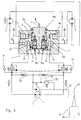
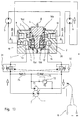
- the hydraulic motors 5, 6 are in a hydraulic circuit shown as a block diagram with a variable displacement pump 7, e.g. in axial piston design, those of the vehicle engine, not shown, e.g. an internal combustion engine, an electric motor or the like, driven becomes.
- a variable displacement pump 7 e.g. in axial piston design
- the hydraulic motors 5, 6 are provided with a rotary slide valve arrangement 1, which is described in detail below.
- the rotary valve assembly 1 has one in each constructively lowering brake 31, 32 integrated into the inlet or outlet, alternately connected via control lines stand.
- the variable displacement pump 7 is a filling pump 71 and this a setting valve 72 for the filling pump pressure assigned.
- the filling pump 71 sucks out the hydraulic oil a tank and filter, not shown, via line 73 on. You are the check valves 74, 75 for loading the suction and pressure side of the variable pump with the Filling pump pressure downstream.
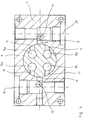
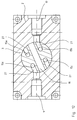
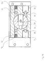
- Figures 2 and 3 show schematically the rotary valve assembly 1 with a housing 2 and one mounted therein Rotary slide valve 3.
- the housing points to two different ones Cross-sectional planes A, B holes 9, 10 or 19, 20 on, to which the hydraulic motors 5 and 6 for the left and right Wheel are connected crosswise.
- the variable displacement pump 7 is connected at the holes 19, 20 in level A.
- the rotary valve assembly 1 is constructed so that the Hydraulic motors 5 and 6 are connected in series.
- the housing For this purpose, 2 points on level B the aligned Bores 9, 10 on each of the two Hydromotors on the outlet or inlet side - depending on the direction of travel - is connected.
- the housing 2 has two this level, leading to the rotary valve 3 Bores 11, 12, each with an orthogonal for this purpose, in Fig. 2 for better clarity however, bore 13, 14 shown in the same plane in Are connected, which in turn are the connection to Manufacture variable pump 7.
- the rotary valve 3 assigns four its axis of rotation parallel, symmetrically arranged Bypass channels 15, each having a check valve 16th (Fig. 1 and 7) record. It also has four holes 17 in the cross-sectional plane A and bores 27 in the Cross-sectional plane B on the corresponding position of the rotary valve 3, the bypass channels 15 with the radial bores of the housing 2 on the cross-sectional planes A or B connect. On both cross-sectional levels A, B align two of the bores 17, 27 of the rotary valve and run parallel to the other two. On the Cross-sectional plane B also has the rotary valve 3 central through hole 18 in the middle position of the rotary valve 3 when driving straight ahead the radial holes 9, 10 connects directly in the housing 2 (FIG. 1, 2, 3, 5).
- Figures 1 to 5 show the rotary valve 3 in its Middle position when driving straight ahead, in which the Hydraulic oil directly through the holes 13 and 19 Hydraulic motor 5, which drives the left wheel, flows in and then through the hole 10 in the housing 2, the through hole 18 in the rotary valve and the bore 9 in the housing second, series-connected hydraulic motor 6 runs to then back through the holes 20 and 14 to the variable displacement pump 7 to arrive.
- the arranged in the rotary valve Bypass channels 15 with the check valves 16 are at Straight-ahead driving is not affected, as with reference to Fig. 1 already indicated and otherwise from FIGS. 4 and 5 evident. Whether the vehicle is moving forward or backward moves, depends only on the delivery direction of the variable pump that is switched by the driver. When reversing the hydraulic fluid takes the opposite way, runs So over the bore 14 to the rotary valve and the Hole 13 from.
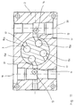
- Figures 6 to 9 show the operation of a Turning clockwise (right turn when driving straight ahead).
- the handlebar 8 By swiveling the handlebar 8 to the left the rotary valve 3 from its central position clockwise rotated (Fig. 8, 9 and 10).
- the control channels 15a and 15c with the valves 16a and 16c protrude their respective bores 17, 27 with the radial bores 9, 10, 19, 20 in the housing 2 in connection, to which in turn the hydraulic motors are connected.
- the cross each arranged, only when cornering (clockwise) check valves 16a and 16c taking effect have the same direction of action.
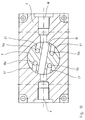
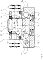
- the second embodiment shown in FIG. The invention largely shows a rotary slide valve arrangement 1 analogous to the first embodiment shown in FIG. 2. Corresponding components of both embodiments are provided with the same reference numerals.
- variable displacement pump In the embodiment shown in FIG a representation of the variable displacement pump and its control as well as the representation of the hydraulic motors.
- the rotary valve assembly has a housing 2 and a rotary valve mounted in this 3 on.
- the arrangement shows two cross-sectional levels A and B with provided in these cross-sectional planes Bores in the housing that extend to the edge of the Rotary valve 3 are sufficient.
- In each cross-sectional plane A and B are two on each side of the rotary valve 3 parallel bores 9, 9a, 10, 10a, 11, 11a, 12, 12a provided (Fig. 15, 16).
- the two above each other arranged holes in the two cross-sectional planes A and B are over four parallel to the axis of rotation of the rotary valve 3 arranged vertical bores 30, 31, 32, 33 connected with each other.
- each cross-sectional plane A and B are two 9, 10 and 11, 12 respectively Completion of the housing 2 open and form on their respective Cross-sectional level the inlets and outlets to the Hydraulic motors, the corresponding bores 9, 10 and 11, 12 of each cross-sectional plane are aligned.
- the others four holes 9a, 10a and 11a, 12a extend from the circumference of the rotary valve 3 not to the end of the housing 2. They form together with the vertical bores 30 to 33 independent of the flow path via the hydraulic motors Hydraulic connections between the two cross-sectional levels A and B. As can be seen from FIGS.
- cross-sectional plane 15 and 16 are the cross holes in each cross-sectional plane so arranged that through the axially parallel vertical bores one each until the end of the housing 2 reaching bore of a cross-sectional plane with a not to the edge of the cross hole of the others Cross-sectional level is connected.
- the vertical bores 30 and 31 are up to the connections 19 and 20 to the variable pump, not shown continued while the vertical bores 32 and 33 only a connection between the cross-sectional levels A and B produce.
- 15 further shows the design of the rotary valve 3 in the cross-sectional plane A.
- the rotary valve 3 has in this level, a central through channel 34 with a Check valve 35 on.
- the channel 34 is arranged that he turns each other diagonally when turning the rotary valve opposite bores 11a and 12 or 11 and 12a connects.
- 15 is the rotary valve 3 in a passive position for cross-sectional plane A.
- Fig. 16 shows the formation of the rotary valve 3 in the Cross-sectional plane B.
- the rotary valve 3 points in this Level a circular segment-shaped recess 36 and two approximately parallel bores 37 and 40 with check valves 38 and 39 based on the circumference of the rotary valve 3 up to the circular segment-shaped recess 36 extend. 16, the two are in the cross-sectional plane B aligned to the hydraulic motors Bores 9 and 10 connected via the recess 36.
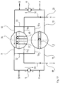
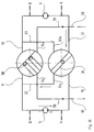
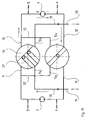
- FIGS. 17, 18 and 19 show the flow of hydraulic fluid through the hydraulic motors 5, 6 and the rotary valve assembly, the Holes only as schematic connections of their Inlets and outlets to those shown in cross section Levels A and B of the rotary valve are shown.
- Fig. 19 shows a reverse turn, the inflow the hydraulic fluid through a change on the part of the driver via the connection 19.
- the hydraulic motor 5 is in this operating position because of the missing connection blocked at hole 9 on the rotary valve.
- Of the Hydraulic flow reaches the through the vertical bore 30 Bore 9a in the cross-sectional plane B and is over the Channel 37 and the recess 36 in the rotary valve to the Bore 10 out. From the return takes place via the hydraulic motor 6 to the bore 20.
- stepless Regulation of a hydraulic motor between zero and one Maximum possible by turning the rotary valve 3 into one position is rotated in which both the recess 36 in the cross-sectional plane B as well as the through hole 34 in the cross-sectional plane A in an active position and depending on the angle of rotation of the slide forward a partial flow of the hydraulic fluid which is a bypass at least for a partial flow trains.
- Balls 23 for mounting the rotary valve in the housing serve, which are inserted in an annular groove 24, which by semicircular ring grooves at the same height in the Rotary valve and the housing are formed (Fig. 3 and 7).
- the seal of the rotary valve 3 in the housing 2 takes place by means of the O-rings 21, 22.
Landscapes
- Engineering & Computer Science (AREA)
- Mechanical Engineering (AREA)
- General Engineering & Computer Science (AREA)
- Chemical & Material Sciences (AREA)
- Combustion & Propulsion (AREA)
- Transportation (AREA)
- Fluid Mechanics (AREA)
- Automation & Control Theory (AREA)
- Physics & Mathematics (AREA)
- Control Of Fluid Gearings (AREA)
- Motor Power Transmission Devices (AREA)
- Arrangement And Driving Of Transmission Devices (AREA)
- Arrangement Or Mounting Of Propulsion Units For Vehicles (AREA)
Abstract
Description
- die Ventilanordnung eine Drehschieberanordnung mit einem Gehäuse und einem darin gelagerten Drehschieber ist,
- das Gehäuse in zwei verschiedenen Querschnittsebenen jeweils beiderseits des Drehschiebers angeordnete Bohrungen aufweist, die für beide Ebenen mit den Hydromotoren und auf zumindest einer Ebene mit der Verstellpumpe verbunden sind, wobei in der Mittelstellung des Drehschiebers für die Geradeausfahrt die beiden Hydromotoren durch einen in einer Ebene vorgesehenen Durchgang direkt verbunden sind,
- im Drehschieber Kanäle mit Rückschlagventilen angeordnet sind, die beim Verdrehen des Drehschiebers aus der Mittelstellung für die Kurvenfahrt die die Bohrungen in beiden Querschnittsebenen verbinden und dabei einen Bypass zur Reudzierung der Durchflußmenge an dem Hydromotor des Kurveninnenrades bilden, wobei die Durchflußmenge in Abhängigkeit vom Drehwinkel gesteuert wird, während die Durchflußmenge an dem Hydromotor des Kurvenaußenrades konstant bleibt.
- in jeder Querschnittsebene des Drehschiebers zumindest ein Kanal quer zur Achse des Drehschiebers angeordnet ist,
- in jeder Querschnittsebene beiderseits des Drehschiebers jeweils zwei Bohrungen angeordnet sind, die zum Umfang des Drehschiebers reichen und die mit den jeweils auf der anderen Drehschieberseite angeordneten Bohrungen in der gleichen Querschnittsebene weitgehend fluchten und von denen jeweils eine Bohrung mit einem Hydromotor verbunden ist,
- die Bohrungen in beiden Querschnittsebenen durch vertikale Bohrungen im Gehäuse (2) weitgehend parallel zur Drehschieberachse verbunden sind,
- zwei Vertikalbohrungen zur Verstellpumpe weitergeführt sind,
- durch den zumindest einen Kanal in jeder Querschnittsebene des Drehschiebers die jeweils überkreuz angeordneten Bohrungen in einer Querschnittsebene zu beiden Seiten des Drehschiebers in dessen aktiver Position verbunden sind.
- Fig. 1
- ein Schaltschema des Hydraulikkreislaufs zum Antrieb eines Fahrzeugs mit hydraulischem Einzelradantrieb;
- Fig. 2
- einen schematischen Längsschnitt der Drehschieberanordnung mit einem Schaltschema in der Position Geradeausfahrt (vorwärts);
- Fig. 3
- einen detaillierten Längsschnitt der Drehschieberanordnung bei Geradeausfahrt;
- Fig. 4
- einen Querschnitt IV-IV gemäß Fig. 3 (Radialebene A);
- Fig. 5
- einen Querschnitt V-V gemäß Fig. 3; (Radialebene B);
- Fig. 6
- eine der Fig. 2 entsprechende Darstellung bei Vorwärts-Kurvenfahrt im Uhrzeigersinn (Rechtskurve);
- Fig. 7
- einen Längsschnitt der Drehschieberanordnung ähnlich Fig. 3 bei Kurvenfahrt im Uhrzeigersinn (Rechtskurve);
- Fig. 8
- einen Schnitt VIII-VIII gemäß Fig. 7 (Radialebene A);
- Fig. 9
- einen Schnitt IX-IX gemäß Fig. 7 (Radialebene B);
- Fig. 10
- einen der Fig. 9 entsprechenden Schnitt (Radialebene B) in einer Zwischenstellung bei Kurvenfahrt im Uhrzeigersinn (Rechtskurve);
- Fig. 11
- einen der Fig. 8 entsprechenden Schnitt (Radialebene A) bei Kurvenfahrt im Gegenuhrzeigersinn (Linkskurve);
- Fig. 12
- einen der Fig. 9 entsprechenden Schnitt (Radialebene B) bei Kurvenfahrt im Gegenuhrzeigersinn (Linkskurve);
- Fig. 13
- ein der Fig. 2 entsprechendes Schaltschema bei Kurvenfahrt im Gegenuhrzeigersinn (Linkskurve);
- Fig. 14
- eine Drehschieberanordnung einer zweiten Ausführungsform im Längsschnitt;
- Fig. 15
- einen Querschnitt XV-XV gemäß Fig. 14;
- Fig. 16
- einen Querschnitt XVI-XVI gemäß Fig. 14;
- Fig. 17
- eine schematische Darstellung beider Wirkebenen des Drehschiebers sowie deren Zusammenwirken mit den Hydromotoren bei Geradeausfahrt gemäß der zweiten Ausführungsform;
- Fig. 18
- eine der Fig. 17 entsprechende Darstellung bei einer Vorwärtskurvenfahrt und
- Fig. 19
- eine der Fig. 17 entsprechende Darstellung bei einer Rückwärtskurvenfahrt.
Claims (12)
- Fahrzeug mit wenigstens einer lenkbaren Antriebsachse mit hydraulischem Einzelradantrieb, einem geschlossenen Hydraulikkreislauf mit einer Verstellpumpe (7) zur Förderung der Hydraulikflüssigkeit in beiden die Fahrtrichtung bestimmenden Richtungen, zwei seriell geschalteten, den Antrieb bildenden Hydromotoren (5, 6) und einer mit einem Lenkholm (8) des Fahrzeugs betätigbaren Ventilanordnung zur Beaufschlagung der beiden Hydromotoren (5, 6), dadurch gekennzeichnet, daßdie Ventilanordnung eine Drehschieberanordnung (1) mit einem Gehäuse (2) und einem darin gelagerten Drehschieber (3) ist,das Gehäuse in zwei verschiedenen Querschnittsebenen (A, B) jeweils beiderseits des Drehschiebers angeordnete Bohrungen aufweist, die für beide Ebenen mit den Hydromotoren (5, 6) und auf zumindest einer Ebene mit der Verstellpumpe (7) verbunden sind, wobei in der Mittelstellung des Drehschiebers (3) für die Geradeausfahrt die beiden Hydromotoren durch einen in einer Ebene vorgesehenen Durchgang (18) direkt verbunden sind,im Drehschieber (3) Kanäle (15) mit Rückschlagventilen (16) angeordnet sind, die beim Verdrehen des Drehschiebers (3) aus der Mittelstellung für die Kurvenfahrt die Bohrungen in beiden Querschnittsebenen (A, B) verbinden und dabei einen Bypass zur Reduzierung der Durchflußmenge an dem Hydromotor des Kurveninnenrades bilden, wobei die Durchflußmenge in Abhängigkeit vom Drehwinkel gesteuert wird, während die Durchflußmenge an dem Hydromotor des Kurvenaußenrades konstant bleibt.
- Fahrzeug nach Anspruch 1, dadurch gekennzeichnet, daß die Kanäle (15) parallel zu der Achse des Drehschiebers (3) angeordnet sind und in ihrer aktiven Stellung einen Bypass zwischen den auf unterschiedlichen Querschnittsebenen an einer Seite des Drehschiebers (2) angeordneten Bohrungen in dem Gehäuse bilden, wobei diese Bohrungen jeweils überkreuz an die Hydromotoren angeschlossen sind.
- Fahrzeug nach Anspruch 1 oder 2, dadurch gekennzeichnet, daß der Drehschieber vier achsparallele Bypass-Kanäle (15) mit Rückschlagventilen (16) und in jeder der beiden Querschnittsebenen (A, B) vier vom Umfang ausgehende Bohrungen (17, 27) aufweist, die mit je einem Bypass-Kanal verbunden sind und von denen bei Kurvenfahrt jeweils zwei überkreuz angeordnete Bohrungen (9, 19), (10, 20) die Verbindung zwischen einem Bypass-Kanal (15) und je einer Gehäuse-Bohrung in den beiden Querschnittsebenen herstellen.
- Fahrzeug nach Anspruch 3, dadurch gekennzeichnet, daß je zwei der in einer Querschnittsebene (A, B) angeordneten, mit je einem Bypass-Kanal (15) verbundenen Bohrungen (17, 27) im Drehschieber (3) fluchten und parallel zu den beiden anderen verlaufen.
- Fahrzeug nach einem der Ansprüche 1 bis 4, dadurch gekennzeichnet, daß die Rückschlagventile (16) in den beiden in einer Drehlage des Drehschiebers (3) gleichzeitig mit den Gehäuse-Bohrungen (9, 10, 19, 20) in Verbindung stehenden Bypass-Kanälen (15) jeweils gleiche Wirkrichtung aufweisen.
- Fahrzeug nach einem der Ansprüche 1 bis 5, dadurch gekennzeichnet, daß der Drehschieber (3) für die Geradeausfahrt als Durchgang eine zentrale Durchgangsbohrung (18) aufweist, die in der Mittelstellung des Drehschiebers (3) die beiden in einer Querschnittsebene (B) liegenden Gehäuse-Bohrungen (9, 10) direkt verbindet und zu deren beiden Seiten jeweils zwei der vier Bypass-Kanäle (15) angeordnet sind.
- Fahrzeug nach Anspruch 1, dadurch gekennzeichnet, daßin jeder Querschnittsebene (A, B) des Drehschiebers (3) zumindest ein Kanal quer zur Achse des Drehschiebers angeordnet ist,in jeder Querschnittsebene (A, B) beiderseits des Drehschiebers (3) jeweils zwei Bohrungen (11, 11a, 12, 12a bzw. 9, 9a, 10, 10a) angeordnet sind, die zum Umfang des Drehschiebers reichen und die mit den jeweils auf der anderen Drehschieberseite angeordneten Bohrungen in der gleichen Querschnittsebene weitgehend fluchten und von denen jeweils eine Bohrung mit einem Hydromotor verbunden ist,die Bohrungen in beiden Querschnittsebenen (A, B) durch vertikale Bohrungen (30, 31 ,32, 33) im Gehäuse (2) weitgehend parallel zur Drehschieberachse verbunden sind,zwei Vertikalbohrungen (30, 31) Verstellpumpe (7) weitergeführt sind,durch den zumindest einen Kanal in jeder Querschnittsebene (A, B) des Drehschiebers (3) die jeweils überkreuz angeordneten Bohrungen in einer Querschnittsebene (A, B) zu beiden Seiten des Drehschiebers (3) in dessen aktiver Position verbunden sind.
- Fahrzeug nach Anspruch 1 oder 6, dadurch gekennzeichnet, daß der Durchgang (36) in dem Drehschieber (3) zur direkten Verbindung der Hydromotoren (5, 6) über zwei fluchtende Bohrungen (9, 10) in einer Querschnittsebene (B) des Gehäuses als kreissegmentförmige Aussparung am Drehschieber ausgebildet ist.
- Fahrzeug nach Anspruch 6 oder 7, dadurch gekennzeichnet, daß die kreissegmentförmige Aussparung bei Rückwärtsfahrt mit zwei in etwa parallelen Querkanälen in dem Drehschieber mit entgegengesetzt wirkenden Rückschlagventilen zusammenwirkt.
- Fahrzeug nach einem der Ansprüche 1 bis 9, dadurch gekennzeichnet, daß die Durchflußmenge für jeweils einen der beiden Hydromotoren (5, 6) stufenlos zwischen Null und einem Maximum steuerbar ist.
- Fahrzeug nach Anspruch 1, dadurch gekennzeichnet, daß der Lenkholm (8) mechanisch mit dem Drehschieber (3) wirkverbunden ist.
- Fahrzeug nach Anspruch 1, dadurch gekennzeichnet, daß die Drehschieberanordnung integrierte Senkbremsen aufweist.
Applications Claiming Priority (2)
| Application Number | Priority Date | Filing Date | Title |
|---|---|---|---|
| DE19721623 | 1997-05-23 | ||
| DE19721623A DE19721623A1 (de) | 1997-05-23 | 1997-05-23 | Fahrzeug mit hydraulischem Einzelradantrieb |
Publications (3)
| Publication Number | Publication Date |
|---|---|
| EP0879753A2 true EP0879753A2 (de) | 1998-11-25 |
| EP0879753A3 EP0879753A3 (de) | 2000-04-12 |
| EP0879753B1 EP0879753B1 (de) | 2001-12-12 |
Family
ID=7830294
Family Applications (1)
| Application Number | Title | Priority Date | Filing Date |
|---|---|---|---|
| EP98109337A Expired - Lifetime EP0879753B1 (de) | 1997-05-23 | 1998-05-22 | Fahrzeug mit hydraulischem Einzelradantrieb |
Country Status (3)
| Country | Link |
|---|---|
| EP (1) | EP0879753B1 (de) |
| AT (1) | ATE210575T1 (de) |
| DE (2) | DE19721623A1 (de) |
Cited By (3)
| Publication number | Priority date | Publication date | Assignee | Title |
|---|---|---|---|---|
| EP1209962A4 (de) * | 1999-06-14 | 2004-12-22 | Textron Inc | Zweiwege einzelpumpen, hydrostatischer antrieb für mäher |
| EP2093128A2 (de) | 2008-02-21 | 2009-08-26 | agria-Werke GmbH | Lenkvorrichtung für ein Fahrzeug mit hydraulischem Einzelradantreib, derartiges Fahrzeug und Verfahren zum lenkbaren Antrieb eines solchen Fahrzeugs |
| CN101225844B (zh) * | 2006-12-04 | 2010-12-22 | 丹科斯公司 | 用于液压致动阀的快速紧急关闭的系统和阀装置 |
Families Citing this family (1)
| Publication number | Priority date | Publication date | Assignee | Title |
|---|---|---|---|---|
| DE10025508B4 (de) * | 2000-05-23 | 2009-02-05 | Sauer-Danfoss Holding Aps | Fahrzeug-Antriebsanordnung |
Citations (1)
| Publication number | Priority date | Publication date | Assignee | Title |
|---|---|---|---|---|
| EP0397840B1 (de) | 1988-11-18 | 1994-06-22 | BUCHER GmbH Maschinenfabrik | Hydraulische schaltungsanordnung |
Family Cites Families (7)
| Publication number | Priority date | Publication date | Assignee | Title |
|---|---|---|---|---|
| DE1023342B (de) * | 1957-03-29 | 1958-01-23 | Ver Westdeutsche Waggonfab | Vorrichtung zur Steuerung des hydrostatischen Antriebes von Fahrzeugen, insbesondere von Hubstaplern |
| DE1937624A1 (de) * | 1969-07-24 | 1971-03-04 | Paul Jaeck | Hydraulische Antriebsvorrichtung fuer Kraftfahrzeuge |
| DE3241793A1 (de) * | 1982-11-11 | 1984-05-17 | Linde Ag, 6200 Wiesbaden | Steuereinrichtung fuer den antrieb eines fahrzeuges mit differenzgeschwindigkeitslenkung |
| EP0141874A1 (de) * | 1983-11-14 | 1985-05-22 | Hans Hermes Steuerungstechnik | Wegeventilvorrichtung |
| DE4108915C2 (de) * | 1991-03-19 | 2002-08-01 | Bosch Gmbh Robert | Hydraulische Einrichtung zur Druckmittelversorgung eines bevorrechtigten Primärlastkreises |
| DE9204646U1 (de) * | 1992-04-04 | 1993-08-05 | O & K Orenstein & Koppel Ag, 13581 Berlin | Hydrostatischer Fahrantrieb für Mobilfahrzeuge |
| CH689015A5 (de) * | 1994-05-27 | 1998-07-31 | Rapid Masch Fahrzeuge Ag | Verfahren zur Antriebssteuerung eines Einachstraktors. |
-
1997
- 1997-05-23 DE DE19721623A patent/DE19721623A1/de not_active Withdrawn
-
1998
- 1998-05-22 DE DE59802396T patent/DE59802396D1/de not_active Expired - Fee Related
- 1998-05-22 AT AT98109337T patent/ATE210575T1/de not_active IP Right Cessation
- 1998-05-22 EP EP98109337A patent/EP0879753B1/de not_active Expired - Lifetime
Patent Citations (1)
| Publication number | Priority date | Publication date | Assignee | Title |
|---|---|---|---|---|
| EP0397840B1 (de) | 1988-11-18 | 1994-06-22 | BUCHER GmbH Maschinenfabrik | Hydraulische schaltungsanordnung |
Cited By (5)
| Publication number | Priority date | Publication date | Assignee | Title |
|---|---|---|---|---|
| EP1209962A4 (de) * | 1999-06-14 | 2004-12-22 | Textron Inc | Zweiwege einzelpumpen, hydrostatischer antrieb für mäher |
| CN101225844B (zh) * | 2006-12-04 | 2010-12-22 | 丹科斯公司 | 用于液压致动阀的快速紧急关闭的系统和阀装置 |
| EP2093128A2 (de) | 2008-02-21 | 2009-08-26 | agria-Werke GmbH | Lenkvorrichtung für ein Fahrzeug mit hydraulischem Einzelradantreib, derartiges Fahrzeug und Verfahren zum lenkbaren Antrieb eines solchen Fahrzeugs |
| DE102008010335A1 (de) | 2008-02-21 | 2009-09-03 | Agria-Werke Gmbh | Lenkvorrichtung für ein Fahrzeug mit hydraulischem Einzelradantrieb, derartige Fahrzeuge und Verfahren zum lenkbaren Antreiben eines Fahrzeugs |
| DE102008010335B4 (de) * | 2008-02-21 | 2012-03-15 | Agria-Werke Gmbh | Lenkvorrichtung für ein Fahrzeug mit hydraulischem Einzelradantrieb, derartige Fahrzeuge und Verfahren zum lenkbaren Antreiben eines Fahrzeugs |
Also Published As
| Publication number | Publication date |
|---|---|
| DE59802396D1 (de) | 2002-01-24 |
| EP0879753B1 (de) | 2001-12-12 |
| ATE210575T1 (de) | 2001-12-15 |
| EP0879753A3 (de) | 2000-04-12 |
| DE19721623A1 (de) | 1998-11-26 |
Similar Documents
| Publication | Publication Date | Title |
|---|---|---|
| DE4090852C2 (de) | Servolenkung | |
| DE69906920T2 (de) | Getriebevorrichtung für fahrbare Maschine mit Ventil zur Kontrolle des Kurvenverhaltens | |
| DE3635162C2 (de) | ||
| DE3733102C2 (de) | ||
| DE3002598C2 (de) | ||
| DE60003345T2 (de) | Übertragungsvorrichtung für bewegliche Maschine mit mindestens zwei hintereinandergeschalteten Verdrängermotoren | |
| EP0879753B1 (de) | Fahrzeug mit hydraulischem Einzelradantrieb | |
| DE2904111C2 (de) | Hydrostatische Lenkeinrichtung | |
| EP0746492B1 (de) | Hydraulische lenkeinrichtung mit übersetzungsänderung | |
| DE3744215A1 (de) | Mehrachsgetriebenes fahrzeug | |
| DE10301752B4 (de) | Verfahren zur Bemessung eines Lenkölstromes und hydraulische Lenkeinrichtung mit Stromverstärkung | |
| DE3031230C2 (de) | Hydrostatische Hilfskraftlenkeinrichtung | |
| EP0352431A2 (de) | Steuervorrichtung zur Differenzgeschwindigkeitslenkung eines Fahrzeuges | |
| EP0839703A1 (de) | Hydraulische Lenkeinrichtung mit Übersetzungsänderung und Stromverstärkung | |
| DE19635462A1 (de) | 11lfskraftlenkung für Kraftfahrzeuge | |
| DE2749788C2 (de) | Ventil für eine hydraulische Fahrzeugknicklenkeinrichtung | |
| DE2559174A1 (de) | Steuereinrichtung fuer fahrzeug- hilfskraftlenkungen | |
| EP2093128B1 (de) | Lenkvorrichtung für ein Fahrzeug mit hydraulischem Einzelradantreib, derartiges Fahrzeug und Verfahren zum lenkbaren Antrieb eines solchen Fahrzeugs | |
| WO2000077426A1 (de) | Hydrostatischer fahrantrieb | |
| DE1942086B2 (de) | Hydrostatische Hilfskraftlenkeinrichtung, insbesondere für Kraftfahrzeuge | |
| DE19838651A1 (de) | Antriebsvorrichtung für ein Fahrzeug mit drei hydraulisch angetriebenen Radgruppen | |
| DE3124611A1 (de) | "ausgleichs- oder kompensationsvorrichtung fuer eine vorrichtung mit unter druck stehender fluessigkeit, welche zwei gegeneinander bewegliche organe aufweist und anwendungen der vorrichtung, insbesondere die anwendung bei einer servolenkung (lenkhilfe) eines fahrzeuges" | |
| EP1429954B1 (de) | Hydraulische lenkeinrichtung mit bersetzungs nderung | |
| DE102004029749A1 (de) | Verfahren zur Herstellung eines Drehschiebersteuerventils für eine hydraulische Lenkeinrichtung | |
| DE19602196A1 (de) | Hydraulisches Antriebssystem für Fahrzeuge |
Legal Events
| Date | Code | Title | Description |
|---|---|---|---|
| PUAI | Public reference made under article 153(3) epc to a published international application that has entered the european phase |
Free format text: ORIGINAL CODE: 0009012 |
|
| AK | Designated contracting states |
Kind code of ref document: A2 Designated state(s): AT CH DE FR GB IT LI |
|
| AX | Request for extension of the european patent |
Free format text: AL;LT;LV;MK;RO;SI |
|
| PUAL | Search report despatched |
Free format text: ORIGINAL CODE: 0009013 |
|
| AK | Designated contracting states |
Kind code of ref document: A3 Designated state(s): AT BE CH CY DE DK ES FI FR GB GR IE IT LI LU MC NL PT SE |
|
| AX | Request for extension of the european patent |
Free format text: AL;LT;LV;MK;RO;SI |
|
| RIC1 | Information provided on ipc code assigned before grant |
Free format text: 7B 62D 11/18 A, 7B 62D 11/06 B, 7F 15B 13/04 B, 7F 15B 13/01 B |
|
| 17P | Request for examination filed |
Effective date: 20000524 |
|
| AKX | Designation fees paid |
Free format text: AT CH DE FR GB IT LI |
|
| GRAG | Despatch of communication of intention to grant |
Free format text: ORIGINAL CODE: EPIDOS AGRA |
|
| GRAG | Despatch of communication of intention to grant |
Free format text: ORIGINAL CODE: EPIDOS AGRA |
|
| GRAH | Despatch of communication of intention to grant a patent |
Free format text: ORIGINAL CODE: EPIDOS IGRA |
|
| 17Q | First examination report despatched |
Effective date: 20010517 |
|
| GRAH | Despatch of communication of intention to grant a patent |
Free format text: ORIGINAL CODE: EPIDOS IGRA |
|
| GRAA | (expected) grant |
Free format text: ORIGINAL CODE: 0009210 |
|
| AK | Designated contracting states |
Kind code of ref document: B1 Designated state(s): AT CH DE FR GB IT LI |
|
| REF | Corresponds to: |
Ref document number: 210575 Country of ref document: AT Date of ref document: 20011215 Kind code of ref document: T |
|
| REG | Reference to a national code |
Ref country code: CH Ref legal event code: EP |
|
| REG | Reference to a national code |
Ref country code: GB Ref legal event code: IF02 |
|
| REF | Corresponds to: |
Ref document number: 59802396 Country of ref document: DE Date of ref document: 20020124 |
|
| REG | Reference to a national code |
Ref country code: CH Ref legal event code: NV Representative=s name: TROESCH SCHEIDEGGER WERNER AG |
|
| GBT | Gb: translation of ep patent filed (gb section 77(6)(a)/1977) |
Effective date: 20020226 |
|
| ET | Fr: translation filed | ||
| PLBE | No opposition filed within time limit |
Free format text: ORIGINAL CODE: 0009261 |
|
| STAA | Information on the status of an ep patent application or granted ep patent |
Free format text: STATUS: NO OPPOSITION FILED WITHIN TIME LIMIT |
|
| 26N | No opposition filed | ||
| PGFP | Annual fee paid to national office [announced via postgrant information from national office to epo] |
Ref country code: AT Payment date: 20080514 Year of fee payment: 11 |
|
| PGFP | Annual fee paid to national office [announced via postgrant information from national office to epo] |
Ref country code: IT Payment date: 20080524 Year of fee payment: 11 |
|
| PGFP | Annual fee paid to national office [announced via postgrant information from national office to epo] |
Ref country code: FR Payment date: 20080530 Year of fee payment: 11 |
|
| PGFP | Annual fee paid to national office [announced via postgrant information from national office to epo] |
Ref country code: GB Payment date: 20080423 Year of fee payment: 11 |
|
| PGFP | Annual fee paid to national office [announced via postgrant information from national office to epo] |
Ref country code: DE Payment date: 20090520 Year of fee payment: 12 |
|
| PGFP | Annual fee paid to national office [announced via postgrant information from national office to epo] |
Ref country code: CH Payment date: 20090525 Year of fee payment: 12 |
|
| GBPC | Gb: european patent ceased through non-payment of renewal fee |
Effective date: 20090522 |
|
| PG25 | Lapsed in a contracting state [announced via postgrant information from national office to epo] |
Ref country code: AT Free format text: LAPSE BECAUSE OF NON-PAYMENT OF DUE FEES Effective date: 20090522 |
|
| REG | Reference to a national code |
Ref country code: FR Ref legal event code: ST Effective date: 20100129 |
|
| PG25 | Lapsed in a contracting state [announced via postgrant information from national office to epo] |
Ref country code: FR Free format text: LAPSE BECAUSE OF NON-PAYMENT OF DUE FEES Effective date: 20090602 |
|
| PG25 | Lapsed in a contracting state [announced via postgrant information from national office to epo] |
Ref country code: GB Free format text: LAPSE BECAUSE OF NON-PAYMENT OF DUE FEES Effective date: 20090522 |
|
| REG | Reference to a national code |
Ref country code: CH Ref legal event code: PL |
|
| PG25 | Lapsed in a contracting state [announced via postgrant information from national office to epo] |
Ref country code: LI Free format text: LAPSE BECAUSE OF NON-PAYMENT OF DUE FEES Effective date: 20100531 Ref country code: CH Free format text: LAPSE BECAUSE OF NON-PAYMENT OF DUE FEES Effective date: 20100531 |
|
| PG25 | Lapsed in a contracting state [announced via postgrant information from national office to epo] |
Ref country code: IT Free format text: LAPSE BECAUSE OF NON-PAYMENT OF DUE FEES Effective date: 20090522 |
|
| PG25 | Lapsed in a contracting state [announced via postgrant information from national office to epo] |
Ref country code: DE Free format text: LAPSE BECAUSE OF NON-PAYMENT OF DUE FEES Effective date: 20101201 |