EP0879759B1 - Schubbefestigung eines Triebwerkes an einem Luftfahrzeug - Google Patents
Schubbefestigung eines Triebwerkes an einem Luftfahrzeug Download PDFInfo
- Publication number
- EP0879759B1 EP0879759B1 EP98201539A EP98201539A EP0879759B1 EP 0879759 B1 EP0879759 B1 EP 0879759B1 EP 98201539 A EP98201539 A EP 98201539A EP 98201539 A EP98201539 A EP 98201539A EP 0879759 B1 EP0879759 B1 EP 0879759B1
- Authority
- EP
- European Patent Office
- Prior art keywords
- thrust
- evener bar
- mount
- evener
- bar
- Prior art date
- Legal status (The legal status is an assumption and is not a legal conclusion. Google has not performed a legal analysis and makes no representation as to the accuracy of the status listed.)
- Expired - Lifetime
Links
Images


Classifications
-
- B—PERFORMING OPERATIONS; TRANSPORTING
- B64—AIRCRAFT; AVIATION; COSMONAUTICS
- B64D—EQUIPMENT FOR FITTING IN OR TO AIRCRAFT; FLIGHT SUITS; PARACHUTES; ARRANGEMENT OR MOUNTING OF POWER PLANTS OR PROPULSION TRANSMISSIONS IN AIRCRAFT
- B64D27/00—Arrangement or mounting of power plants in aircraft; Aircraft characterised by the type or position of power plants
- B64D27/40—Arrangements for mounting power plants in aircraft
- B64D27/406—Suspension arrangements specially adapted for supporting thrust loads, e.g. thrust links
-
- B—PERFORMING OPERATIONS; TRANSPORTING
- B64—AIRCRAFT; AVIATION; COSMONAUTICS
- B64D—EQUIPMENT FOR FITTING IN OR TO AIRCRAFT; FLIGHT SUITS; PARACHUTES; ARRANGEMENT OR MOUNTING OF POWER PLANTS OR PROPULSION TRANSMISSIONS IN AIRCRAFT
- B64D27/00—Arrangement or mounting of power plants in aircraft; Aircraft characterised by the type or position of power plants
- B64D27/02—Aircraft characterised by the type or position of power plants
- B64D27/16—Aircraft characterised by the type or position of power plants of jet type
- B64D27/18—Aircraft characterised by the type or position of power plants of jet type within, or attached to, wings
-
- B—PERFORMING OPERATIONS; TRANSPORTING
- B64—AIRCRAFT; AVIATION; COSMONAUTICS
- B64D—EQUIPMENT FOR FITTING IN OR TO AIRCRAFT; FLIGHT SUITS; PARACHUTES; ARRANGEMENT OR MOUNTING OF POWER PLANTS OR PROPULSION TRANSMISSIONS IN AIRCRAFT
- B64D27/00—Arrangement or mounting of power plants in aircraft; Aircraft characterised by the type or position of power plants
- B64D27/40—Arrangements for mounting power plants in aircraft
- B64D27/402—Arrangements for mounting power plants in aircraft comprising box like supporting frames, e.g. pylons or arrangements for embracing the power plant
-
- Y—GENERAL TAGGING OF NEW TECHNOLOGICAL DEVELOPMENTS; GENERAL TAGGING OF CROSS-SECTIONAL TECHNOLOGIES SPANNING OVER SEVERAL SECTIONS OF THE IPC; TECHNICAL SUBJECTS COVERED BY FORMER USPC CROSS-REFERENCE ART COLLECTIONS [XRACs] AND DIGESTS
- Y02—TECHNOLOGIES OR APPLICATIONS FOR MITIGATION OR ADAPTATION AGAINST CLIMATE CHANGE
- Y02T—CLIMATE CHANGE MITIGATION TECHNOLOGIES RELATED TO TRANSPORTATION
- Y02T50/00—Aeronautics or air transport
- Y02T50/40—Weight reduction
Definitions
- thrust mounts be designed in such a way as to minimize the risk of an engine loss should the thrust mount fail. It is also important that the mount be relatively easy to manufacture, install, and maintain. At times, these aspects produce incompatible design goals that are difficult to effectively reconcile.
- one current thrust mount described in the above-identified prior art document US-A-5,320,307 uses a primary pin and two catcher pins to hold an evener beam in a center clevis and two laterally spaced apart failsafe clevises of an aft engine mount.
- the primary pin is arranged in the center clevis for carrying the axial thrust force from both thrust links to the aft engine mount.
- the catcher pins are arranged with play in openings in the failsafe clevises, such that they do not carry any force during normal operations. Both catcher pins are designed to engage the respective openings if the primary pin fails or if a thrust link fails.
- This prior art design requires a wide thust mount having three clevises in order to accept three pins in a row.
- Such a mount is costly to machine since an end mill must reach a long distance into a hard material, e.g., titanium, in order to machine the open areas required to form the thrust clevises.
- This configuration also has the disadvantage of being inherently heavier because the required in-line bores limit the amount of weight-reducing pocketing that may be accomplished in the evener beam.
- the second catcher pin and the wideness of the overall mount also add weight to this particular design.
- the mount should provide adequate load bearing capability in the event of a thrust link or pin failure and should be easy to install.
- the mount should also be easy to maintain and require less custom manufacturing than current designs.
- a thrust mount for carrying axial engine loads and moments to various locations on a support structure such as a wing pylon having the features of preamble of claim 1 is characterized in that the slot of each thrust lug is closed at its forward end, each closed end defining a contact surface for engagement by the respective evener bar end during a failure condition.
- Using an evener bar end rather than a catcher pin in an alternate load path in the event of a failure results in a more efficient structure.
- the thrust mount may be connected between an engine frame and a support structure attachment fitting.
- the thrust mount is attached between a forward fan frame and an aft engine mount upper fitting.
- Thrust mounts formed in accordance with the invention can be used in various locations on an airplane (e.g., to a wing pylon, to a tail strut, etc.) as well as at various engine locations (e.g., at the forward portion of the engine or at the aft portion of the engine).
- FIGURES 1 and 2 Illustrated schematically in FIGURES 1 and 2 is an exemplary aircraft turbine jet engine 10 mounted to a support structure, such as a conventional wing pylon or strut 12.
- the engine 10 includes a fan 14 which is supported by a forward frame 16 fixedly joined to the engine 10 via an inner annulus 17, as shown in FIGURE 2.
- a forward engine mount 18 attaches a portion of the forward frame 16 to a forward location of the pylon 12.
- An aft engine mount 20 supports a rear frame 22 fixedly joined to an aft portion of the engine 10.
- the forward frame 16 and the rear frame 22 are disposed generally coaxially about the centerline axis of the engine 10.
- a thrust mount 24 formed according to the present invention is provided for carrying axial engine forces and moments to the support structure. In the preferred embodiment, the thrust mount 24 is attached to the forward frame inner annulus 17 and the aft engine mount 20.
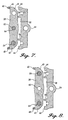
- FIGURE 3 Shown in FIGURE 3 is a perspective view of the thrust mount 24.
- a central clevis 30 extends from a forward surface 32 of a support structure attachment fitting, such as an aft engine mount upper fitting 34.
- the central clevis 30 accepts a center portion 36 of an elongated evener bar 38 and secures the evener bar therein using a rotatable connection mechanism 40.
- the mount further includes a pair of forwardly extending thrust lugs 42, each having a slot 44 therein.
- First and second evener bar ends 43, 45 are disposed in the thrust lug slots 44.
- Conventional first and second thrust links 46, 48 are provided. Each link has a first end connected to the engine frame and a second end rotatably connected to the evener bar. Under normal operating conditions, thrust loads are passed from the thrust links to the evener bar and through the rotatable connection mechanism 40 to the upper fitting 34. During a failure condition, the evener bar moves such that loads are transmitted through the thrust lug
- thrust link proximal ends 52 to evener bar 38 are pin-and-clevis joints 54 whereby each proximal end 52 is in the form of a clevis with upper and lower tines to receive the evener bar 38 between the tines. Shear pins are inserted therethrough.
- the axis of rotation between the thrust links and the evener bar is oriented generally normal to the longitudinal axis of the thrust links.
- a substantially straight tube portion 56 extends between each thrust link's proximal and distal ends.
- the desired tube portion thickness, diameter, and material composition are determined using current design practices and considerations well known to those skilled in the art.
- the upper fitting 34 includes a mounting platform 58 for attaching the aft engine mount 20 to the wing pylon 12 by conventional methods, such as using mounting bolts (not shown) extending through a number of holes in the platform 58.
- the central clevis 30 extends from the upper fitting 34 at a slight, downward angle. This angle is due to the location of the thrust link distal end connections with the forward annulus 17. In general, the exact orientation of the central clevis 30 will be a function of the thrust link forward connections. It is preferable that the connections of the thrust links 46, 48 to the evener bar 38, and the evener bar 38 to the central clevis 30, be substantially co-planar (such as is shown in FIGURE 3.)
- the rotatable connection mechanism 40 includes components located generally in the center of the central clevis.
- the preferred rotatable connection mechanism 40 is also a pin-and-clevis type connection.
- the evener bar and central clevis both include primary pin holes 62, 62' that are generally circular and are formed about an axis transverse to the plane of the evener bar 38. These holes 62, 62' are sized according to the requirements of a particular application and factors known to those skilled in the art.
- the evener bar center portion is inserted between the tines of the central clevis 30, the evener bar primary pin hole 62 aligns with the central clevis primary pin holes 62'.
- a primary pin 64 is inserted through the evener bar and central clevis primary pin holes 62, 62'.
- the primary pin 64 includes a head 66 located at one end and a threaded shank portion 68 located at the other end. When inserted in the clevis tines, the length of each pin is sufficient to allow the threaded portion 68 to extend past the tines.
- a nut 70 engages the threaded portion 68 to secure the pin in the clevis.
- Multiple bushings 72 may be used to reduce vibration and frictional wear of the evener bar and of the primary pin 64.
- the clevis tines, the bushings 72, the evener bar 38 and the pin are generally sized to fit closely together.
- the above-described primary pin arrangement is the preferred embodiment of the rotatable connection mechanism 40.
- the present invention encompasses the use of other rotatable connection mechanisms provided they allow rotation of the evener bar relative to the central clevis.
- the thrust lugs 42 also extend forward from the upper fitting forward surface 32.
- the thrust lug slots 44 are oriented in a generally upright longitudinal plane and are sized large enough so that the evener bar end surfaces during normal (unfailed) operations, do not contact any surface of the slots 44.
- the evener bar 38 has a generally constant thickness, although a designer may vary the thickness at select locations depending on the expected design stresses.
- the evener bar 38 may also be formed to include structurally reinforced portions capable of providing extra load-carrying capability and bored-out portions (such as indentation 74 shown in FIGURE 4) to lessen the overall weight of the thrust mount. The precise location and size of these alterations will depend on the particular application.
- the evener bar must be shaped and sized such that once it is connected to the upper fitting at the rotatable connection mechanism, the evener bar can pivot easily without rubbing or catching on any portion of the fitting or central clevis.
- the upper fitting includes one or more thrust stops 76 extending toward the evener bar 38 for use during a mount failure in reverse thrust. These stops are optional, depending on whether providing a failsafe thrust mount during reverse thrust is required. Should the thrust stops 76 be used, the preferred order of position between mount components is for the link-to-bar connections to be inboard, though near, their respective thrust lugs, with a single thrust stop located between the rotatable connection mechanism and each thrust link connection to the evener bar.
- the evener bar 38 is preferably positioned to leave a slight distance 78 between the evener bar aft surface and the upper fitting forward surface 32 during normal use and during a forward thrust mount failure. Otherwise, the evener bar aft surface may butt against the thrust stops 76 prior to the evener bar ends contacting their respective thrust lug slot surfaces. Such a condition is not an optimal load transmitting arrangement, since the evener bar end contacting the stop may be along the failed load path and hence potentially structurally compromised.
- the preferred distance 78 from the evener bar aft surface to the thrust stops 76 is preferably in the range of about 0.2 cm to 0.3 cm. A distance of about 0.25 cm has been found to work well for one embodiment designed for use with a CFMI 56-7 engine. To form a compact and efficient thrust mount, a designer should plan to use the smallest distance possible considering various factors, e.g., manufacturing tolerances, load deflections, thermal deflections, etc.
- thrust loads are transferred from the engine frame or fan annulus 17 to the thrusts links 46, 48, then to the evener bar 38, and finally to the upper fitting 34 via the rotatable connection mechanism 40.
- a first thrust load path exists along the first thrust link through its connection to the evener bar to the location of the central clevis, and a second thrust load path exists along the second thrust link through its connection to the evener bar to the location of the central clevis.
- Thrust loads may be directed either forwardly, as during propulsive operation of the engine, which places the thrust links 46, 48 in tension; or the thrust loads may be directed aftward, as upon deployment of the conventional thrust reversers of the engine, which places the thrust links 46, 48 in compression.
- the substantial equality of loads stemming from the thrust links 46, 48 to the evener bar 38 ensures the distance 78 between the evener bar aft surface and the upper fitting forward surface 32 and/or thrust stops. This arrangement allows the load path to pass to the upper fitting entirely through the rotatable connection mechanism 40.
- the evener bar aft surface does not contact the upper fitting forward surface 32, nor do the thrust lugs 42 carry any loads.
- failure of a thrust link load path causes the evener bar to rotate about the rotatable connection mechanism 40 until the evener bar aft surface at the unfailed evener bar end contacts its nearest reverse thrust stop 76. Failure of the rotatable connection mechanism 40 causes the entire evener bar to shift aft until its aft surface bears against both stops.
- the thrust mount of the present invention helps keep the engine attached to the airplane even during failure at any single point along the thrust mount load path, including failure at one of the thrust links, one of the link-to-mount connections, the evener bar, or the thrust mount central clevis. Locating the thrust lugs outboard of the thrust links places them in an area on the evener bar where there are no bending stresses for intact conditions. For failure conditions, the location of the evener bar ends in the thrust lug slots has a mechanical advantage, since the arrangement minimizes the reaction at the thrust lugs.
- the present invention uses fewer parts and the overall width of the thrust mount is more compact.
- the device is lighter in weight and utilizes a generous load couple to minimize stress in failure modes.
- the aft engine mount upper fitting has no unloaded catcher clevises to wear unnecessarily.
- the thrust clevis can be extended forward efficiently to gain more space between the clevis and the strut, if necessary.
- the narrow thrust clevis on the aft mount minimizes the amount of difficult machining of metal required for producing the mount. This is both a savings in cost as well as in weight.
Landscapes
- Engineering & Computer Science (AREA)
- Aviation & Aerospace Engineering (AREA)
- Vibration Prevention Devices (AREA)
- Pivots And Pivotal Connections (AREA)
- Arrangement Or Mounting Of Propulsion Units For Vehicles (AREA)
Claims (16)
- Schubträger (24) zum Halten eines Strahltriebwerks (10), das einen Rahmen (16) und eine Triebwerkshaltestrukturanbringungsarmatur (34) hat, wobei der Schubträger (24) folgendes umfasst:a) eine zentrale Gelenkgabel (30) und ein paar Schub-bzw. Druckansätze (42), die sich beide von einer vorderen Oberfläche (32) der Anbringungsarmatur (34) aus erstrecken, wobei die zentrale Gelenkgabel (30) zwischen den entgegengesetzten Schub- bzw. Druckansätzen (42) lokalisiert ist, wobei jeder Schub- bzw. Druckansatz einen Schlitz (44) enthält;b) ein Abgleicherglied bzw. -querstück (38), das ein in den Schub- bzw. Druckansatzschlitzen (44) positionierbares erstes und zweites Ende (43, 45), und eine der vorderen Oberfläche (32) der Anbringungsarmatur zugewandte hintere Oberfläche umfasst; wobei das Abgleicherglied bzw. -querstück (38) drehbar mit der zentralen Gelenkgabel (30) verbunden ist;c) ein erstes und zweites Schubglied (46, 48), von denen jedes ein erstes mit dem Triebwerksrahmen (16) verbundenes Ende (50) und ein zweites, drehbar mit dem Abgleicherglied bzw. -querstück (38) verbundenes Ende (52) hat; wobei die Verbindung (54) des ersten Schubglieds (46) mit dem Abgleicherglied bzw. -querstück (38) zwischen dem ersten Ende (43) des Abgleicherglieds bzw. -querstücks und der Verbindung (40) des Abgleicherglieds bzw. -querstücks mit der zentralen Gelenkgabel (30) positioniert ist; wobei die Verbindung (54) des zweiten Schubglieds (48) mit dem Abgleicherglied bzw. -querstück (38) zwischen dem zweiten Ende (45) des Abgleicherglieds bzw. -querstücks und der Verbindung (40) des Abgleicherglieds bzw. -querstücks mit der zentralen Gelenkgabel (30) positioniert ist;d) worin die drehbare Verbindung (40) des Abgleicherglieds bzw.
-querstücks mit der zentralen Gelenkgabel (30) Schubbelastungen zwischen dem Rahmen (16) und der Anbringungsarmatur (34) während der normalen Betriebe überträgt, wobei ein erster Schubbelastungsweg längs des ersten Schubglieds (46) durch dessen Verbindung (44) mit dem Abgleicherglied bzw.
-querstück (38) zu dem Ort der zentralen Gelenkgabel (30) existiert, sowie ein zweiter Schubbelastungsweg längs des zweiten Schubglieds (48) durch dessen Verbindung (54) mit dem Abgleicherglied bzw. -querstück (38) zu dem Ort der zentralen Gelenkgabel (30) existiert, dadurch gekennzeichnet, dass der Schlitz (44) von jedem Schub- bzw. Druckansatz (42) an seinem vorderen Ende geschlossen ist, wobei jedes geschlossene Ende eine Kontaktoberfläche für den Eingriff durch das jeweilige Abgleicherglied bzw. -querstückende (43, 45) während eines Ausfallzustands definiert bzw. begrenzt. - Schubträger (24) gemäß Anspruch 1, dadurch gekennzeichnet, dass die Verbindung (54) von jedem Schubglied (46, 48) mit dem Abgleicherglied bzw. -querstück (38) zwischen dem jeweiligen Schub bzw. Druckansatz (42) und der Verbindung (40) des Abgleicherglieds bzw. -querstücks mit der zentralen Gelenkgabel (30) positioniert ist.
- Schubträger (24) gemäß Anspruch 1 oder 2, dadurch gekennzeichnet, dass die drehbare Verbindung (40) des Abgleicherglieds bzw. -querstücks (38) mit der zentralen Gelenkgabel (30) einen primären Bolzen (64) umfasst, der durch primäre Bolzenlöcher (62), die sich durch einen ersten und zweiten Zinken der zentralen Gelenkgabel (30) erstrecken, und ein abgefluchtetes primäres Bolzenloch (62), das sich durch das Abgleicherglied bzw. -querstück (38) erstreckt, hindurchgeht.
- Schubträger (24) gemäß Anspruch 3, dadurch gekennzeichnet, dass der primäre Bolzen (64) einen Durchmesser in dem Bereich von etwa 2,5 cm bis etwa 2,6 cm hat.
- Schubträger (24) gemäß irgendeinem der vorhergehenden Ansprüche, dadurch gekennzeichnet, dass die Abgleicherglied- bzw. -querstückenden (43, 45) keine Belastungen durch die Schub- bzw. Druckansätze (42) während normaler Betriebe übertragen.
- Schubträger (24) gemäß irgendeinem der vorhergehenden Ansprüche, dadurch gekennzeichnet, dass die hintere Oberfläche des Abgleicherglieds bzw. -querstücks in einer Entfernung, die größer als 0,000 cm ist, von der Anbringungsarmatur (34) während normaler Betriebe beabstandet ist.
- Schubträger (24) gemäß Anspruch 6, dadurch gekennzeichnet, dass die Entfernung zwischen der hinteren Oberfläche des Abgleicherglieds bzw. -querstücks und der vorderen Oberfläche (33) der Anbringungsarmatur größer als 0,000 cm während eines Ausfalls längs eines von dem ersten und zweiten Schubbelastungsweg bleibt.
- Schubträger (24) gemäß irgendeinem der vorhergehenden Ansprüche, dadurch gekennzeichnet, dass sich das Abgleicherglied bzw. -querstück (38) während eines Ausfalls der drehbaren Verbindung )40) des Abgleicherglieds bzw. - querstücks (38) mit der zentralen Gelenkgabel (30) nach vorwärts verschiebt, derart, dass die Abgleicherglied- bzw. - querstückenden (43, 45) ihre jeweiligen Schub- bzw. Druckansatzschlitzoberflächen kontaktieren.
- Schubträger (24) gemäß irgendeinem der vorhergehenden Ansprüche, dadurch gekennzeichnet, dass der erste oder zweite Schub- bzw. Druckansatz (42) Schubbelastungen während eines Ausfalls längs des zweiten bzw. ersten Schubbelastungswegs trägt bzw. überträgt
- Schubträger (24) gemäß Anspruch 9, dadurch gekennzeichnet, dass der erste oder zweite Schub-bzw. Druckansatz (42) Schubbelastungen durch Drehung des Abgleicherglieds bzw. -querstücks (38) um dessen drehbare Verbindung (40) mit der zentralen Gelenkgabel (30) trägt bzw. überträgt, bis das erste oder zweite Abgleicherglied- bzw. - querstückende (43, 45) eine Oberfläche des ersten bzw. zweiten Schub- bzw.
-druckansatzschlitzes (44) kontaktiert. - Schubträger (24) gemäß irgendeinem der vorhergehenden Ansprüche, gekennzeichnet durch ein Paar Schub- bzw. Druckanschläge (46), die mit der Anbringungsarmatur (34) verbunden sind und sich nach der hinteren Oberfläche des Abgleicherglieds bzw. -querstücks zu erstrecken.
- Schubträger (24) gemäß Anspruch 11, dadurch gekennzeichnet, dass die Entfernung zwischen der hinteren Oberfläche des Abgleicherglieds bzw. -querstücks und den Schub- bzw. Druckanschlägen (46) in dem Bereich von etwa 0,2 cm bis etwa 0,3 cm, und vorzugsweise in dem Bereich von etwa 0,25 cm bis etwa 0,26 cm während normaler Betriebe ist.
- Schubträger (24) gemäß Anspruch 11 oder 12, dadurch gekennzeichnet, dass ein Schub- bzw. Druckanschlag (76) zwischen dem drehbaren Verbindungsmechanismus (40) und jeder Schubgliedverbindung (54) mit dem Abgleicherglied bzw. -querstück (38) lokalisiert ist.
- Schubträger (24) gemäß irgendeinem der vorhergehenden Ansprüche, dadurch gekennzeichnet, dass die Anbringungsarmatur (34) der Triebwerkhaltestruktur eine obere Armatur einer hinteren Triebwerkshalterung (20) ist.
- Schubträger (24) gemäß irgendeinem der vorhergehenden Ansprüche, dadurch gekennzeichnet, dass sich während eines Ausfalls der drehbaren Verbindung (40) des Abgleicherglieds bzw. -querstücks (38) mit der zentralen Gelenkgabel (30) das Abgleicherglied bzw. -querstück (38) unter Umkehrschub nach hinten verschiebt, bis die hintere Oberfläche des Abgleicherglieds bzw. -querstücks die Anbringungsarmatur (34) kontaktiert.
- Schubträger (24) gemäß irgendeinem der vorhergehenden Ansprüche, dadurch gekennzeichnet, dass sich während eines Ausfalls eines Schubgliedbelastungswegs unter Umkehrschub das Abgleicherglied bzw. -querstück (38) um den drehbaren Verbindungsmechanismus (40) verdreht, bis ein Teil der hinteren Oberfläche des Abgleicherglieds bzw. -querstücks die Anbringungsarmatur (34) kontaktiert.
Applications Claiming Priority (2)
| Application Number | Priority Date | Filing Date | Title |
|---|---|---|---|
| US08/859,663 US5873547A (en) | 1997-05-20 | 1997-05-20 | Aircraft engine thrust mount |
| US859663 | 2001-05-17 |
Publications (3)
| Publication Number | Publication Date |
|---|---|
| EP0879759A2 EP0879759A2 (de) | 1998-11-25 |
| EP0879759A3 EP0879759A3 (de) | 1999-01-07 |
| EP0879759B1 true EP0879759B1 (de) | 2002-03-13 |
Family
ID=25331445
Family Applications (1)
| Application Number | Title | Priority Date | Filing Date |
|---|---|---|---|
| EP98201539A Expired - Lifetime EP0879759B1 (de) | 1997-05-20 | 1998-05-13 | Schubbefestigung eines Triebwerkes an einem Luftfahrzeug |
Country Status (3)
| Country | Link |
|---|---|
| US (1) | US5873547A (de) |
| EP (1) | EP0879759B1 (de) |
| DE (1) | DE69804152T2 (de) |
Cited By (3)
| Publication number | Priority date | Publication date | Assignee | Title |
|---|---|---|---|---|
| US6474597B1 (en) | 1999-11-20 | 2002-11-05 | Rolls-Royce Plc | Gas turbine engine mounting arrangement |
| US6494403B2 (en) | 2000-03-22 | 2002-12-17 | Eads Aribus Sa | Device for aircraft thrust recovery capable of linking a turboshaft engine and an engine strut |
| FR2856656A1 (fr) * | 2003-06-30 | 2004-12-31 | Snecma Moteurs | Suspension arriere de moteur d'avion avec bielles de reprise de poussee et palonnier en forme de boomerang |
Families Citing this family (50)
| Publication number | Priority date | Publication date | Assignee | Title |
|---|---|---|---|---|
| US6131850A (en) * | 1998-06-12 | 2000-10-17 | The Boeing Company | Adjustable length brace for cyclic loads |
| US6309131B1 (en) * | 1998-10-29 | 2001-10-30 | General Electric Company | Redundant clevis pin pair |
| US6547182B2 (en) * | 2001-07-19 | 2003-04-15 | Aerojet-General Corporation | Solid rocket motor bolted thrust takeout structure |
| FR2830516B1 (fr) * | 2001-10-04 | 2004-01-02 | Snecma Moteurs | Suspension de turboreacteur |
| FR2830515B1 (fr) | 2001-10-04 | 2004-01-30 | Snecma Moteurs | Suspension de turboreacteur |
| US7010906B2 (en) * | 2001-11-02 | 2006-03-14 | Rolls-Royce Plc | Gas turbine engine haveing a disconnect panel for routing pipes and harnesses between a first and a second zone |
| US6607165B1 (en) * | 2002-06-28 | 2003-08-19 | General Electric Company | Aircraft engine mount with single thrust link |
| WO2004026689A1 (en) * | 2002-09-17 | 2004-04-01 | Bell Helicopter Textron Inc. | Torsionally de-coupled engine mount system |
| FR2855496B1 (fr) | 2003-05-27 | 2006-09-22 | Snecma Moteurs | Suspension arriere de moteur d'avion avec reprise de poussee |
| US7047596B2 (en) * | 2003-12-09 | 2006-05-23 | Sikorsky Aircraft Corp. | Structural bushing application for highly loaded composites lugs |
| US6843449B1 (en) * | 2004-02-09 | 2005-01-18 | General Electric Company | Fail-safe aircraft engine mounting system |
| FR2868041B1 (fr) * | 2004-03-25 | 2006-05-26 | Snecma Moteurs Sa | Suspension d'un moteur d'avion |
| GB0418454D0 (en) * | 2004-08-19 | 2004-09-22 | Rolls Royce Plc | An engine mounting assembly |
| FR2883839B1 (fr) * | 2005-03-29 | 2007-06-29 | Snecma Moteurs Sa | Suspension arriere de turboreacteur |
| FR2891804B1 (fr) | 2005-10-12 | 2009-05-01 | Airbus France Sas | Systeme d'ecrou et mat d'accrochage de moteur d'aeronef comprenant un tel systeme |
| FR2903382B1 (fr) * | 2006-07-10 | 2008-10-10 | Airbus France Sas | Dispositif d'accrochage d'un moteur d'aeronef comportant deux bielles de reprise de poussee a emboitement transversal |
| US8966754B2 (en) * | 2006-11-21 | 2015-03-03 | General Electric Company | Methods for reducing stress on composite structures |
| FR2915175B1 (fr) * | 2007-04-20 | 2009-07-17 | Airbus France Sa | Mat d'accrochage de moteur pour aeronef disposant d'une poutre d'attache moteur arriere deportee du caisson |
| FR2917713B1 (fr) * | 2007-06-21 | 2009-09-25 | Airbus France Sas | Dispositif d'accrochage de moteur d'aeronef et aeronef comportant au moins un tel dispositif. |
| FR2920138B1 (fr) * | 2007-08-24 | 2010-03-12 | Airbus France | Dispositif d'accrochage de moteur d'aeronef comportant un dispositif de reprise des efforts de poussee a encombrement reduit |
| FR2924094B1 (fr) * | 2007-11-23 | 2010-01-15 | Snecma | Turboreacteur suspendu a un pylone d'aeronef |
| FR2924684B1 (fr) * | 2007-12-07 | 2010-01-01 | Snecma | Suspension d'un turboreacteur a un aeronef |
| FR2926536B1 (fr) * | 2008-01-23 | 2010-07-30 | Snecma | Accrochage d'un systeme propulsif a un element de structure d'un aeronef |
| FR2931800B1 (fr) * | 2008-05-29 | 2010-07-30 | Airbus France | Dispositif de reprise des efforts de poussee pour mat d'accrochage de moteur d'aeronef, comprenant des bielles laterales a butees de palonnier integrees |
| GB0810589D0 (en) * | 2008-06-11 | 2008-07-16 | Rolls Royce Plc | Engine mounting arrangement |
| GB0810585D0 (en) * | 2008-06-11 | 2008-07-16 | Rolls Royce Plc | Engine mounting arrangement |
| GB0902909D0 (en) | 2009-02-23 | 2009-04-08 | Rolls Royce Plc | A thrust mount arrangement for an aircraft engine |
| US8313293B2 (en) * | 2009-05-15 | 2012-11-20 | Pratt & Whitney Canada Corp. | Turbofan mounting system |
| US8979491B2 (en) | 2009-05-15 | 2015-03-17 | Pratt & Whitney Canada Corp. | Turbofan mounting arrangement |
| US8567202B2 (en) * | 2009-05-15 | 2013-10-29 | Pratt & Whitney Canada Corp. | Support links with lockable adjustment feature |
| FR2948635B1 (fr) * | 2009-07-31 | 2011-08-26 | Airbus Operations Sas | Assemblage pour aeronef comprenant un mat d'accrochage de turbomachine dont les moyens d'attache sur la voilure sont agences en t |
| FR2956706B1 (fr) * | 2010-02-23 | 2012-07-13 | Airbus Operations Sas | Bague d'assemblage de pieces, de preference pour attache de mat d'accrochage de turbomachine d'aeronef |
| US8721185B2 (en) * | 2010-10-28 | 2014-05-13 | Joao Carlos Marchesan | Constructive arrangement added to a support for assembling agricultural tilting bearings |
| FR2981046B1 (fr) * | 2011-10-06 | 2013-10-25 | Aircelle Sa | Ensemble propulsif d'aeronef |
| GB201118548D0 (en) * | 2011-10-27 | 2011-12-07 | Airbus Operations Ltd | Plain journal bearing |
| WO2014070640A1 (en) * | 2012-11-02 | 2014-05-08 | United Technologies Corporation | Redundant mount system |
| WO2014189588A2 (en) * | 2013-03-15 | 2014-11-27 | United Technologies Corporation | Engine mount waiting fail safe lug joint with reduced dynamic amplification factor |
| JP6266775B2 (ja) | 2013-07-26 | 2018-01-24 | エムアールエイ・システムズ・エルエルシー | 航空機エンジンパイロン |
| US10518891B2 (en) * | 2014-11-21 | 2019-12-31 | General Electric Company | Turbine engine assembly and method of manufacturing thereof |
| FR3032180B1 (fr) * | 2015-01-30 | 2018-05-18 | Airbus Operations | Ensemble propulsif comportant un turboreacteur et un mat d'accrochage permettant une nouvelle distribution des efforts entre le turboreacteur et la voilure |
| FR3041935B1 (fr) * | 2015-10-05 | 2017-12-15 | Airbus Operations Sas | Ensemble moteur pour aeronef comprenant au moins deux attaches moteur arriere decalees axialement l'une de l'autre |
| US10024270B2 (en) * | 2015-10-13 | 2018-07-17 | Rohr, Inc. | Vibration damping drag link fitting for a thrust reverser |
| FR3058986B1 (fr) | 2016-11-21 | 2021-04-16 | Airbus Operations Sas | Attache arriere d'un moteur d'aeronef comportant des temoins de rupture |
| USD880279S1 (en) | 2017-12-11 | 2020-04-07 | Marchesan Implementos E Maquinas Agricolas Tatu S.A. | Support bracket |
| US10512206B2 (en) | 2017-12-11 | 2019-12-24 | Marchesan Implementos E Maquinas Agricolas Tatu S.A. | Agricultural tilting bearing assembly and improved support bracket for connecting the same to agricultural equipment |
| US10837320B2 (en) | 2018-09-25 | 2020-11-17 | Honeywell International Inc. | Frangible strut for gas turbine engine |
| US11708169B2 (en) | 2020-12-14 | 2023-07-25 | Spirit Aerosystems, Inc. | Thrust load reaction assembly |
| FR3122164B1 (fr) * | 2021-04-27 | 2023-06-02 | Airbus Operations Sas | Dispositif de liaison reliant un moteur d’aéronef et une structure primaire d’un mât d’aéronef comprenant un palonnier ainsi qu’un système de limitation du débattement du palonnier intégrant une double butée, aéronef comprenant un tel dispositif de liaison |
| US12246845B2 (en) | 2021-05-20 | 2025-03-11 | General Electric Company | Methods and apparatus for mounting a gas turbine engine |
| FR3127202A1 (fr) * | 2021-09-20 | 2023-03-24 | Airbus Operations (S.A.S.) | Ensemble de motorisation d’aéronef comprenant un dispositif de reprise d’efforts de poussée |
Family Cites Families (19)
| Publication number | Priority date | Publication date | Assignee | Title |
|---|---|---|---|---|
| US3844115A (en) * | 1973-02-14 | 1974-10-29 | Gen Electric | Load distributing thrust mount |
| US4055041A (en) * | 1974-11-08 | 1977-10-25 | The United States Of America As Represented By The Administrator Of The National Aeronautics And Space Administration | Integrated gas turbine engine-nacelle |
| GB1521847A (en) * | 1976-04-30 | 1978-08-16 | Rolls Royce | Attachment for attaching jet propulsion engines to vehicle structure |
| WO1985002596A1 (en) * | 1983-12-08 | 1985-06-20 | The Boeing Company | Aft engine mount |
| US4603821A (en) * | 1983-12-30 | 1986-08-05 | The Boeing Company | System for mounting a jet engine |
| US4717094A (en) * | 1986-05-19 | 1988-01-05 | The Boeing Company | Aircraft engine mount system with vibration isolators |
| FR2599708A1 (fr) * | 1986-06-10 | 1987-12-11 | Snecma | Dispositif d'accrochage arriere de securite d'un turboreacteur sur un mat d'avion |
| GB2224707B (en) * | 1988-11-12 | 1992-06-10 | Rolls Royce Plc | Improvements in or relating to engine mounting integrity |
| DE69012071T2 (de) * | 1989-12-05 | 1995-04-13 | Rolls Royce Plc | Ausfallsichere Haltevorrichtung für Treibwerke. |
| FR2680353B1 (fr) * | 1991-08-14 | 1993-10-15 | Snecma | Structure d'accrochage arriere d'un turboreacteur. |
| US5174525A (en) * | 1991-09-26 | 1992-12-29 | General Electric Company | Structure for eliminating lift load bending in engine core of turbofan |
| GB9125011D0 (en) * | 1991-11-25 | 1992-01-22 | Rolls Royce Plc | A mounting arrangement for a gas turbine engine |
| US5275357A (en) * | 1992-01-16 | 1994-01-04 | General Electric Company | Aircraft engine mount |
| US5320307A (en) * | 1992-03-25 | 1994-06-14 | General Electric Company | Aircraft engine thrust mount |
| US5351930A (en) * | 1992-08-11 | 1994-10-04 | Lord Corporation | Mounting for engines and the like |
| US5277382A (en) * | 1992-10-13 | 1994-01-11 | General Electric Company | Aircraft engine forward mount |
| US5303880A (en) * | 1992-10-28 | 1994-04-19 | General Electric Company | Aircraft engine pin mount |
| US5620154A (en) * | 1995-05-03 | 1997-04-15 | The Boeing Company | Three link failsafe engine mount |
| US5725181A (en) * | 1996-05-01 | 1998-03-10 | The Boeing Company | Aircraft engine thrust mount |
-
1997
- 1997-05-20 US US08/859,663 patent/US5873547A/en not_active Expired - Lifetime
-
1998
- 1998-05-13 EP EP98201539A patent/EP0879759B1/de not_active Expired - Lifetime
- 1998-05-13 DE DE69804152T patent/DE69804152T2/de not_active Expired - Lifetime
Cited By (4)
| Publication number | Priority date | Publication date | Assignee | Title |
|---|---|---|---|---|
| US6474597B1 (en) | 1999-11-20 | 2002-11-05 | Rolls-Royce Plc | Gas turbine engine mounting arrangement |
| US6494403B2 (en) | 2000-03-22 | 2002-12-17 | Eads Aribus Sa | Device for aircraft thrust recovery capable of linking a turboshaft engine and an engine strut |
| FR2856656A1 (fr) * | 2003-06-30 | 2004-12-31 | Snecma Moteurs | Suspension arriere de moteur d'avion avec bielles de reprise de poussee et palonnier en forme de boomerang |
| US7021585B2 (en) | 2003-06-30 | 2006-04-04 | Snecma Moteurs | Aircraft engine rear mount with thrust links and boomerang-shaped lever |
Also Published As
| Publication number | Publication date |
|---|---|
| DE69804152D1 (de) | 2002-04-18 |
| EP0879759A3 (de) | 1999-01-07 |
| EP0879759A2 (de) | 1998-11-25 |
| DE69804152T2 (de) | 2002-11-28 |
| US5873547A (en) | 1999-02-23 |
Similar Documents
| Publication | Publication Date | Title |
|---|---|---|
| EP0879759B1 (de) | Schubbefestigung eines Triebwerkes an einem Luftfahrzeug | |
| EP0805108B1 (de) | Schubbefestigung eines Triebwerkes an einem Luftfahrzeug | |
| EP0564126B1 (de) | Schubbefestigung eines Triebwerkes an einem Luftfahrzeug | |
| US6843449B1 (en) | Fail-safe aircraft engine mounting system | |
| US7021585B2 (en) | Aircraft engine rear mount with thrust links and boomerang-shaped lever | |
| US6682015B2 (en) | Device for the attachment of an engine to an aircraft | |
| EP0744338B1 (de) | Sicherheitseinrichtung für ein Triebwerks-Aufhängungssystem | |
| EP1103463B1 (de) | Aufhängevorrichtung eines Turbotriebwerks | |
| EP0311155B1 (de) | Schwingungsdämpfungsbefestigung eines Triebwerks | |
| EP0147878B1 (de) | Montagesystem für ein Düsentriebwerk | |
| EP1129942B1 (de) | Flugzeugtriebwerksaufhängung | |
| US7566029B2 (en) | Suspension for suspending a jet engine on an aircraft strut | |
| EP0872418B1 (de) | Ausfallsichere Triebwerksaufhängung durch drei Gestänge mit drei Hebeln | |
| EP1481897B1 (de) | Flugzeugtriebwerksaufhängung mit Schubgestänge | |
| US5620154A (en) | Three link failsafe engine mount | |
| US5275357A (en) | Aircraft engine mount | |
| EP2330037B1 (de) | Trägersystem eines Verdichterhaubenteils | |
| CN101273191B (zh) | 具有两个吊耳的航空器后发动机附件及航空器发动机组件 | |
| US8322652B1 (en) | Thrust mount arrangement for an aircraft engine | |
| EP4059835B1 (de) | Dreiteilige ausfallsichere gabel | |
| CN117755501A (zh) | 具有反推力装置的飞行器推进组件 |
Legal Events
| Date | Code | Title | Description |
|---|---|---|---|
| PUAI | Public reference made under article 153(3) epc to a published international application that has entered the european phase |
Free format text: ORIGINAL CODE: 0009012 |
|
| PUAL | Search report despatched |
Free format text: ORIGINAL CODE: 0009013 |
|
| AK | Designated contracting states |
Kind code of ref document: A2 Designated state(s): DE FR GB |
|
| AX | Request for extension of the european patent |
Free format text: AL;LT;LV;MK;RO;SI |
|
| AK | Designated contracting states |
Kind code of ref document: A3 Designated state(s): AT BE CH CY DE DK ES FI FR GB GR IE IT LI LU MC NL PT SE |
|
| AX | Request for extension of the european patent |
Free format text: AL;LT;LV;MK;RO;SI |
|
| 17P | Request for examination filed |
Effective date: 19990707 |
|
| AKX | Designation fees paid |
Free format text: DE FR GB |
|
| 17Q | First examination report despatched |
Effective date: 20000816 |
|
| GRAG | Despatch of communication of intention to grant |
Free format text: ORIGINAL CODE: EPIDOS AGRA |
|
| GRAG | Despatch of communication of intention to grant |
Free format text: ORIGINAL CODE: EPIDOS AGRA |
|
| GRAH | Despatch of communication of intention to grant a patent |
Free format text: ORIGINAL CODE: EPIDOS IGRA |
|
| GRAH | Despatch of communication of intention to grant a patent |
Free format text: ORIGINAL CODE: EPIDOS IGRA |
|
| REG | Reference to a national code |
Ref country code: GB Ref legal event code: IF02 |
|
| GRAA | (expected) grant |
Free format text: ORIGINAL CODE: 0009210 |
|
| AK | Designated contracting states |
Kind code of ref document: B1 Designated state(s): DE FR GB |
|
| REF | Corresponds to: |
Ref document number: 69804152 Country of ref document: DE Date of ref document: 20020418 |
|
| ET | Fr: translation filed | ||
| PLBE | No opposition filed within time limit |
Free format text: ORIGINAL CODE: 0009261 |
|
| STAA | Information on the status of an ep patent application or granted ep patent |
Free format text: STATUS: NO OPPOSITION FILED WITHIN TIME LIMIT |
|
| 26N | No opposition filed |
Effective date: 20021216 |
|
| REG | Reference to a national code |
Ref country code: FR Ref legal event code: PLFP Year of fee payment: 19 |
|
| REG | Reference to a national code |
Ref country code: FR Ref legal event code: PLFP Year of fee payment: 20 |
|
| PGFP | Annual fee paid to national office [announced via postgrant information from national office to epo] |
Ref country code: DE Payment date: 20170530 Year of fee payment: 20 Ref country code: FR Payment date: 20170525 Year of fee payment: 20 Ref country code: GB Payment date: 20170530 Year of fee payment: 20 |
|
| REG | Reference to a national code |
Ref country code: DE Ref legal event code: R071 Ref document number: 69804152 Country of ref document: DE |
|
| REG | Reference to a national code |
Ref country code: GB Ref legal event code: PE20 Expiry date: 20180512 |
|
| PG25 | Lapsed in a contracting state [announced via postgrant information from national office to epo] |
Ref country code: GB Free format text: LAPSE BECAUSE OF EXPIRATION OF PROTECTION Effective date: 20180512 |