EP0879907A1 - Machine de texturation - Google Patents
Machine de texturation Download PDFInfo
- Publication number
- EP0879907A1 EP0879907A1 EP98108708A EP98108708A EP0879907A1 EP 0879907 A1 EP0879907 A1 EP 0879907A1 EP 98108708 A EP98108708 A EP 98108708A EP 98108708 A EP98108708 A EP 98108708A EP 0879907 A1 EP0879907 A1 EP 0879907A1
- Authority
- EP
- European Patent Office
- Prior art keywords
- cooling
- thread
- machine according
- protective body
- texturing machine
- Prior art date
- Legal status (The legal status is an assumption and is not a legal conclusion. Google has not performed a legal analysis and makes no representation as to the accuracy of the status listed.)
- Granted
Links
- 238000001816 cooling Methods 0.000 claims abstract description 244
- 238000000034 method Methods 0.000 claims abstract description 13
- 229920001169 thermoplastic Polymers 0.000 claims abstract description 3
- 239000004416 thermosoftening plastic Substances 0.000 claims abstract description 3
- 230000001681 protective effect Effects 0.000 claims description 104
- 239000012809 cooling fluid Substances 0.000 claims description 29
- 238000004804 winding Methods 0.000 claims description 20
- 238000010438 heat treatment Methods 0.000 claims description 13
- 238000012545 processing Methods 0.000 claims description 9
- 238000009736 wetting Methods 0.000 claims description 6
- 238000011144 upstream manufacturing Methods 0.000 claims description 4
- 238000007789 sealing Methods 0.000 claims description 3
- 238000009833 condensation Methods 0.000 claims description 2
- 230000005494 condensation Effects 0.000 claims description 2
- 239000007921 spray Substances 0.000 claims description 2
- 239000007788 liquid Substances 0.000 claims 1
- 239000002184 metal Substances 0.000 claims 1
- 238000005086 pumping Methods 0.000 claims 1
- 239000012080 ambient air Substances 0.000 description 13
- 238000002360 preparation method Methods 0.000 description 11
- 238000011161 development Methods 0.000 description 6
- 230000018109 developmental process Effects 0.000 description 6
- 230000000694 effects Effects 0.000 description 6
- 239000003570 air Substances 0.000 description 5
- 239000003595 mist Substances 0.000 description 5
- 241001589086 Bellapiscis medius Species 0.000 description 4
- 239000002826 coolant Substances 0.000 description 4
- 238000001704 evaporation Methods 0.000 description 4
- 230000008020 evaporation Effects 0.000 description 4
- 230000015572 biosynthetic process Effects 0.000 description 3
- 238000004140 cleaning Methods 0.000 description 3
- 238000013461 design Methods 0.000 description 3
- 238000011109 contamination Methods 0.000 description 2
- 238000000605 extraction Methods 0.000 description 2
- 210000003746 feather Anatomy 0.000 description 2
- 239000002245 particle Substances 0.000 description 2
- 230000000630 rising effect Effects 0.000 description 2
- 239000000779 smoke Substances 0.000 description 2
- 239000000126 substance Substances 0.000 description 2
- 208000031872 Body Remains Diseases 0.000 description 1
- 238000004378 air conditioning Methods 0.000 description 1
- WYTGDNHDOZPMIW-RCBQFDQVSA-N alstonine Natural products C1=CC2=C3C=CC=CC3=NC2=C2N1C[C@H]1[C@H](C)OC=C(C(=O)OC)[C@H]1C2 WYTGDNHDOZPMIW-RCBQFDQVSA-N 0.000 description 1
- 230000007423 decrease Effects 0.000 description 1
- 230000001419 dependent effect Effects 0.000 description 1
- 238000005553 drilling Methods 0.000 description 1
- 238000005265 energy consumption Methods 0.000 description 1
- 238000007726 management method Methods 0.000 description 1
- 239000000463 material Substances 0.000 description 1
- 239000000203 mixture Substances 0.000 description 1
- 239000004033 plastic Substances 0.000 description 1
- 238000001556 precipitation Methods 0.000 description 1
- 239000004753 textile Substances 0.000 description 1
- 238000012549 training Methods 0.000 description 1
- 238000005406 washing Methods 0.000 description 1
- XLYOFNOQVPJJNP-UHFFFAOYSA-N water Substances O XLYOFNOQVPJJNP-UHFFFAOYSA-N 0.000 description 1
Images




Classifications
-
- D—TEXTILES; PAPER
- D02—YARNS; MECHANICAL FINISHING OF YARNS OR ROPES; WARPING OR BEAMING
- D02G—CRIMPING OR CURLING FIBRES, FILAMENTS, THREADS, OR YARNS; YARNS OR THREADS
- D02G1/00—Producing crimped or curled fibres, filaments, yarns, or threads, giving them latent characteristics
- D02G1/02—Producing crimped or curled fibres, filaments, yarns, or threads, giving them latent characteristics by twisting, fixing the twist and backtwisting, i.e. by imparting false twist
- D02G1/0206—Producing crimped or curled fibres, filaments, yarns, or threads, giving them latent characteristics by twisting, fixing the twist and backtwisting, i.e. by imparting false twist by false-twisting
- D02G1/0266—Producing crimped or curled fibres, filaments, yarns, or threads, giving them latent characteristics by twisting, fixing the twist and backtwisting, i.e. by imparting false twist by false-twisting false-twisting machines
-
- D—TEXTILES; PAPER
- D02—YARNS; MECHANICAL FINISHING OF YARNS OR ROPES; WARPING OR BEAMING
- D02J—FINISHING OR DRESSING OF FILAMENTS, YARNS, THREADS, CORDS, ROPES OR THE LIKE
- D02J13/00—Heating or cooling the yarn, thread, cord, rope, or the like, not specific to any one of the processes provided for in this subclass
- D02J13/001—Heating or cooling the yarn, thread, cord, rope, or the like, not specific to any one of the processes provided for in this subclass in a tube or vessel
-
- D—TEXTILES; PAPER
- D02—YARNS; MECHANICAL FINISHING OF YARNS OR ROPES; WARPING OR BEAMING
- D02J—FINISHING OR DRESSING OF FILAMENTS, YARNS, THREADS, CORDS, ROPES OR THE LIKE
- D02J13/00—Heating or cooling the yarn, thread, cord, rope, or the like, not specific to any one of the processes provided for in this subclass
- D02J13/003—Heating or cooling the yarn, thread, cord, rope, or the like, not specific to any one of the processes provided for in this subclass by contact with at least one stationary surface, e.g. a plate
Definitions
- the inventions relate to a texturing machine according to the preamble of Claim 1.
- a texturing machine is known from EP 0 571 975, in which the Thread is guided in a twist zone over a cooling rail attached to its Sidewalls has openings. These openings serve the centrifuged oil particles to catch and out of the area of the thread dissipate.
- this arrangement has the major disadvantage that a significant proportion of drops from the open cooling rail into the environment is thrown out.
- oily vapors can essentially step freely out of the open cooling rail.
- the thread in the thread heater emits a lot of smoke and steam the cooling device is upstream and where the thread to about 190 ° C to 250 ° C is heated.
- the heater which is designed as a contact or hot air heater can usually be along the thread path with a lid closed so that the smoke does not escape freely into the environment can.
- the high-temperature heater has a cooling device in the thread run downstream.
- the heater and the cooling device are in the False twist zone, i.e. the false twist unit is in the thread run behind the Cooling device arranged and leads to a built up in the thread False twist propagates all the way to the heater.
- the thread is cooled in a cooling device which an elongated hollow body with one for thread guidance in the thread running direction extending cooling tube.
- the particular advantage lies in that the thrown off oil drops and the rising steam in the cooling device remain. A substantial portion of the steam strikes settles on the inner walls of the cooling tube, where it then condenses. The condensate as well as the flung droplets, which are also can collect on the inner wall of the cooling tube, at the ends of the Cooling tube can be collected and derived.
- a particularly preferred development of the texturing machine according to Claim 2 has the advantage that an essentially complete The released vapors and oil mist are removed. This will only a small amount of ambient air is also extracted. However, this is also advantageous because a small amount of ambient air leads to a too rapid contamination of the suction lines is prevented.
- the Suction device in the area between the longitudinal center of the cooling tube and the end of the cooling tube at which the thread enters the cooling tube connected.
- the suction device is dimensioned so that no steam escapes at the free ends preferably at a distance of one third of the length to the thread inlet to connect to the cooling tube.
- the embodiment of the texturing machine according to claim 4 is characterized in that the proportion of the ambient air drawn in is minimized can be.
- the cover can also partially cover the cooling rail take place, so that in particular only the inlet area immediately behind the Heater is covered.
- the suction device can be advantageous with the cooling rail or Lid connected.
- the cover which covers the cooling rail in a form-fitting manner, is included connected to a locking device. It is particularly advantageous here if the closing direction can be controlled via a central control unit. In order to can occur when threading or even if the machine fails Openings and closings can be made automatically.
- Suction device with the cooling device and the upstream heater connected is.
- the heater also has a closed one Guide channel so that the vapors generated therein are discharged can.
- a particularly preferred development of the texturing machine according to Claim 16 has the advantage that oil drops thrown off and on the condensate forming the inner walls of the heat sink is completely removed will. By suction and discharge of the condensate takes place thus pre-cooling the thread in the interior of the protective body instead of.
- the configuration of the texturing machine according to claim 18 or 19 has also the advantage that the vapors are extracted from the heater. A only the suction device assigned to the heater can be omitted.
- the openings in the jacket of the protective body can, for example, by several Boreholes, which are arranged in a ring shape distributed around the circumference, or through Slits are formed on the front of the protective body.
- the training is of the invention advantageously applicable according to claim 20.
- the Adjustment of the louvre can be the proportion of ambient air sucked in can be set as required.
- a certain amount of ambient air is of advantage in order to quickly contaminate the suction lines to prevent.
- the air slot directly at the heater entrance a sensitive heater extraction is also possible, the low Heat loss results.
- the adjustment of the louvre can be advantageous by an axial Moving the protective body in the thread running direction can be carried out.
- the protective body extends at least over a partial length of the cooling device. It owns the special advantage that the condensation on the inner walls of the Protective body takes place. This will make the surface area of the cooling device essentially dry. The thread can thus from entry to be led out on a dry cooling rail. Thus increased the cooling effect in the thread.
- the Cooling device designed as a cooling tube which on the circumference of the Thread is wrapped.
- This cooling tube is in the protective body arranged so that no contact between the cooling tube and protective body takes place.
- the vapors emitted by the thread can freely enter the interior of the Protective body kick to be vacuumed or around the inner walls to condense the protective body.
- a bulkhead is arranged, except for a thread outlet abuts the circumference of the cooling tube. This will release vapors prevented.
- the embodiment of the invention according to claim 24 is characterized by this from that the protective body is easily accessible to insert the thread and to clean the inside of the protective body.
- the lower part and the upper part can be joined together by means of a folding mechanism be connected.
- the lids as half-shells perform that can be moved concentrically into each other, so that when the protective body is rotated in the circumferential direction is opened or closed.
- Another invention is by the texturing machine according to claim 28 given.
- a protective body enclosing the thread without contact arranged on its ends are open for the entry and exit of the thread.
- the protective body has at least one opening, through which the interior of the protective body is connected to a suction device.
- Inside is the protective body arranged a nozzle for wetting the thread with a cooling fluid.
- the Nozzle has a metering device arranged outside the protective body connected, which metered the cooling fluid in its quantity and to the nozzle encourages.
- the wetting of the thread has the advantage that already the thread is cooled immediately after leaving the heater. Herewith can especially at high yarn speeds of> 1,000 m / min a short cooling section can be realized within the texturing machine.
- Another advantage of this invention lies in the possibility of metering Cooling fluids. This allows a defined cooling effect to be achieved. In addition it is avoided that residues of the cooling fluid on the cooling surface of the Cooling device arrive.
- the amount of Cooling fluids dimensioned by the metering device is the amount of Cooling fluids dimensioned by the metering device such that the emerging The amount of cooling fluid is less than the amount of vaporized from the thread Cooling fluids.
- the metering device can, for example, by a metering valve or a dosing pump. With a dosing pump this is Pump is preferably self-priming, so that when the Nozzle channel is caused by pressure build-up self-cleaning of the nozzle.
- FIG. 1 is a schematic view of a texturing machine according to the invention shown.
- the texturing machine consists of a frame 2, a process frame 3 and a winding frame 1. Between the process frame 3 and the winding frame 1, an operating aisle 5 is formed. On the for Operating aisle 5 opposite side of the winding frame 1 is the gate frame 2 arranged at a distance from the winding frame 1. Between the winding frame 1 and the gate frame 2 a doffgang 6 is thus formed.
- the texturing machine points in the longitudinal direction - in FIG. 1 is the plane of the drawing equal to the transverse plane - a variety of processing points for one thread per processing point.
- the rewinder occupy a width of three processing points. Therefore, there are three each Rewinder 9 - which will be discussed later - in a column arranged one above the other in the winding frame 1.
- Each processing point points a supply spool 7 on which a thermoplastic thread 4 is wound is.
- the thread 4 is a head thread guide 12 and a guide roller 11 withdrawn under a certain tension by the first delivery mechanism 13.
- the thread between the Gate frame 2 and the feeder 13 without pipe routing. It however, pipe guides can also be used in this case.
- first, elongated heater 18 In the thread running direction behind the first delivery mechanism 13 there is a first, elongated heater 18 through which the thread 4 runs, whereby the thread is heated to a certain temperature.
- the heater is as High temperature heater executed, in which the heating surface temperature over 300 ° C.
- Such a heater is for example from EP 0 412 429 (Bag. 1720) known. To this extent reference is made to this document.
- the cooling device 19 has a cooling tube in which the thread 4 is guided becomes.
- This cooling tube is connected to a suction device 14 via a suction line 15.
- a cooling device Condensate collection device 117 At the The lowest point in the machine has a cooling device Condensate collection device 117, whose function will be discussed later becomes.
- This false twister 20 can be used, for example, as a friction unit with rotating friction disks arranged on three shafts be trained. Here, the thread is through the through the friction discs formed gusset and twisted.
- a second heater 22 (set heater) could be arranged.
- This Set heater can be designed as a curved heating tube, which of is surrounded by a heating jacket, the heating tube being steamed from the outside is heated to a certain temperature.
- the set heater 22 could be like the first heater can also be designed as a high-temperature heater.
- a compensating tube is connected to the second heater 22 in the thread running direction 29 seamlessly, as is known from EP 0 595 086 (Bag. 2045). This ensures that the thread 4 in the atmosphere of the heater 22 in the compensating tube 29 transported. In the kink between the heater 22 and the compensating tube 29 there is a thread guide 28.
- Another third is located at the outlet end of the compensating tube 29 Delivery plant 23.
- a preparation device (not shown here), the thread 4 before entering a winder 9 prepared.
- the thread is on a winding spool 25, which is driven by a friction roller 24 on the circumference, wound up.
- a traversing device is located in front of the friction roller 24 26, by means of which the thread 4 is guided back and forth on the take-up spool 25 and is wound on this as a cross winding.
- the operating aisle 5 is between the process frame 3 and the winding frame 1 formed.
- the cooling device is located above the control aisle 5 19 arranged, which are essentially on the process frame 3 supports. In the process frame are the according to the thread course False twister 20, the second delivery mechanism 21 and the second heater 22 arranged.
- the winding frame 1 On the winding frame 1 is in the upper area of the operating aisle facing away from the first delivery plant 13 immediately before the entrance of the arranged first heater 18.
- the heater 18 in turn is based on the Take-up frame from. According to the thread course is at the bottom of the Wrapping frame attached to the third delivery mechanism 23 in the winding frame 1. in the the rest of the winding devices 9 are arranged in the winding frame 3.
- the winding device 9 has a coil store 8, which for The full bobbin is used when a full take-up reel 25 has been generated. To remove the full spool 25 the spindle carrier is pivoted and the full spool on a unwinding track filed. The unwind path is part of the coil store 8. On the The full reel 25 waits for the unwind path until it is removed. That's why it is Unwind path of the coil store 8 arranged on the side of the winding frame 1, which are adjacent to the Doffgang 6 and from the operating aisle 5 turned away. Furthermore, each winding device 9 is a tube feed device 10 assigned, which is no longer described in detail.
- the thread 4 is here by means of the first delivery mechanism 13 Supply spool 7 removed and guided into a false twist zone.
- the false twist zone consists here of the heater 18 of the cooling device 19 and the false twist unit.
- a stretching takes place within the false sound zone and fixation of the thread 4.
- the thread 4 is through the second Subtracted delivery unit 21 from the false twist zone and then with help a third delivery unit 23 under shrinking conditions by a second Heater 22 promoted.
- the thread 4 becomes of the winding device 9 and wound into a coil 25. At this process is particularly during the thread 4 in the heater 8th the preparation adhering to the thread 4 is heated by evaporation released.
- the cooling device 19 with a Cooling tube executed.
- the cooling tube is connected to a suction device.
- the cooling device 19 and the suction device 14 are over a line 15 connected to each other.
- FIG. 1 another embodiment of a suction device is dashed shown, both with the cooling device 19 and with the Heater 18 is connected.
- This arrangement enables the Vapors that are generated to a considerable extent in the heating device of the heating device and the vapors of the cooling device are sucked off simultaneously can be.
- FIG. 2 and 3 is a further embodiment of an inventive Cooling device shown.
- the hollow body 56 of the cooling device formed by a cooling rail 16 and a cover 17.
- the Cooling rail 16 has a V-shaped profile cross section and is in Thread running direction curved. This will cause one through the cooling rail 16 guided thread 4 on the groove base 51 of the cooling rail 16 invest.
- the thread 4 enters the cooling device at an inlet 36 and leaves this at the outlet 37.
- the cooling tube 30 is now thereby formed that the lid 17, the open V-shaped cooling rail profile Cooling rail 16 closes in the longitudinal direction.
- the lid 17 is as a tube formed on the face facing the inlet and on the end facing the outlet is closed.
- the pipe can be curved, the shape of the shape substantially corresponds to the cooling rail.
- the outer diameter of the tubular Lid 17 depending on the respective radius of curvature inner profile walls of the cooling rail 16 in a form-fitting manner.
- the cover extends over the entire length of the cooling rail 16.
- the formed Cooling tube 30 is open at inlet 36 and outlet 37, respectively.
- Of the Cover 17 has at least one on the side facing the cooling rail 16 or several bores 32 distributed over the length of the cooling section.
- the lid 17 has an opening 52 at any point outside the cooling tube 30, to which a suction line 15 is connected.
- the suction line 15 connects the lid 17 with a suction device (not shown here).
- the cooling rail 16 has in the area of the inlet 36 or in the area of the Outlet 37 an outlet opening 34.
- the arrangement of the outlet opening 34 depends on the position of the hollow body 56 within the machine.
- the drain opening 34 is introduced at the lowest point.
- the drain openings 34 are connected via a line 54 to a Collecting container for condensate connected.
- the condensate collection device described here is suitable for the occurring within the hollow body Collect and drain condensate. However, in normal environments also condensate on the outside of the walls of the hollow body 56.
- This Condensate can also be collected through a collection device, usually designed as a container be dissipated.
- the container could, for example, on a Suction device must be connected so that the condensate within the Texturing machine brought together from every processing point and centrally can be dissipated.
- the cooling rail 16 is inside the cooling device in a carrier 31 arranged with a U-shaped profile.
- the cooling rail 16 and the Carrier 31 connected to each other at the ends of their legs, so that itself forms a chamber 33 closed at the ends.
- Chamber 33 is filled with a cooling medium.
- the cooling medium can also be in a cooling circuit be included so that the medium within the Chamber 33 is changed regularly.
- the cooling medium in the chamber 33 keeps the cooling rail 16 at a level necessary for thread cooling Temperature.
- FIG. 4 and 5 is a further embodiment of a cooling device shown how they can be used, for example, in the texturing machine according to FIG. 1 would.
- the hollow body 56 by a cooling rail 16 and a lid 55 is formed.
- the cooling rail 16 and the cooling rail 16 receiving carrier 31 are as in the design of the cooling device 3 and 4 executed.
- the cooling device Compared to Fig. 2 is this version the cooling device, however, arranged such that the V-shaped profile the cooling rail 16 with its elongated opening to the bottom of the Machine points.
- This version has the advantage that the thread can be easily inserted into the cooling device from below can.
- the cooling tube 30 through the V-shaped cooling rail 16 and one on the free ends of the Leg-shaped sheet-shaped cover 55 is formed.
- the lid 55 is thereby frictionally applied to the cooling rail 16.
- the cooling rail 16 and the cover 55 have a curvature which is rectified in the course of the thread so that the cooling rail is covered over the entire cooling section becomes.
- the cover 55 has an opening 35 at which the suction line 15 connected. Via the opening 35 is the cooling tube 30 with the suction line 15 and a suction device connected to it.
- the cooling tube 30 is on the inlet side 36 through an end panel 38.1 and on the outlet side 37 essentially closed with an end panel 38.2.
- the face plates 38.1 and 38.2 have only one for the thread run required opening. As a result, the suction effect of the suction device intensified to the extent that even a slight negative pressure in the borderline case can be generated in the channel.
- the Suction device via a suction line on the cover 17 or 55 of the Cooling device coupled.
- the suction line 15 is preferably flexible, e.g. as a hose. This allows a movement required for threading to open and closing the cooling tube 30 by the suction line.
- the cooling tube 30 is opened and closed by a Closing device which is connected to the cover of the cooling device.
- the locking device could, for example, be a sliding guide, which moves the cover essentially across the thread and thus the opening of the cooling tube 30 causes to be carried out.
- Other embodiments a locking device are shown in Figures 6 to 8.
- the sheet-shaped cover 55 is here shaped such that a certain positive engagement between the lid and the Profile of the cooling rail 16 is possible.
- the cover 55 is on one side the cooling rail 16 extended and at a substantially parallel to Cooling rail 16 trained pivot axis 39 mounted.
- a closing device 40 engages the cover 55.
- the locking device 40 here consists of a force transmitter 41, which at Actuation against a spring 42, the cover 55 about the pivot axis 39 so aggravated that the cooling tube 30 is opened.
- the control the locking device 40 takes place here via a central control unit (not shown here). This is used to put on the thread or when it is at a standstill the machine, the cover 55 is opened by means of the closing device 40 or locked.
- the lid 55 is closed by means of the spring 42 automatically as soon as the force transmitter 41 is relieved.
- the cooling tube 30 is through the cooling rail 16 and a tubular one Cover 17 formed.
- the tubular cover 17 is on a carrier 43 attached.
- the carrier 43 is connected to a locking device 40.
- the carrier 43 in a guide 44 of the locking device in vertical direction or about a pivot axis 45 of the locking device be pivoted transversely to the cooling device.
- the vertical movement of the Carrier 43 and thus the cover 17 can, for example, by a piston-cylinder unit respectively.
- the pivoting movement can, for example by a separate force generator or by a combination between the the vertical movement performing piston-cylinder unit and one Carry out a guided tour.
- the latter version has the advantage that both the vertical movement and the pivoting movement only by a single power transmitter is controlled.
- the carrier 43 by a gripper be replaced, which would be controlled by the locking device.
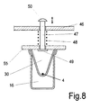
- FIG. 8 is another embodiment of a locking device shown.
- the cooling tube 30 through the bleached lid 55 and the cooling rail 16 is formed.
- On the plate-shaped cover 55 is over the fastener 49 fastens a pin 47.
- the pin 47 is in one Holder 46 movably mounted.
- the holder 46 is fixed like the cooling device arranged in the machine.
- Between cover 55 and holder 46 a spring 48 enclosing the pin is arranged.
- the spring 48 is biased against the holder 46 so that the cover 55 on the cooling rail 16 is held non-positively.
- the pin 47 points to its free End a handle 50 on. By manual actuation of the pin 47 in vertical direction against the spring 48, the cover 55 can thus lift the cooling rail 16. So that the cooling tube 30 is opened so that the thread 4 can be inserted into the cooling rail 16.
- the cooling device according to the invention can also be made in one piece Form the hollow body. In this case the thread goes into the cooling tube threaded. Opening and closing the cooling tube in the longitudinal direction can not.
- FIG. 9 shows an embodiment of a texturing machine with a Protective body shown in the false twist zone. Since the one shown in FIG Texturing machine has essentially the same structure as that 1 becomes the description at this point Fig. 1 referred. The components with the same function have here received identical reference numerals.
- the protective body 116 has a thread 4 without Contact surrounding jacket 132.
- the protective body is at the ends 116 open so that the thread 4 without contact through the protective body 116 runs.
- the protective body 116 extends from the heater outlet to of the cooling device 19, wherein a first section of the cooling device is also enclosed by the jacket 132 of the protective body 116.
- the protective body 116 is connected to an opening in the jacket 132 Suction line 115 connected at its other end to a suction device 14 is coupled.
- the thread 4 is by means of the first
- the delivery mechanism 13 is withdrawn from the supply spool 7 and into a false twist zone guided.
- the false twist zone is the heater 18, the protective body 116, the cooling device 19 and the false twist unit arranged so that a stretching and fixing of the thread within the false twist zone 4 is done.
- the thread 4 is from the false twist zone by the second delivery mechanism 21 deducted and then with the help of a third supplier 23 Shrinkage condition promoted by a second heater 22. This could another between the heater input 22 and the second delivery unit 21 Supplying plant switched. Thanks to the additional delivery facility independent of the stretching in the false twist zone, the thread tensions for shrinking treatment between the third supply plant and the additional one Set the delivery plant separately. After the third supplier 23 the thread 4 is guided to the winding device 9 and to a bobbin 25 wound up.
- the protective body 116 is arranged at the outlet of the heater 18 .
- the interior of the protective body 116 is connected to a suction device 14. So they are on the thread 4 escaping vapors discharged before entering the cooling device 19.
- the protective body 116 which is advantageous, for example, by a Pipe can be connected to a condensate collector. This is done by the on the inner walls of the protective body escaping condensate discharged collectively.
- the cooling device 19 is designed as a cooling rail, in the groove bottom the thread 4 is guided along with contact. Here occur when Entry of the thread into the cooling device vapors from the thread. Around to remove these vapors, the protective body extends over at least a portion of the cooling rail. This could be the protective body be extended so that the entire cooling device itself is located within the protective body 116. In the event that a cooling device with a cooling tube 30 penetrated by the thread is, the protective body 116 is only until immediately before the entry of the Cooling device 19 arranged.
- the thread By removing the vapor of the condensate before the thread enters the cooling device, the thread is cooled more intensively in the cooling device 19. A formation of condensate within the cooling device 19 is avoided. This considerably reduces the contamination of the cooling device. Furthermore, the thread is guided in a substantially dry thread running track within the cooling device 19.
- the jacket of the protective body 116 could be cooled, for example through a flow of cold air.
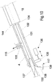
- Fig. 10 is another embodiment of a protective body as it could be used on a texturing machine in FIG. 9.
- the cooling device is through a cooling pipe 137 formed.
- the thread is helical on the outside of the Surface of the cooling tube 137 out.
- Inside is the cooling pipe cooled, for example, by a flowing cooling medium.
- the protective body 116 in turn consists of a jacket 132, one interior 131 penetrated by the thread 4.
- the ends of the protective body 116 are open.
- the jacket 132 has one Opening 133. Concentric to the opening 133 is the suction line 115 on the Coat 132 attached.
- the suction line 115 leads to a suction device (not shown here), so that the interior 131 via the opening 133 and the suction line 115 is connected to the suction device.
- a cooling tube 137 projects into the open end facing the cooling device the interior 131 of the protective body 116.
- the Kahlrohr 137 is looped around the circumference.
- Between the cooling pipe and the Sheath 132 has an opening 130 formed for draining the condensate serves.
- a drain plate 138 is arranged beneath the protective body 116 at the end of the jacket 132 .
- the drain plate 138 leads to one Container 139.
- the container 139 serves to receive the dripping Condensate.
- the protective body 116 is attached to a holder 135. Of the Holder 135 is with an adjusting device arranged in the machine frame 136 coupled. The adjusting device 136 enables movement of the Holder 135 in the axial direction of the protective body 116.
- the adjusting device 136 can be between the heater output 144 and the open end of the protective body 116 formed slot 134 in size change.
- the slot 134 By adjusting the slot 134, the can in the interior 131 incoming ambient air can be set.
- FIG. 11 shows a further exemplary embodiment of a protective body kinked thread running between the heating device and cooling device shown.
- the thread 4 is between the heater 18 and the cooling device 19th guided over a thread guide 146.
- a protective body consisting of two parts arranged.
- the first section 116.1 of the protective body encloses the Thread 4 in the section between the heater 18 and the thread guide 146.
- the second section 116.2 of the protective body encloses the thread 4 in the area between the thread guide 46 and the cooling device 19.
- the area of the interface of the two sections 116.1 and 116.2 is one Suction line 115 connected to the partial ridges, so that the interior of the Protective body in connection with a suction device.
- the protective body consists of a lower part and an upper part exists that are mutually movable. Such an arrangement is shown in FIG shown.
- the inner contour 142 of the lower part 140 is congruent the outer contour 143 of the upper part 141 is formed.
- the upper part 141 is in Circumferentially coupled to the lower part 140.
- the protective body 116 thus formed is in the open state shown.
- the upper part 141 is in the inner region of the lower part 140 swung in. Now a thread 4 can be inserted into the open groove formed will. Then the upper part 141 for closing the protective body twisted out of the inner region of the lower part 140.
- the Protective body shown in the closed state Here the upper part forms 141 and the lower part 140 a closed interior 131. In the Interior 131 runs the thread 4.
- the protective body 116 in one piece with a Longitudinal slot formed in the thread running direction for thread application is.
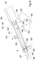
- FIG. 13 shows an exemplary embodiment of a protective body with a nozzle device shown.
- a texturing machine according to FIG. 1 or according to FIG. 9 are used.
- the thread becomes immediate wetted with a cooling fluid after the heat treatment.
- the result additional evaporation of the cooling fluid on the thread leads on the one hand for volatilizing the preparation components in the thread as well as for cooling of thread.
- Fig. 13 points the protective body has a tubular interior 131, which by a Sheath 132 is formed.
- the jacket 132 lies directly with one end face at the heater output 144 of the heater 18. This allows the Thread 4 directly into the interior 131 and on the opposite one Run up side on a cooling tube 137 for cooling.
- the coat 132 has an opening 133 in the central region. Concentric to Opening 133, suction line 115 is attached to jacket 132.
- the Suction line 115 leads to a suction device, such as that in, for example Fig. 1 is shown so that the interior 131 through the opening 133 and Suction line 115 is connected to the suction device 14.
- the cooling tube 137 is on Thread wrapped around the circumference.
- a bulkhead 147 is arranged between the cooling pipe and the jacket 132 .
- the bulkhead encloses it the cooling pipe 137.
- In the bulkhead 147 is on one Place a thread opening 148 on the circumference of the cooling tube so that the thread can emerge freely from the interior 131.
- the thread opening 148 is essentially closed on the opposite side a condensate outlet opening 130 arranged in the jacket.
- the Condensate outlet opening 130 connects the interior 131 to a manifold 157.
- the manifold 157 is with a not shown here Collecting container for condensate connected.
- the condensate outlet is hereby arranged in the area of the jacket 132, which is inside the machine is the deepest.
- the jacket 132 lies in the essentially sealing at the heater outlet 144.
- the jacket 132 opening 156 allows ambient air to enter interior space 131.
- nozzles 149 are spaced apart.
- the Nozzles protrude into the interior 131 such that the thread 4 over a tread 151 formed on the nozzle is guided.
- tread 151 opens a nozzle channel 152 in a funnel shape.
- the nozzle channel 152 is arranged via a line with an outside of the protective body Dosing device, which is designed as a metering pump 150, connected.
- the Dosing pump 150 draws cooling fluid from a container 155.
- the cooling fluid, water, for example, is supplied by the metering pump 150 via the nozzle 149 promoted on the thread or in the interior 131.
- the metering pump 150 can be controlled via a pump control 153.
- the pump controller 153 is connected to a control unit 154.
- the amount of the cooling fluid can be controlled individually specified by the respective pump control.
- the central Control unit 154 can process dependent dosages of the Cooling fluids are made.
- Essential when dosing the cooling fluid is that the in the collecting space or on the thread 4th applied amount is completely evaporated. This prevents an excess of cooling fluid forms in the interior 131.
- the steam will completely discharged via the suction line 115.
- the application of the cooling fluid can - as shown in Fig. 13 - done by several or even by just one nozzle.
- the nozzles can also be advantageously configured as atomizer nozzles. The has the advantage that there is no direct thread contact between the nozzle and the thread is required.
- the atomized cooling fluid is distributed fog-like in the interior 131.
- the supply of the cooling fluid is interrupted by means of the control device 154.
- the control device 154 can advantageously be used for actuation of the folding mechanism of the protective body.
- the nozzles could move out of the thread path when the thread was being applied will.
- the nozzles can be arranged in this way be that the thread is S-shaped or in serpentine lines and the For example, nozzles can be moved sideways and against stops deliberately plunge again.
Landscapes
- Engineering & Computer Science (AREA)
- Textile Engineering (AREA)
- Mechanical Engineering (AREA)
- Yarns And Mechanical Finishing Of Yarns Or Ropes (AREA)
- Treatment Of Fiber Materials (AREA)
- Spinning Methods And Devices For Manufacturing Artificial Fibers (AREA)
- Woven Fabrics (AREA)
Applications Claiming Priority (4)
| Application Number | Priority Date | Filing Date | Title |
|---|---|---|---|
| DE19721805 | 1997-05-24 | ||
| DE19721805 | 1997-05-24 | ||
| DE19728222 | 1997-07-02 | ||
| DE19728222 | 1997-07-02 |
Publications (2)
| Publication Number | Publication Date |
|---|---|
| EP0879907A1 true EP0879907A1 (fr) | 1998-11-25 |
| EP0879907B1 EP0879907B1 (fr) | 2003-04-09 |
Family
ID=26036810
Family Applications (1)
| Application Number | Title | Priority Date | Filing Date |
|---|---|---|---|
| EP98108708A Expired - Lifetime EP0879907B1 (fr) | 1997-05-24 | 1998-05-13 | Machine de texturation |
Country Status (6)
| Country | Link |
|---|---|
| US (1) | US6026636A (fr) |
| EP (1) | EP0879907B1 (fr) |
| CN (1) | CN1100900C (fr) |
| DE (1) | DE59807796D1 (fr) |
| TR (1) | TR199800896A3 (fr) |
| TW (1) | TW376412B (fr) |
Cited By (6)
| Publication number | Priority date | Publication date | Assignee | Title |
|---|---|---|---|---|
| WO2001038620A1 (fr) * | 1999-11-25 | 2001-05-31 | Maschinenfabrik Rieter Ag | Procédé de refroidissement d'un fil filamentaire torsadé |
| US7080501B2 (en) | 2002-04-26 | 2006-07-25 | Saurer Gmbh & Co. Kg | Yarn false twist texturing apparatus |
| DE102011108112A1 (de) * | 2011-07-20 | 2013-01-24 | Oerlikon Textile Gmbh & Co. Kg | Garnbehandlungskammer |
| CN104878496A (zh) * | 2015-05-22 | 2015-09-02 | 桐乡市新丝利纺织有限公司 | 低温双色处理装置 |
| WO2018059743A1 (fr) * | 2016-09-28 | 2018-04-05 | Oerlikon Textile Gmbh & Co. Kg | Procédé et dispositif de refroidissement d'un fil synthétique |
| WO2018065123A1 (fr) * | 2016-10-08 | 2018-04-12 | Oerlikon Textile Gmbh & Co. Kg | Dispositif de refroidissement d'un fil chauffé |
Families Citing this family (9)
| Publication number | Priority date | Publication date | Assignee | Title |
|---|---|---|---|---|
| WO2000049212A1 (fr) * | 1999-02-16 | 2000-08-24 | Temco Textilmaschinenkomponenten Gmbh | Procede d'insertion et d'etalement de fil, et dispositif de texturation par fausse torsion |
| JP3569869B2 (ja) * | 2001-10-05 | 2004-09-29 | 東洋電機株式会社 | 合成繊維糸条の熱処理装置 |
| DE10162299A1 (de) * | 2001-12-19 | 2003-07-03 | Barmag Barmer Maschf | Texturiermaschine |
| CN112011922B (zh) * | 2019-05-30 | 2024-04-12 | 欧瑞康纺织有限及两合公司 | 一种纺织机械的利用冷却液将合成纤维冷却的冷却设备 |
| JP7637584B2 (ja) * | 2021-07-13 | 2025-02-28 | Tmtマシナリー株式会社 | 冷却装置、及び糸加工機 |
| CN115307064A (zh) * | 2022-08-15 | 2022-11-08 | 广东新会美达锦纶股份有限公司 | 一种加弹机热箱温度变异的检修装置及其检修方法 |
| CN116446092B (zh) * | 2023-06-15 | 2023-08-18 | 山东森荣新材料股份有限公司 | 纤维长丝定型装置 |
| CN119082964A (zh) * | 2024-08-28 | 2024-12-06 | 江苏普来得科技发展有限公司 | 一种自动纤维机 |
| CN119221170A (zh) * | 2024-09-24 | 2024-12-31 | 江苏普来得科技发展有限公司 | 化学纤维冷却系统、方法、拉伸变形装置及化学纤维设备 |
Citations (8)
| Publication number | Priority date | Publication date | Assignee | Title |
|---|---|---|---|---|
| US3368335A (en) * | 1966-02-03 | 1968-02-13 | Heberlein & Co Ag | Apparatus for the treatment of yarns |
| DE4138509A1 (de) * | 1991-01-21 | 1992-08-20 | Barmag Barmer Maschf | Kuehlvorrichtung fuer einen laufenden faden |
| DE4227115A1 (de) * | 1991-08-26 | 1993-03-04 | Barmag Barmer Maschf | Falschzwirnkraeuselmaschine |
| JPH05239725A (ja) * | 1992-02-24 | 1993-09-17 | Teijin Ltd | 高速仮撚機用冷却装置 |
| EP0571975A1 (fr) * | 1992-05-27 | 1993-12-01 | TEIJIN SEIKI CO. Ltd. | Machine de texturation |
| US5359845A (en) * | 1992-04-29 | 1994-11-01 | Icbt Roanne | Process and apparatus for cooling a heated yarn |
| US5406782A (en) * | 1992-03-23 | 1995-04-18 | Murata Kikai Kabushiki Kaisha | Drawing false-twisting method and a drawing false-twister |
| EP0744481A1 (fr) * | 1995-05-23 | 1996-11-27 | Rieter Scragg Limited | Machine textile |
Family Cites Families (6)
| Publication number | Priority date | Publication date | Assignee | Title |
|---|---|---|---|---|
| US2958921A (en) * | 1954-11-26 | 1960-11-08 | Klinger Mfg Company | Heat treatment of thermoplastic or thermosetting yarn |
| US3237392A (en) * | 1963-08-14 | 1966-03-01 | Chavanoz Moulinage Retorderie | Process for producing bulked yarn |
| US4380890A (en) * | 1981-08-06 | 1983-04-26 | Milliken Research Corporation | Belt false twisting apparatus |
| DE59007713D1 (de) * | 1989-08-09 | 1994-12-22 | Barmag Barmer Maschf | Heizeinrichtung. |
| CN1045320C (zh) * | 1992-10-08 | 1999-09-29 | 巴马格股份公司 | 假捻卷曲机 |
| TW317579B (fr) * | 1995-04-11 | 1997-10-11 | Barmag Barmer Maschf |
-
1998
- 1998-05-13 EP EP98108708A patent/EP0879907B1/fr not_active Expired - Lifetime
- 1998-05-13 DE DE59807796T patent/DE59807796D1/de not_active Expired - Fee Related
- 1998-05-20 TR TR1998/00896A patent/TR199800896A3/tr unknown
- 1998-05-22 US US09/083,721 patent/US6026636A/en not_active Expired - Fee Related
- 1998-05-22 TW TW087107954A patent/TW376412B/zh not_active IP Right Cessation
- 1998-05-22 CN CN98108957A patent/CN1100900C/zh not_active Expired - Fee Related
Patent Citations (8)
| Publication number | Priority date | Publication date | Assignee | Title |
|---|---|---|---|---|
| US3368335A (en) * | 1966-02-03 | 1968-02-13 | Heberlein & Co Ag | Apparatus for the treatment of yarns |
| DE4138509A1 (de) * | 1991-01-21 | 1992-08-20 | Barmag Barmer Maschf | Kuehlvorrichtung fuer einen laufenden faden |
| DE4227115A1 (de) * | 1991-08-26 | 1993-03-04 | Barmag Barmer Maschf | Falschzwirnkraeuselmaschine |
| JPH05239725A (ja) * | 1992-02-24 | 1993-09-17 | Teijin Ltd | 高速仮撚機用冷却装置 |
| US5406782A (en) * | 1992-03-23 | 1995-04-18 | Murata Kikai Kabushiki Kaisha | Drawing false-twisting method and a drawing false-twister |
| US5359845A (en) * | 1992-04-29 | 1994-11-01 | Icbt Roanne | Process and apparatus for cooling a heated yarn |
| EP0571975A1 (fr) * | 1992-05-27 | 1993-12-01 | TEIJIN SEIKI CO. Ltd. | Machine de texturation |
| EP0744481A1 (fr) * | 1995-05-23 | 1996-11-27 | Rieter Scragg Limited | Machine textile |
Non-Patent Citations (1)
| Title |
|---|
| DATABASE WPI Section Ch Week 9342, Derwent World Patents Index; Class F02, AN 93-331861, XP002075506 * |
Cited By (6)
| Publication number | Priority date | Publication date | Assignee | Title |
|---|---|---|---|---|
| WO2001038620A1 (fr) * | 1999-11-25 | 2001-05-31 | Maschinenfabrik Rieter Ag | Procédé de refroidissement d'un fil filamentaire torsadé |
| US7080501B2 (en) | 2002-04-26 | 2006-07-25 | Saurer Gmbh & Co. Kg | Yarn false twist texturing apparatus |
| DE102011108112A1 (de) * | 2011-07-20 | 2013-01-24 | Oerlikon Textile Gmbh & Co. Kg | Garnbehandlungskammer |
| CN104878496A (zh) * | 2015-05-22 | 2015-09-02 | 桐乡市新丝利纺织有限公司 | 低温双色处理装置 |
| WO2018059743A1 (fr) * | 2016-09-28 | 2018-04-05 | Oerlikon Textile Gmbh & Co. Kg | Procédé et dispositif de refroidissement d'un fil synthétique |
| WO2018065123A1 (fr) * | 2016-10-08 | 2018-04-12 | Oerlikon Textile Gmbh & Co. Kg | Dispositif de refroidissement d'un fil chauffé |
Also Published As
| Publication number | Publication date |
|---|---|
| EP0879907B1 (fr) | 2003-04-09 |
| US6026636A (en) | 2000-02-22 |
| TW376412B (en) | 1999-12-11 |
| TR199800896A2 (xx) | 1998-12-21 |
| CN1100900C (zh) | 2003-02-05 |
| DE59807796D1 (de) | 2003-05-15 |
| CN1200413A (zh) | 1998-12-02 |
| TR199800896A3 (tr) | 1998-12-21 |
Similar Documents
| Publication | Publication Date | Title |
|---|---|---|
| EP0879907B1 (fr) | Machine de texturation | |
| EP2147137B1 (fr) | Dispositif de filage par fusion et de bobinage de fils synthétiques | |
| EP0937791B1 (fr) | Procédé et dispositif pout le filage d'un fil multifilament | |
| DE102009021131A1 (de) | Vorrichtung zum Schmelzspinnen und Aufwickeln einer Mehrzahl von Fäden sowie ein Verfahren zum Führen mehrerer Fäden beim Schmelzspinnen und Aufwickeln | |
| DE2200686B2 (de) | Faserbandauflösevorrichtung | |
| DE4309179A1 (de) | Streck-Falschdrehverfahren und Streck-Falschdrehvorrichtung | |
| EP3276057A1 (fr) | Unité guide-fil, métier à tisser à extrémité ouverte et procédé de fonctionnement d'un poste de filage | |
| CH679679A5 (fr) | ||
| EP1501968B1 (fr) | Machine de texturation | |
| DE3639031C2 (fr) | ||
| EP0176937B1 (fr) | Procédé de fabrication de fil non texturé | |
| DE10053073A1 (de) | Spinnvorrichtung | |
| DE19506369A1 (de) | Verfahren und Vorrichtung zum Heizen eines synthetischen Fadens | |
| DE69303668T2 (de) | Texturiermaschine | |
| CH646116A5 (de) | Entstaubungsvorrichtung an spulstellen einer spulmaschine. | |
| EP1114212B1 (fr) | Machine de texturation | |
| DE3534079C2 (de) | Verfahren zum Herstellen von Glattgarn | |
| DE10234554A1 (de) | Texturiermaschine | |
| DE2752232A1 (de) | Falschdrall-strecktexturiermaschine | |
| DE19531987C2 (de) | Fadeneinfädeleinrichtung an einer Strecktexturiermaschine | |
| EP1328671B1 (fr) | Machine de fausse torsion | |
| DE3306459A1 (de) | Heizeinrichtung fuer eine kraeuselmaschine | |
| DE2039443C3 (de) | Vorrichtung zum Überführen eines textilen Fadens von einer ersten Behandlungszone zu einer zweiten Behandlungszone | |
| EP3148910B1 (fr) | Dispositif de va-et-vient pour un metier a filer et metier a filer avec un tel dispositif | |
| EP1377515B1 (fr) | Procede et dispositif pour humidifier un fil |
Legal Events
| Date | Code | Title | Description |
|---|---|---|---|
| PUAI | Public reference made under article 153(3) epc to a published international application that has entered the european phase |
Free format text: ORIGINAL CODE: 0009012 |
|
| AK | Designated contracting states |
Kind code of ref document: A1 Designated state(s): CH DE FR GB IT LI |
|
| AX | Request for extension of the european patent |
Free format text: AL;LT;LV;MK;RO;SI |
|
| 17P | Request for examination filed |
Effective date: 19990413 |
|
| AKX | Designation fees paid |
Free format text: CH DE FR GB IT LI |
|
| 17Q | First examination report despatched |
Effective date: 20011123 |
|
| GRAH | Despatch of communication of intention to grant a patent |
Free format text: ORIGINAL CODE: EPIDOS IGRA |
|
| GRAH | Despatch of communication of intention to grant a patent |
Free format text: ORIGINAL CODE: EPIDOS IGRA |
|
| GRAH | Despatch of communication of intention to grant a patent |
Free format text: ORIGINAL CODE: EPIDOS IGRA |
|
| GRAA | (expected) grant |
Free format text: ORIGINAL CODE: 0009210 |
|
| AK | Designated contracting states |
Designated state(s): CH DE FR GB IT LI |
|
| REG | Reference to a national code |
Ref country code: GB Ref legal event code: FG4D Free format text: NOT ENGLISH |
|
| REG | Reference to a national code |
Ref country code: CH Ref legal event code: EP |
|
| REG | Reference to a national code |
Ref country code: CH Ref legal event code: NV Representative=s name: BARMAG GMBH ENGINEERING AND MANUFACTURING |
|
| GBT | Gb: translation of ep patent filed (gb section 77(6)(a)/1977) |
Effective date: 20030806 |
|
| ET | Fr: translation filed | ||
| PLBE | No opposition filed within time limit |
Free format text: ORIGINAL CODE: 0009261 |
|
| STAA | Information on the status of an ep patent application or granted ep patent |
Free format text: STATUS: NO OPPOSITION FILED WITHIN TIME LIMIT |
|
| 26N | No opposition filed |
Effective date: 20040112 |
|
| PGFP | Annual fee paid to national office [announced via postgrant information from national office to epo] |
Ref country code: CH Payment date: 20070522 Year of fee payment: 10 |
|
| PGFP | Annual fee paid to national office [announced via postgrant information from national office to epo] |
Ref country code: DE Payment date: 20070629 Year of fee payment: 10 |
|
| PGFP | Annual fee paid to national office [announced via postgrant information from national office to epo] |
Ref country code: GB Payment date: 20070419 Year of fee payment: 10 |
|
| PGFP | Annual fee paid to national office [announced via postgrant information from national office to epo] |
Ref country code: IT Payment date: 20070531 Year of fee payment: 10 |
|
| PGFP | Annual fee paid to national office [announced via postgrant information from national office to epo] |
Ref country code: FR Payment date: 20070518 Year of fee payment: 10 |
|
| REG | Reference to a national code |
Ref country code: CH Ref legal event code: PL |
|
| GBPC | Gb: european patent ceased through non-payment of renewal fee |
Effective date: 20080513 |
|
| PG25 | Lapsed in a contracting state [announced via postgrant information from national office to epo] |
Ref country code: LI Free format text: LAPSE BECAUSE OF NON-PAYMENT OF DUE FEES Effective date: 20080531 Ref country code: CH Free format text: LAPSE BECAUSE OF NON-PAYMENT OF DUE FEES Effective date: 20080531 |
|
| REG | Reference to a national code |
Ref country code: FR Ref legal event code: ST Effective date: 20090119 |
|
| PG25 | Lapsed in a contracting state [announced via postgrant information from national office to epo] |
Ref country code: FR Free format text: LAPSE BECAUSE OF NON-PAYMENT OF DUE FEES Effective date: 20080602 Ref country code: DE Free format text: LAPSE BECAUSE OF NON-PAYMENT OF DUE FEES Effective date: 20081202 |
|
| PG25 | Lapsed in a contracting state [announced via postgrant information from national office to epo] |
Ref country code: GB Free format text: LAPSE BECAUSE OF NON-PAYMENT OF DUE FEES Effective date: 20080513 |
|
| PG25 | Lapsed in a contracting state [announced via postgrant information from national office to epo] |
Ref country code: IT Free format text: LAPSE BECAUSE OF NON-PAYMENT OF DUE FEES Effective date: 20080513 |