EP0880019A2 - Ein Verfahren zum Voraussagen der Reifenleistung auf Strassen mit Regenrinnen - Google Patents
Ein Verfahren zum Voraussagen der Reifenleistung auf Strassen mit Regenrinnen Download PDFInfo
- Publication number
- EP0880019A2 EP0880019A2 EP98250143A EP98250143A EP0880019A2 EP 0880019 A2 EP0880019 A2 EP 0880019A2 EP 98250143 A EP98250143 A EP 98250143A EP 98250143 A EP98250143 A EP 98250143A EP 0880019 A2 EP0880019 A2 EP 0880019A2
- Authority
- EP
- European Patent Office
- Prior art keywords
- tire
- data
- subjective
- rain groove
- objective
- Prior art date
- Legal status (The legal status is an assumption and is not a legal conclusion. Google has not performed a legal analysis and makes no representation as to the accuracy of the status listed.)
- Granted
Links
Images


Classifications
-
- G—PHYSICS
- G01—MEASURING; TESTING
- G01M—TESTING STATIC OR DYNAMIC BALANCE OF MACHINES OR STRUCTURES; TESTING OF STRUCTURES OR APPARATUS, NOT OTHERWISE PROVIDED FOR
- G01M17/00—Testing of vehicles
- G01M17/007—Wheeled or endless-tracked vehicles
- G01M17/02—Tyres
- G01M17/022—Tyres the tyre co-operating with rotatable rolls
Definitions
- the present invention generally relates to test methods for evaluating tire performance. More particularly, the present invention is related to a method of testing a tire for rain groove wander and a method for correlating a subjective field analysis of rain groove wander for tires to an objective analysis technique that does not require vehicle testing to predict tire performance on rain groove roadways.
- tire performance was evaluated subjectively by placing a set of tires on a test vehicle and performing field evaluations.
- the driver would operate the vehicle on the grooved roadway and provide a subjective rating regarding the vehicle's handling and rideability as the vehicle traveled along the grooved highway as well as translated across various lanes to simulate actual driving conditions.
- Such subjective evaluations are very valuable in that they provide actual data reflecting the tire performance that correlates closely with customer satisfaction.
- Such subjective field analysis is both a time-consuming and an expensive process.
- four vehicle tires must be provided for the subjective analysis in order to provide an accurate reflection of the driving performance of the tires on the vehicle. Therefore, when testing a prototype tire design, four such tires must be manufactured.
- a method of testing a tire for rain groove wander which allows a tire to be objectively tested in a laboratory wherein the objective test results closely correlate with subjective field analysis type data, thereby allowing for the subjective tire performance to be predicted while precluding the need for subjective field analysis of the particular tire.
- the method also allows objective testing of a single tire size by varying the radial loading in the laboratory test set, thereby precluding the construction of multiple tire sizes each having the same tread design.
- the method simulates rain groove road conditions and correlates objective analysis data obtained via the laboratory test methodology with subjective field analysis data of rain groove wander tire performance of other tires, thereby providing a substantially accurate technique for identifying the subjective performance of the tire without having to conduct the field testing to obtain such subjective field analysis data.
- the method substantially reduces the cost required to design and test a prototype tire design and the time required to implement tire design testing.
- a method of predicting tire performance on rain groove roadways by testing a tire includes simulating a rain groove road condition and measuring one or more forces acting on a tire which is operating on the simulated road condition. The one or more measured forces are then correlated to subjective tire performance data and the subjective tire performance is predicted based on the correlation, thereby effectively testing the rain groove wander performance of the tire without having to perform field testing.
- the step of simulating the rain groove road conditions may include placing the tire in rotatable contact with a grooved surface and moving the grooved surface such that the tire rotates and remains in contact with the grooved surface, thereby simulating the tire traveling on a rain groove roadway.
- the method of testing a tire for rain groove wander may further include applying a variable radial loading on the tire to simulate the tire performance when used by various vehicle types.
- the method may also include translating the tire axially across the moving grooved surface to thereby simulate a lateral vehicle movement on a rain groove roadway.
- the step of measuring the one or more forces acting on the tire under the simulated rain groove road conditions includes measuring a lateral force acting on the tire which is stored as data.
- the data is processed to place the processed data in a format that correlates substantially closely with the subjective field analysis tire performance data.
- One option of data processing may include time filtering the data, wherein the data within each of a plurality of prescribed time periods are averaged and compressing the data such that each piece of data associated with a particular lateral position of the tire with respect to a groove of the grooved surface is graphically overlaid.
- the compressed data is then normalized with respect to a mean lateral force measured across the grooved surface and a peak-to-peak force difference of the normalized data is calculated for use in correlating the measured forces to the subjective field analysis tire performance data.
- a predetermined number of Fourier coefficients may be extracted from the normalized compressed data and the Fourier coefficients are subsequently squared and summed together for use in correlating the measured forces to the subjective tire performance data.
- a method for correlating a subjective field analysis of rain groove wander for tires to an objective laboratory analysis technique that does not require vehicle testing includes collecting subjective field measurements of rain groove wander for a particular tire. During such field testing, objective field measurements of one or more forces acting on the tire are concurrently collected with the collection of the subjective field measurements and the subjective and objective field measurements are correlated. Objective lab measurements of one or more forces acting on the tire under simulated rain groove roadway conditions are collected and a correlation between the objective field measurement data and the objective lab measurement data is identified, thereby effectively correlating the objective lab measurement data to the subjective field measurement data.
- the step of collecting subjective field measurements includes driving a vehicle having a set of tires for evaluation on a rain groove roadway and providing a subjective rating during the driving, wherein the subjective rating reflects a composite handling and rideability characteristic of the vehicle sensed by a driver of the vehicle.
- the step of collecting objective field measurements includes driving the vehicle having a set of tires for evaluation on the rain groove roadway and measuring one or more forces exerted by the grooves on the rain groove roadway on the tires.
- the step of collecting objective lab measurements of forces acting on the tire under simulated rain groove roadway conditions includes simulating the rain groove road conditions, measuring one or more forces acting on the tire which is operating in the simulated rain groove road conditions, and processing the data for subsequent correlation of the processed data to the subjective tire performance analysis data.
- a method of selecting a desired tire based on a desired subjective rain groove roadway characteristic without performing a subjective field tire evaluation includes selecting a desired subjective rain groove roadway tire performance characteristic. An objective force value that correlates with the desired subjective rain groove roadway tire performance characteristic is identified and a simulated force characteristic based on the identified objective force is identified. One or more tires are then simulated and the tire that meets the required simulated force characteristic is selected, thereby selecting the tire having the desired subjective rain groove roadway tire performance characteristic.
- a method for testing a tire for rain groove wander includes a subjective field testing of a vehicle utilizing various sets of tires for subjective analysis testing on a rain groove roadway.
- a driver while driving the vehicle on the rain groove roadway, provides a subjective analysis of the handling and rideability of the vehicle caused by the interaction between the tires and the rain groove roadway.
- an objective field analysis is also taking place wherein a force measurement apparatus (for example, a load cell) is attached to one or more of the vehicle spindles during field testing of the tires.
- the force measurement apparatus measures one or more forces acting on the tires and may be operable to record the three orthogonal forces as well as the three moment forces that fully define the range of motion of the tire with respect to the rain groove roadway.
- the force measurement apparatus measures at least the lateral force exerted by the rain groove roadway upon the tires.
- the data is then collected and processed to correlate with the collected subjective field analysis data. Therefore, the field analysis results in a collection of the subjective field data as well as a concurrent set of objective field analysis data for various sets of tires at a single radial loading. Once obtained, additional field analysis is not needed and tire performance on rain groove roadways may be predicted based on objective lab testing.
- Objective lab testing is conducted using a laboratory test set apparatus (which will be subsequently described in greater detail) which preferably records the lateral forces exerted on the tires that were tested in the field testing by the test set which simulates rain groove roadway conditions.
- objective laboratory analysis data is collected for each tire in which correlation between the various pieces of lab and the collected field data may be explored.
- the present invention contemplates processing one or more pieces of data in order to establish a substantially close correlation between the objective laboratory data and the subjective field analysis data to thereby predict a tire's subjective performance via tire testing within the laboratory and thereby preclude further subjective field analysis which is both costly and time consuming.
- Figure 1A is a system level schematic diagram which illustrates a laboratory test set 10, in which a tire 12 is tested under simulated rain groove roadway conditions.
- the laboratory test set 10 includes a cylindrical drum 14 having a substantially larger diameter than the diameter of the tire 12 to preferably simulate a substantially flat road condition as would be experienced in normal vehicle field testing.
- the cylindrical drum 14 is approximately ten feet in diameter and is surrounded by an aluminum collar 16 which is approximately three-eighths inch thick.
- the aluminum collar 16 has grooves formed on its surface to simulate the rain groove roadway which are machined having 0.1 inch grooves on three-quarter inch centers.
- the grooves formed within the collar 16 may have different widths and different centering spacings to simulate other type roadway conditions.
- the collar 16 may be machined or scratched having uneven or nonperiodic movements in order to facilitate simulation of the uneven or nonperiodic character of the grooves within actual rain grooved roadways.
- a tire test set 18 places the tire 12 in rotatable contact with the cylindrical drum 14 and aluminum collar 16 via a rim 18 (containing a load cell) attached to an axle 20 which is controlled by a test control and data collection module 22.
- the test control and data collection module 22 is operable to provide various test characteristics such as the radial loading placed upon the tire 12 to simulate various vehicle weights that the tire may experience.
- the module 22 is also operable to vary the slip of the tire 12 with respect to the drum 14 and collar 16 to further simulate the impact of misaligned tires with respect to the simulated grooved roadway. In this particular embodiment, a zero degree slip is utilized, however, the slip may be modified to gather further data.
- the module 22 is also operable to translate the tire laterally (axially) across the simulated rain groove roadway (drum 14 and collar 16) in order to simulate a vehicle changing lanes in order for the various forces within the grooved roadway to act upon the tires.
- the module 22 also collects data with respect to the forces acting upon the tire due to the simulated roadway conditions via the load cell located on the rim 18.
- the translation speed is such that a tire tread passes over a groove on the collar 16 every fourteen seconds and the data (representing at least the lateral force exerted on the tire 12) is collected at a sampling rate of 50 Hz.
- the speed experienced by the tire 12 may be modified or varied by altering the rotational speed of the cylindrical drum 14 to simulate varying speeds or vehicle acceleration or deceleration.
- Figure 1B illustrates the translational functionality of the tire 12 across the collar 16 and the drum 14 via the axle 20.
- Figure 2 is a block diagram 24 which illustrates the various steps (26-36) taken to create a correlation-type methodology between the collected subjective field measurements representing a variety of tires and the collected laboratory measurements of a particular tire under test.
- Figure 3A is a block diagram illustrating the various steps in the objective lab data collection method of step 32
- Figure 3B is a block diagram which illustrates the various steps (46-50) in the data processing step 44 within the objective lab data collection methodology 32 of Figure 3A.
- the correlation step 30 may be discontinued and subsequently all subsequent tire testing may take place via the objective data collection method 32, thereby precluding further testing via field analysis which is both costly and time consuming.
- the cylindrical drum 14 and collar 16 are rotated at step 38 and the tire 12 is translated across the surface of the collar 16 at step 40 via the test control and data collection module 22.
- lateral forces are recorded by the test control and data collection module 22 via the load cell which represent the lateral forces exerted by the simulated rain groove roadway on the tires 12.
- the lateral forces are measured, however, alternatively the test control and data collection module 22 may also record various other forces which are exerted upon the tire 12 for further analysis or correlation.
- the data processing step 44 is directed primarily at placing the data in a format that correlates substantially closely with the subjective field performance data.
- a data processing methodology is illustrated by Figure 3B and further illustrated in the accompanying graphs of Figures 4A-4C, 5, 6A, 6B and 7.
- other data processing methods are also contemplated by the present invention.
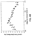
- Figure 3B is a block diagram illustrating various steps taken in the data processing method 44. Although various data processing steps may be undertaken, an exemplary embodiment involves the following. First, the collected lab data is filtered at step 46 and subsequently compressed at step 48 and normalized at step 50. The result of the filtering step 46 is illustrated in Figure 4A which illustrates the recorded lateral force in pounds with respect to the time in which the test was conducted. In this particular embodiment, lateral force measurements were recorded at a sampling rate of 50 Hz while the tire 12 was translated laterally across the drum 14 at a speed at which a tire tread would pass over a groove every fourteen seconds. Furthermore, the data within Figure 4A was collected at one particular radial loading value. The collected data is then filtered by time averaging the data every second.
- Figure 4A illustrates one particular data filtering method 46. Other types of filtering may be performed as desired.
- Data compression may then be performed via the data compressing step 48, the result of which is illustrated in Figure 4B.
- the lateral forces exerted on the tire for each one groove spacing are overlaid since, as illustrated in Figure 4A, the lateral force distribution is substantially periodic in nature. Therefore, either all or a portion of the time filtered data from Figure 4A may be graphically viewed over one groove spacing range and thereby compressed as illustrated in Figure 4B.
- Figure 4B also illustrates a normalization of the data (step 50 of Figure 3B) about the mean lateral force in order for simplification of subsequent data processing.
- the data may be maintained in its unnormalized state.
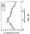
- Figure 4C is a graph illustrating the normalized, compressed lateral force data taken from translation directions both toward and away from the test control and data collection module 22.
- Figure 4C illustrates that the lateral forces exerted on the tire 12 by the simulated rain groove roadway are substantially identical in either translation direction. Therefore, test data may be taken in either direction or both directions as desired.
- the data is taken in one direction in order to shorten the test time for the lab data collection.
- one may wish to record the data in both translation directions and compare that data in order to confirm that there are no anomalies in the lab test apparatus 10 to thereby provide redundancy and improved accuracy in the laboratory data collection process.
- Further data processing may then take place as desired in order to identify a substantially close correlation between the collected laboratory data and the subjective field performance data.
- Figures 5 and 7 are graphs which illustrate the result of one exemplary data processing methodology which takes the time filtered, compressed and normalized data of Figures 4A and 4B and utilizes that data to calculate a peak-to-peak lateral force value along the groove spacing.
- the peak-to-peak lateral force value is calculated as approximately 8.5 lbs. for a particular tire at a particular radial loading.
- Various peak-to-peak values are calculated as the radial loading for a particular tire is varied. Note that collecting objective lab data at various radial loadings is straightforward since the test set 18 is operable to vary the radial loading on the tire 12.
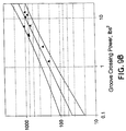
- Figure 7 is a graph which illustrates the averaging of the peak-to-peak lateral force values at each radial load value in which the various tires are averaged together to form a composite peak-to-peak characteristic over radial loading. This composite radial loading may then be utilized as a correlation curve in correlating the objective lab test data to the subjective tire performance data.
- Figure 6A illustrates the results of an alternative data processing methodology in which the time filtered, compressed and normalized lateral force data of Figures 4A and 4B is processed by extracting Fourier coefficients.
- Fourier coefficients may be extracted via conventional signal processing techniques.
- Figure 6A represents the lateral force amplitude for various Fourier coefficients according to their harmonic number.
- One may choose the resolution of the number of harmonic coefficients for extraction. In this exemplary embodiment, the number of coefficients was chosen to be four since four coefficients appear to provide sufficient resolution for subsequent correlation to the subjective field tire performance data.
- fewer Fourier coefficients may be extracted to provide sufficient correlation one may do so, and further, one may also choose additional Fourier coefficients in order to more closely or more accurately provide correlation to the subjective field tire performance data.
- Figure 6B graphically illustrates a subsequent mathematical operation performed on the extracted Fourier coefficients of Figure 6A by squaring the amplitudes of each coefficient and summing those amplitudes together to provide a harmonic power (lb 2 ) which is categorized and subsequently defined in this present invention as the groove crossing power.
- Figure 7 illustrates the groove crossing power with respect to radial loading in order to provide a correlation between groove crossing power (representing the objective lab test data) and the subjective field tire performance data.
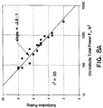
- Figure 8A illustrates the correlation between the subjective field test data (on a 1 to 10 point scale) and the processed objective field test data that was collected concurrently with the subjective data, which is the square of the lateral forces exerted on the tires 12 (on-vehicle total power Fy).
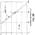
- Figure 8B also illustrates the same type of correlation for a different vehicle (effectively a variation in radial loading) and the differing slopes of the curves in Figures 8A and 8B represent the different vehicle sensitivities.
- smaller cars which result in lower radial loading
- the subjective field test data will be a function of the type of vehicle used to test the tires.
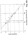
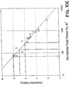
- Figures 9A and 9B are graphs which illustrate the correlation between the processed objective field test data and the processed objective lab test data. Both graphs utilize the Fourier coefficient extraction processing technique of Figures 6A, 6B and 7 to establish the correlation.
- the correlation although not exact, provides an 80% confidence prediction capability (as illustrated by the 80% prediction bands in Figures 9A and 9B) which, in this particular embodiment, is a sufficiently close correlation for the subjective tire performance prediction.
- An 80% prediction confidence correlates to a ⁇ 1 subjective rating point prediction which will be explained in greater detail with respect to Figures 10A-10C. Therefore, by performing objective lab testing of a prototype tire, one may predict the subjective field performance characteristics of the tire within ⁇ 1 subjective rating point without performing subsequent field testing.
- Sources of correlation error are at least the following.
- the tire angle of attack on the simulated test set 10 is different than in the field, which means that the grooves on the simulated test set 10 are straight, while the grooves will vary on an actual roadway.
- Another source of correlation error is due to the translation control of the module 22 not exactly simulating the actual driving conditions in that the translation frequency in the test set 10 was low and the slip angle was fixed.
- the drum 14 is curved and the collar 16 (in this embodiment) is made of aluminum which alters the tire footprint dynamics with respect to the actual rain groove roadway conditions.
- the grooves on the collar 16 are machined on the lab test set 10 which results in square edges with precise spacings while the actual roadway grooves are more rounded and spaced with less precision due to use and wear.
- Figures 10A-10C are graphs which illustrate how objective lab test data is used to predict the subjective field performance of a particular tire.
- Figure 10A illustrates the correlation between the subjective field rating and the processed objective field data. Therefore, as illustrated, if one wishes to have a tire performance rating of about 7.0, one must obtain a total power (Fy) during the objective field testing of about 150 lbs. 2 Then, one may place the prototype tire on the test set 10, measure the forces and process it as data to obtain the groove crossing power (or alternatively use another processing methodology which provides sufficiently close correlation) at a particular radial loading (which matches the radial loading exerted by the vehicle in the field testing). As illustrated in Figure 10B, the groove crossing power needs to be 1.0 lbs. 2 (within 80% certainty).
Landscapes
- Physics & Mathematics (AREA)
- General Physics & Mathematics (AREA)
- Tires In General (AREA)
Applications Claiming Priority (2)
| Application Number | Priority Date | Filing Date | Title |
|---|---|---|---|
| US847449 | 1997-04-24 | ||
| US08/847,449 US6155110A (en) | 1997-04-24 | 1997-04-24 | Method for predicting tire performance on rain groove roadways |
Publications (3)
| Publication Number | Publication Date |
|---|---|
| EP0880019A2 true EP0880019A2 (de) | 1998-11-25 |
| EP0880019A3 EP0880019A3 (de) | 1999-11-17 |
| EP0880019B1 EP0880019B1 (de) | 2005-06-01 |
Family
ID=25300650
Family Applications (1)
| Application Number | Title | Priority Date | Filing Date |
|---|---|---|---|
| EP98250143A Expired - Lifetime EP0880019B1 (de) | 1997-04-24 | 1998-04-24 | Ein Verfahren zum Voraussagen der Reifenleistung auf Strassen mit Regenrinnen |
Country Status (5)
| Country | Link |
|---|---|
| US (1) | US6155110A (de) |
| EP (1) | EP0880019B1 (de) |
| JP (1) | JP4063398B2 (de) |
| CA (1) | CA2235641A1 (de) |
| DE (1) | DE69830362T2 (de) |
Cited By (2)
| Publication number | Priority date | Publication date | Assignee | Title |
|---|---|---|---|---|
| WO2002058947A3 (en) * | 2001-01-26 | 2002-12-12 | Bridgestone Firestone North Am | A method of wear testing a tire |
| US7228732B2 (en) | 2001-01-26 | 2007-06-12 | Bridgestone Firestone North American Tire, Llc | Tire wear analysis method |
Families Citing this family (8)
| Publication number | Priority date | Publication date | Assignee | Title |
|---|---|---|---|---|
| KR101414991B1 (ko) * | 2007-06-26 | 2014-07-04 | 가부시키가이샤 브리지스톤 | 타이어 트레드 마모 시험 장비에 대한 측방향 위치 제어 |
| FR2918749B1 (fr) * | 2007-07-12 | 2009-10-09 | Michelin Soc Tech | Procede d'evaluation de l'adherence transversale d'un pneu sur un sol enneige |
| US7978093B2 (en) * | 2007-11-09 | 2011-07-12 | Bridgestone Americas Tire Operations, Llc | Comparative tire animation |
| FR2959046B1 (fr) * | 2010-04-19 | 2012-06-15 | Michelin Soc Tech | Methode de controle de l'aspect de la surface d'un pneumatique |
| JP7011453B2 (ja) * | 2017-12-07 | 2022-01-26 | Toyo Tire株式会社 | タイヤ騒音試験装置及び方法 |
| JP7011452B2 (ja) * | 2017-12-07 | 2022-01-26 | Toyo Tire株式会社 | タイヤ騒音試験装置及び方法 |
| KR102185736B1 (ko) * | 2019-06-04 | 2020-12-02 | 한국도로공사 | 노면 모사 장치 및 이를 이용한 주행성 평가 시스템. |
| JP7751437B2 (ja) * | 2021-09-29 | 2025-10-08 | Toyo Tire株式会社 | グルーブワンダリング性能の評価方法 |
Family Cites Families (14)
| Publication number | Priority date | Publication date | Assignee | Title |
|---|---|---|---|---|
| US4251931A (en) * | 1979-04-11 | 1981-02-24 | The United States Of America As Represented By The Secretary Of The Navy | Terrain vehicle simulator contour measuring and storage device |
| US4455866A (en) * | 1982-09-22 | 1984-06-26 | Barrigar Robert H | Motor vehicle testing apparatus |
| US4584873A (en) * | 1984-08-27 | 1986-04-29 | Ongaro Dynamics, Ltd. | Integrated tire conditioning system and method |
| US4593557A (en) * | 1985-02-26 | 1986-06-10 | Uniroyal Tire Company, Inc. | Tire testing apparatus |
| US4969212A (en) * | 1989-02-01 | 1990-11-06 | The Goodyear Tire & Rubber Company | Quantitative measurement of handling characteristics of tires and/or vehicle/tire combinations |
| JPH0756464B2 (ja) * | 1990-02-01 | 1995-06-14 | 住友ゴム工業株式会社 | タイヤ接地形状・接地圧測定装置 |
| US5113688A (en) * | 1991-03-19 | 1992-05-19 | The Goodyear Tire & Rubber Company | Laboratory traction test |
| ATE128767T1 (de) * | 1992-05-29 | 1995-10-15 | Schenck Ag Carl | Verfahren und vorrichtung zur lenkung abrollender räder eines fahrzeugs auf prüfständen. |
| US5421387A (en) * | 1992-07-10 | 1995-06-06 | Michelin Recherche Et Technique S.A. | Asymmetrical tire tread |
| US5289718A (en) * | 1992-12-10 | 1994-03-01 | Ford Motor Company | Apparatus and method for measuring tire force |
| DE4335938A1 (de) * | 1992-12-17 | 1995-04-27 | Continental Ag | Verfahren zur Aquaplaning-Erkennung bei Fahrzeugreifen |
| JP3686107B2 (ja) * | 1993-10-06 | 2005-08-24 | 株式会社ブリヂストン | 空気入りタイヤの設計方法 |
| DE19543928C2 (de) * | 1995-11-24 | 1997-09-04 | Daimler Benz Ag | Verfahren zur frühzeitigen Erkennung des Aufschwimmens eines Fahrzeugreifens auf nasser Fahrbahn |
| DE19608064C2 (de) * | 1996-03-02 | 1998-02-19 | Daimler Benz Ag | Verfahren und Vorrichtung zur Ermittlung der Bodenhaftung von Laufrädern bei Kraftfahrzeugen |
-
1997
- 1997-04-24 US US08/847,449 patent/US6155110A/en not_active Expired - Fee Related
-
1998
- 1998-04-22 JP JP12665998A patent/JP4063398B2/ja not_active Expired - Fee Related
- 1998-04-23 CA CA002235641A patent/CA2235641A1/en not_active Abandoned
- 1998-04-24 DE DE69830362T patent/DE69830362T2/de not_active Expired - Fee Related
- 1998-04-24 EP EP98250143A patent/EP0880019B1/de not_active Expired - Lifetime
Cited By (4)
| Publication number | Priority date | Publication date | Assignee | Title |
|---|---|---|---|---|
| WO2002058947A3 (en) * | 2001-01-26 | 2002-12-12 | Bridgestone Firestone North Am | A method of wear testing a tire |
| US6532811B2 (en) | 2001-01-26 | 2003-03-18 | Bridgestone/Firestone North American Tire, Llc | Method of wear testing a tire |
| US6804998B2 (en) | 2001-01-26 | 2004-10-19 | Bridgestone/Firestone North American Tire, Llc | Method of wear testing a tire |
| US7228732B2 (en) | 2001-01-26 | 2007-06-12 | Bridgestone Firestone North American Tire, Llc | Tire wear analysis method |
Also Published As
| Publication number | Publication date |
|---|---|
| JP4063398B2 (ja) | 2008-03-19 |
| JPH10300636A (ja) | 1998-11-13 |
| EP0880019B1 (de) | 2005-06-01 |
| US6155110A (en) | 2000-12-05 |
| DE69830362T2 (de) | 2006-01-26 |
| DE69830362D1 (de) | 2005-07-07 |
| CA2235641A1 (en) | 1998-10-24 |
| EP0880019A3 (de) | 1999-11-17 |
Similar Documents
| Publication | Publication Date | Title |
|---|---|---|
| Feng et al. | A kNN algorithm for locating and quantifying stiffness loss in a bridge from the forced vibration due to a truck crossing at low speed | |
| EP1354184B2 (de) | Verfahren zur verschleissprüfung eines reifens | |
| KR101212584B1 (ko) | 타이어 마모 분석 방법 | |
| US5396438A (en) | Tire manufacturing method | |
| Cesbron et al. | Experimental study of tyre/road contact forces in rolling conditions for noise prediction | |
| US6155110A (en) | Method for predicting tire performance on rain groove roadways | |
| US7819000B2 (en) | Tire wear test method | |
| CN102770748A (zh) | 橡胶磨损试验方法、使用了该方法的轮胎的橡胶指数计算方法、装置以及程序 | |
| Hamidi et al. | Comparative evaluation of falling weight deflectometer, traffic speed deflectometer and rapid pavement tester in deflection measurement | |
| JP7161389B2 (ja) | タイヤ接地特性計測方法、タイヤ接地特性計測装置およびタイヤ接地特性計測システム | |
| Czarnuch et al. | Method of reconstructing dynamic load characteristics for durability test Indexed by: Of heavy semitrailer under different road conditions | |
| Pottinger et al. | Effect of suspension alignment and modest cornering on the footprint behavior of performance tires and heavy duty radial tires | |
| Stalnaker et al. | Vehicle and course characterization process for indoor tire wear simulation | |
| CN113607424B (zh) | 一种乘用车泥浆路耐久性试验方法 | |
| EP2267426B1 (de) | Verfahren zur Verschleissprüfung eines Reifens | |
| McKenzie et al. | The use of road profile statistics for Maysmeter calibration | |
| JP2007216895A (ja) | タイヤトレッドゴムの挙動シミュレーション装置及びタイヤトレッドゴムの試験方法 | |
| Chiesa et al. | Evaluation of Tire Abrasion in Terms of Driving Severity | |
| Johnson et al. | Rolling tire diagnostic experiments for identifying incipient bead damage using time, frequency, and phase plane analysis | |
| Cuadrado-Sempere et al. | NEW PROCEDURE BASED ON OBTAINING THE AVERAGE DECELERATION FOR IMPROVING THE SPANISH NATIONAL INSPECTION OF TRACTOR SERVICE BRAKES. | |
| Ganju et al. | Multi-Band Frequency Approach to Correlate Proving Ground and Road Simulator for an Electric Two-Wheeler | |
| Cesbron et al. | Experimental study of dynamical contact forces for tyre/road noise application | |
| Cheng et al. | Chassis dynamometer simulation of road noise | |
| Benson | A CAPACITIVE METHOD FOR MEASURING WATERFILM THICKNESS DURING THE TRANSIENT PHASE OF HYDROPLANING. |
Legal Events
| Date | Code | Title | Description |
|---|---|---|---|
| PUAI | Public reference made under article 153(3) epc to a published international application that has entered the european phase |
Free format text: ORIGINAL CODE: 0009012 |
|
| AK | Designated contracting states |
Kind code of ref document: A2 Designated state(s): DE ES FR GB IT |
|
| AX | Request for extension of the european patent |
Free format text: AL;LT;LV;MK;RO;SI |
|
| PUAL | Search report despatched |
Free format text: ORIGINAL CODE: 0009013 |
|
| AK | Designated contracting states |
Kind code of ref document: A3 Designated state(s): AT BE CH CY DE DK ES FI FR GB GR IE IT LI LU MC NL PT SE |
|
| AX | Request for extension of the european patent |
Free format text: AL;LT;LV;MK;RO;SI |
|
| 17P | Request for examination filed |
Effective date: 20000503 |
|
| AKX | Designation fees paid |
Free format text: DE ES FR GB IT |
|
| RAP1 | Party data changed (applicant data changed or rights of an application transferred) |
Owner name: BRIDGESTONE/FIRESTONE NORTH AMERICA TIRE LLC |
|
| 17Q | First examination report despatched |
Effective date: 20040624 |
|
| GRAP | Despatch of communication of intention to grant a patent |
Free format text: ORIGINAL CODE: EPIDOSNIGR1 |
|
| GRAS | Grant fee paid |
Free format text: ORIGINAL CODE: EPIDOSNIGR3 |
|
| GRAA | (expected) grant |
Free format text: ORIGINAL CODE: 0009210 |
|
| AK | Designated contracting states |
Kind code of ref document: B1 Designated state(s): DE ES FR GB IT |
|
| REG | Reference to a national code |
Ref country code: GB Ref legal event code: FG4D |
|
| REF | Corresponds to: |
Ref document number: 69830362 Country of ref document: DE Date of ref document: 20050707 Kind code of ref document: P |
|
| PG25 | Lapsed in a contracting state [announced via postgrant information from national office to epo] |
Ref country code: ES Free format text: LAPSE BECAUSE OF FAILURE TO SUBMIT A TRANSLATION OF THE DESCRIPTION OR TO PAY THE FEE WITHIN THE PRESCRIBED TIME-LIMIT Effective date: 20050912 |
|
| ET | Fr: translation filed | ||
| PLBE | No opposition filed within time limit |
Free format text: ORIGINAL CODE: 0009261 |
|
| STAA | Information on the status of an ep patent application or granted ep patent |
Free format text: STATUS: NO OPPOSITION FILED WITHIN TIME LIMIT |
|
| PG25 | Lapsed in a contracting state [announced via postgrant information from national office to epo] |
Ref country code: GB Free format text: LAPSE BECAUSE OF NON-PAYMENT OF DUE FEES Effective date: 20060424 |
|
| PGFP | Annual fee paid to national office [announced via postgrant information from national office to epo] |
Ref country code: IT Payment date: 20060430 Year of fee payment: 9 |
|
| 26N | No opposition filed |
Effective date: 20060302 |
|
| PG25 | Lapsed in a contracting state [announced via postgrant information from national office to epo] |
Ref country code: DE Free format text: LAPSE BECAUSE OF NON-PAYMENT OF DUE FEES Effective date: 20061101 |
|
| GBPC | Gb: european patent ceased through non-payment of renewal fee |
Effective date: 20060424 |
|
| REG | Reference to a national code |
Ref country code: FR Ref legal event code: ST Effective date: 20061230 |
|
| PG25 | Lapsed in a contracting state [announced via postgrant information from national office to epo] |
Ref country code: FR Free format text: LAPSE BECAUSE OF NON-PAYMENT OF DUE FEES Effective date: 20060502 |
|
| PG25 | Lapsed in a contracting state [announced via postgrant information from national office to epo] |
Ref country code: IT Free format text: LAPSE BECAUSE OF NON-PAYMENT OF DUE FEES Effective date: 20070424 |